manuals.online logo
Brands
  1. Home
  2. •
  3. Brands
  4. •
  5. Crest Audio
  6. •
  7. TV Mount
  8. •
  9. Crest Audio BRBFMM User manual

Crest Audio BRBFMM User manual

5 YEAR WARRANTY
Olbertz Holdings Pty Ltd ACN 010 003 933 trading as The Crest Company of 165 South Pine Road, Brendale, Queensland, 4500, Ph: 1800 812 261,
www.crest.com.au, warrants that if this Crest product purchased by you from The Crest Company or a retail outlet is found by The Crest Company to be defective
in workmanship or materials within 5 years of the date of purchase, The Crest Company will (at its election) either repair that product, replace the product, supply
an equivalent product or pay the costs of repairing or replacing the product or acquiring an equivalent product.
This limited warranty will not extend to or cover any expenses associated with removing, demounting the original product or installing the repaired, replaced or
equivalent product or all or any of its components, you must bear these expenses. It also does not cover damage or loss resulting from intentional or unintentional
misuse of, tampering with, alterations to or incorrect installation of this product or use of this product for purposes other than that for which it is designed or in a
manner inconsistent with the product’s instructions. This limited warranty also does not apply to damage or loss resulting from fair wear and tear or events beyond
The Crest Company control including but not limited to natural disasters.
In order to claim under this warranty, you must contact The Crest Company and return to The Crest Company (via our nominated reply paid address) the product
and its components and proof of purchase (including the date and location of purchase) so that The Crest Company can verify the defect and your purchase.
Our goods come with guarantees that cannot be excluded under the Australian Consumer Law. You are entitled to a replacement or refund for a major failure
and compensation for any other reasonably foreseeable loss or damage. You are also entitled to have the goods repaired or replaced if the goods fail to be of
acceptable quality and the failure does not amount to a major failure. The benets given by this warranty are in addition to other rights and remedies which you
may have under a law in relation to the goods or services to which the warranty relates.
SAFETY FIRST
1. Installation of this TV Wall Mount will be easier with
two people.
2. Some images in this guide may vary slightly from
the actual components supplied.
3. Ensure this instruction manual is completely read
and understood before attempting installation.
4. This TV Wall Mount MUST NOT be installed solely
in plasterboard, bre cement and similar surfaces.
5. This TV Wall Mount MUST be installed in sound
supporting structures such as those made
of timber, steel or masonry using appropriate
fasteners.
6. The supporting structure must be capable of
sustaining the combined weight of the TV Wall
Mount and the display otherwise the structure
must be reinforced.
7. The fasteners supplied in this hardware pack
allow for xing into timber and masonry only. If
installing into a supporting structure made of steel,
appropriate fasteners must be used and sourced
from an appropriate supplier.
8. Use appropriate tools and safety equipment and
ensure adequate ventilation during installation.
9. If uncertain about any aspect of installation,
contact The Crest Company or an installation
professional.
10. Please retain these instructions for future reference.
v8
PO Box 5658 Brendale
QLD Australia 4500
Customer Support
1800 812 261
www.crest.com.au
AUSTRALIAN OWNED
Proudly brought to you by:
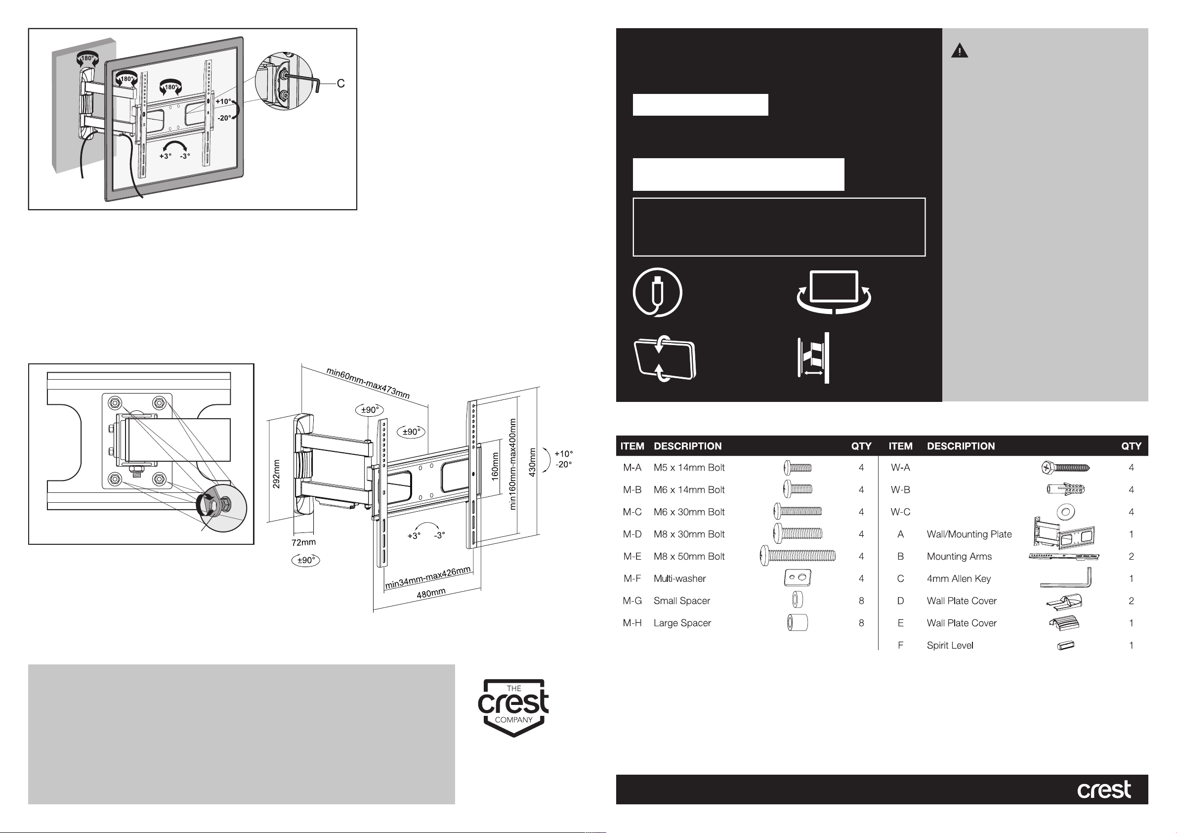
Hardware Kit Contents
Tools Required
DRYWALL INSTALLATION (TIMBER SUPPORTS):
• Adjustable spanner/socket set
• Philips head screwdriver
• Power drill
• High speed 4.5mm drill bit
• Stud nder
• Spirit level and pencil
MASONRY INSTALLATION:
• Adjustable spanner/socket set
• Philips head screwdriver
• Power drill with hammer function
• 10mm Masonry drill bit
• Spirit level and pencil
• Hammer
BRBFMM
HIDDEN
CABLE
-90° TO 90°
PAN
-20° TO 10°
TILT
UP TO 473mm
EXTEND
6
Step 5: Level Adjustment
1. In some instances a slight adjustment might be required to level the TV.
2. Using a second person to help, extend the bracket out as far as it will go as shown in gure 5 and have the second person hold
the TV.
3. Loosen the tension of the 4 bolts directly behind the mounting plate (as shown in gure 6) enough so you can carefully
adjust the left and right level of the TV.
4. Once the correct position has been reached tighten the bolts back up again to lock the levels position. It is important not
to over tighten the bolts.
7
Not included
FULL MOTION Articulated
32"-75"
TV WALL MOUNT
MEDIUM
400 x 400 MAX
VESA COMPATIBILITY
100x200,200x200,300x300,Ł
400x200,400x400
50kg MAX
TV WEIGHT
The maximum supported
weight is up to 50kg
6.3 x 55mm Lag Bolt
10 x 6 x 50mm Anchor
6 x 16 x 1.5mm Washer
Step 2: Attach Mounting Arms to TV
1. Using a second person for assistance, lay your TV face down on something soft so as not to scratch the TV screen.
Check the back of your TV to nd the appropriate mounting pattern.
2. Sort through the provided bolts (M-A to M-E) until you nd the correct size that easily ts into the back of your TV and ts
snugly (the bolt must turn at least 3 full turns, do not tighten). If you feel resistance stop immediately and select a smaller bolt.
Once you have selected the correct bolt size, use the multi-sized washer (M-F). If no bolts t you will need to go to your
local hardware supplier to nd the correct bolt and washer sizes.
3. Gently put your mounting arms (B) on the back of the TV so that the mounting holes are showing through the holes of the
mounting arms.
If the back of your TV is curved or recessed you will also need to use a spacer (M-G or M-H) depending upon the amount of
space you are trying to clear. If using a spacer you will also need to use longer screws. Remember that the bolt needs to turn
at least 3 full turns.
Step 1: Attach Wall Plate to Wall
A. INSTALLING IN DRYWALL (TIMBER SUPPORTS)
WARNING: The Crest Company holds no responsibility for incorrectly installed TV Wall Mounts.
1. Locate the centre of the timber studs using a stud nder.
(NOTE: You must use the centre of the stud to avoid cracking or splitting the timber during installation).
2. Mark a minimum of 3 xing holes over stud centres using the wall plate as a guide. Ensure plate is level.
3. Pre-drill holes to a minimum depth of 55mm using a high speed 4.5mm drill bit. If installing in hardwood, larger diameter
and deeper holes may be required.
4. Attach the wall plate using the lag bolts (W-A) through the washers (W-C). Do not over tighten.
5. Attach wall plate covers (D & E).
B. INSTALLING IN MASONRY
WARNING: Ensure you have a minimum of 35mm of actual concrete/brick thickness in the hole for the anchors. Do not drill into mortar joints.
Installer must verify that the supporting surface will safely support the combined weight of the TV Wall Mount and TV.
The Crest Company holds no responsibility for incorrectly installed TV Wall Mounts.
1. Mark a minimum of 3 xing holes over stud centres using the wall plate as a guide. Ensure plate is level.
2. Pre-drill holes to a minimum depth of 60mm using 10mm masonry drill bit. Clean out holes.
3. Fully insert concrete anchors (W-B). Tap in with hammer if required.
4. Attach wall plate by inserting the lag bolts (W-A) through the washers (W-C) into each concrete anchor (W-B). Do not over tighten.
5. Attach wall plate covers (D & E).
4. Using the correct mounting bolt size and length, insert these through the corresponding hole on the multi-sized washer (M-
F) to attach mounting arms to the rear of the TV. To avoid damaging TV, do not over tighten bolts.
The Crest Company is not responsible for any damage caused by screwing the bolt too far into the back of the TV.
1a 2
1b 2
3
4 5
Step 3: Hook Arms over Wall Plate
1. Using a second person for assistance, carefully lift the TV and hook arms over the top of the wall plate.
2. Slowly lower the bottom of the TV until the bottom of the mounting arm locks into the bottom of the wall plate.
3. Once your TV is in place tighten the screws at the bottom of the mounting arms. This will help ensure that your TV does
not fall o your wall plate during use.
4. Use allen key (C) to tighten mechanism as required.
5. To remove the TV from the wall plate, loosen the screws at the bottom of the mounting arms which will release the
mounting arms. Pull the bottom of the TV slightly towards you and then lift the TV from the wall plate.
Check your TV Wall Mount is secure and safe to use at regular intervals (at least every three months).
Step 4: Tilt Adjustment
1. Using a second person to help, extend the bracket out as far as it will go as shown in gure 6.
2. Loosen the tension of the bolts at the tilting mechanism using the provided Allen Key (C) enough so you can carefully
adjust the tilt angle of your TV to the desired angle.
3. Once the correct position has been reached tighten the bolts back up again to lock the angle is position. It is important not
to over tighten the bolts.

Other Crest Audio TV Mount manuals

Crest Audio CBTVFSSA User manual

Crest Audio

Crest Audio CBTVFSSA User manual

Crest Audio MFP64FM User manual

Crest Audio

Crest Audio MFP64FM User manual

Crest Audio MFP44FM User manual

Crest Audio

Crest Audio MFP44FM User manual

Crest Audio MFP44F User manual

Crest Audio

Crest Audio MFP44F User manual

Crest Audio BFP1FM User manual

Crest Audio

Crest Audio BFP1FM User manual

Crest Audio BFP2FM User manual

Crest Audio

Crest Audio BFP2FM User manual

Crest Audio CBMCFM User manual

Crest Audio

Crest Audio CBMCFM User manual

Crest Audio BRBFMC User manual

Crest Audio

Crest Audio BRBFMC User manual

Crest Audio MFP44T User manual

Crest Audio

Crest Audio MFP44T User manual

Popular TV Mount manuals by other brands

Speaka Professional 2377756 General safety instructions

Speaka Professional

Speaka Professional 2377756 General safety instructions

One Forall ULTRA SLIM WM6010 Quick installation guide

One Forall

One Forall ULTRA SLIM WM6010 Quick installation guide

InFocus LP340 installation instructions

InFocus

InFocus LP340 installation instructions

Monoprice 10906 user manual

Monoprice

Monoprice 10906 user manual

Barkan CM310 manual

Barkan

Barkan CM310 manual

OMCR VDI3366 Use and maintenance manual

OMCR

OMCR VDI3366 Use and maintenance manual

Sony SU-PW2 instructions

Sony

Sony SU-PW2 instructions

New Star Neomounts FL40-450BL14 instruction manual

New Star

New Star Neomounts FL40-450BL14 instruction manual

Sony PFM-42B1 Dimensional drawing

Sony

Sony PFM-42B1 Dimensional drawing

peerless-AV ACC450 Installation and assembly

peerless-AV

peerless-AV ACC450 Installation and assembly

New Star Computer Products NS-SHELF100 instruction manual

New Star Computer Products

New Star Computer Products NS-SHELF100 instruction manual

König Electronic TVS-MOT11C manual

König Electronic

König Electronic TVS-MOT11C manual

Kimex 091-2031 manual

Kimex

Kimex 091-2031 manual

peerless-AV tru-vue TRWV110/BK installation instructions

peerless-AV

peerless-AV tru-vue TRWV110/BK installation instructions

Bauhn AWBS-0818-W instruction manual

Bauhn

Bauhn AWBS-0818-W instruction manual

peerless-AV ACCXT101 Installation and assembly

peerless-AV

peerless-AV ACCXT101 Installation and assembly

Nextlevel Acoustics UM1-A user manual

Nextlevel Acoustics

Nextlevel Acoustics UM1-A user manual

Viozon OL-3L installation instructions

Viozon

Viozon OL-3L installation instructions

manuals.online logo
manuals.online logoBrands
  • About & Mission
  • Contact us
  • Privacy Policy
  • Terms and Conditions

Copyright 2025 Manuals.Online. All Rights Reserved.