SAFETY FIRST
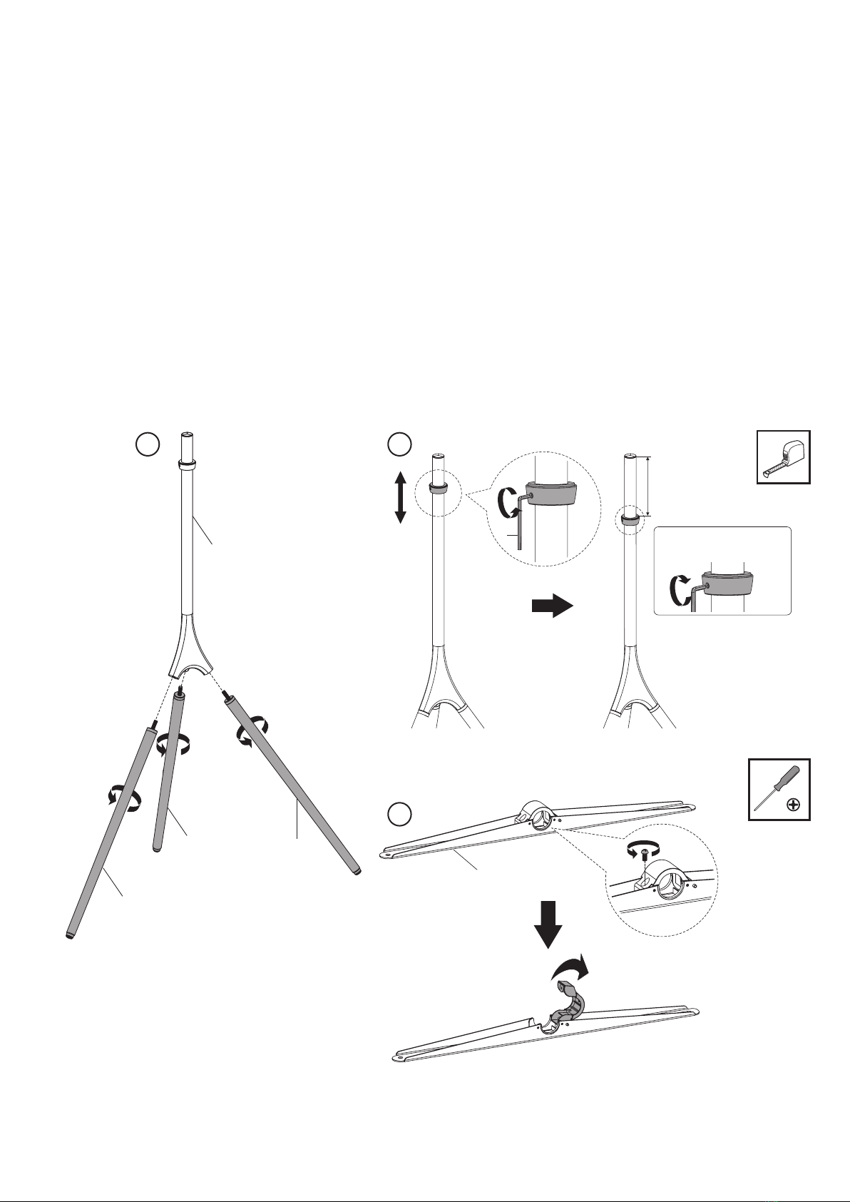
1. Installation of this TV Mount Floor Stand will be easier with
two people.
2. Some images in this guide may vary slightly from the actual
components supplied.
3. Ensure this instruction manual is completely read and
understood before attempting installation.
4. Please note that this product bears dierent weight load on
glossy (such as wood) and normal oors (such as concrete).
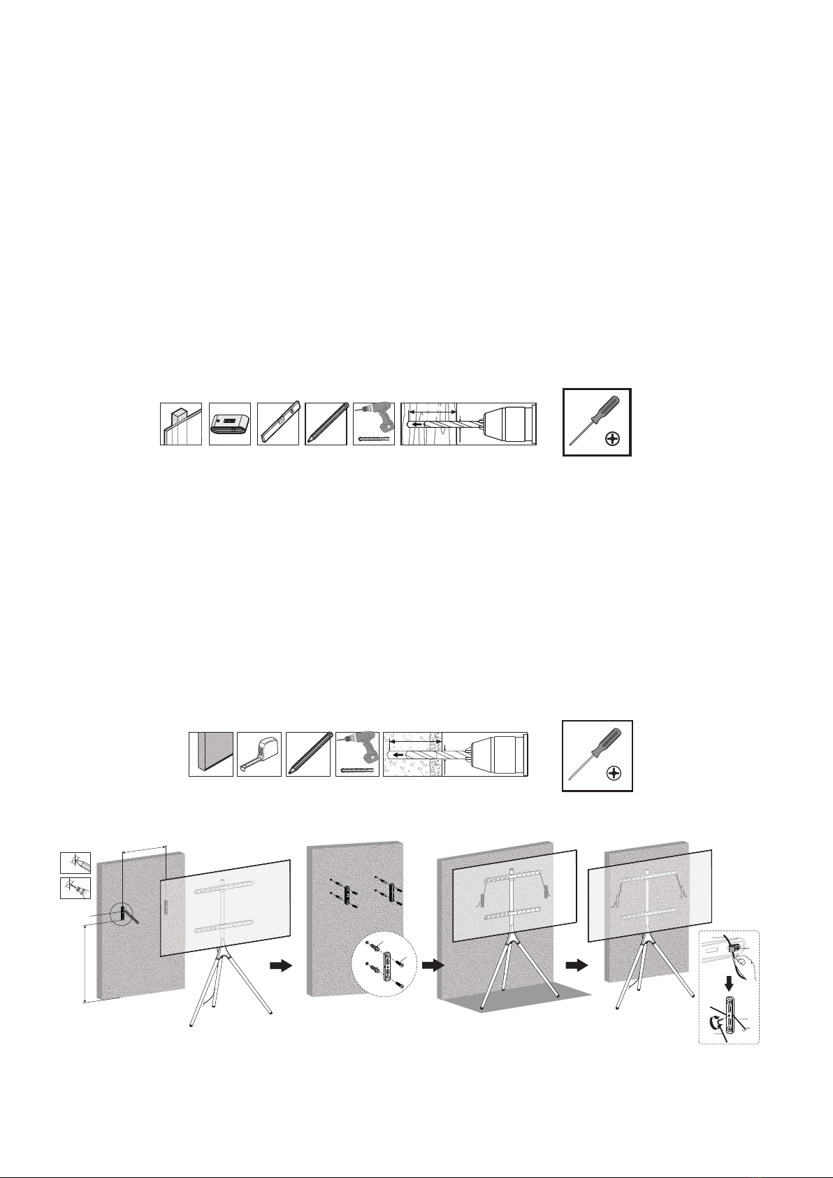
5. This product includes an anti-tip kit that must be used in
conjunction with the product and will prevent the product
from falling or tipping over. Keep anti-tip wire out of reach
of children.
6. Use appropriate tools and safety equipment and ensure
adequate ventilation during installation.
7. If uncertain about any aspect of installation, contact The
Crest Company or an installation professional.
8. Please retain these instructions for future reference.
CBTVFSSA
TV Mount
Universal Stand
Fits 45”-65” TVs
Flat and curved TV screens
45-65”
Supports Max 32kg
This TV Wall Mount supports TVs
weighing up to 32kg
32kg
600mmx400mm (WxH)
Max Pattern Size
Compatible mounting sizes:
200x200, 300x200, 300x300,
400x200, 400x300, 400x400,
600x400
600x400mm
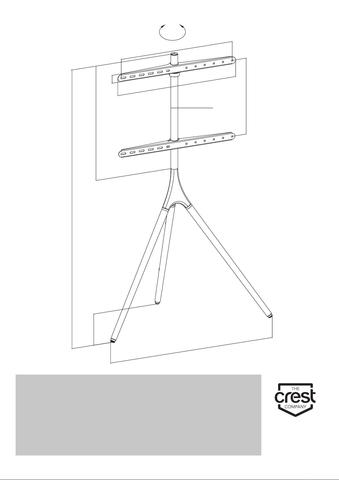
Full Motion
This TV Mount Floor Stand allows you
to swivel your screen 180° on either
side and provides cable management
solutions for a clutter-free zone.
Hardware Kit Contents
ITEM DESCRIPTION QTY ITEM DESCRIPTION QTY
A Front Tripod Leg 2 H Wall Mount 2
B Back Tripod Leg 1 I Cable Management Clip 2
C Bottom Bracket 1 J Small Screw 2
D Top Bracket 1 K 2mm Allen Key 1
E Stand 1 L 4mm Allen Key 1
F Anti-tip wire 1 M Large Screw 4
G Cable Management Clip 2 N Concrete Anchor 4
ITEM DESCRIPTION QTY ITEM DESCRIPTION QTY
M-A M5 x 14mm Bolt 4 M-E M8 x 50mm Bolt 4
M-B M6 x 14mm Bolt 4 M-F Multi-washer 4
M-C M6 x 30mm Bolt 4 M-G Small Spacer 8
M-D M8 x 30mm Bolt 4 M-H Large Spacer 8