manuals.online logo
Brands
  1. Home
  2. •
  3. Brands
  4. •
  5. Crestron
  6. •
  7. Cables And Connectors
  8. •
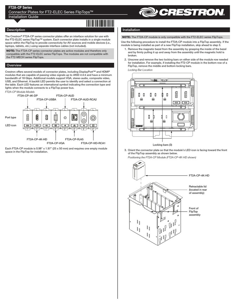
  9. Crestron Connect It TT-100 Series User manual

Crestron Connect It TT-100 Series User manual

DO GUIDE
TT-100 Series
Crestron Connect It™ Cable Caddy
DO Install the Device
The TT-100 Series is designed for installation into a conference table.
The required thickness of the table is 1/2 inch (13 mm) to 1-1/4 inches
(32 mm).
NOTE: The TT-100 Series includes the TT-100, TT-101, TT-110, and TT-111.
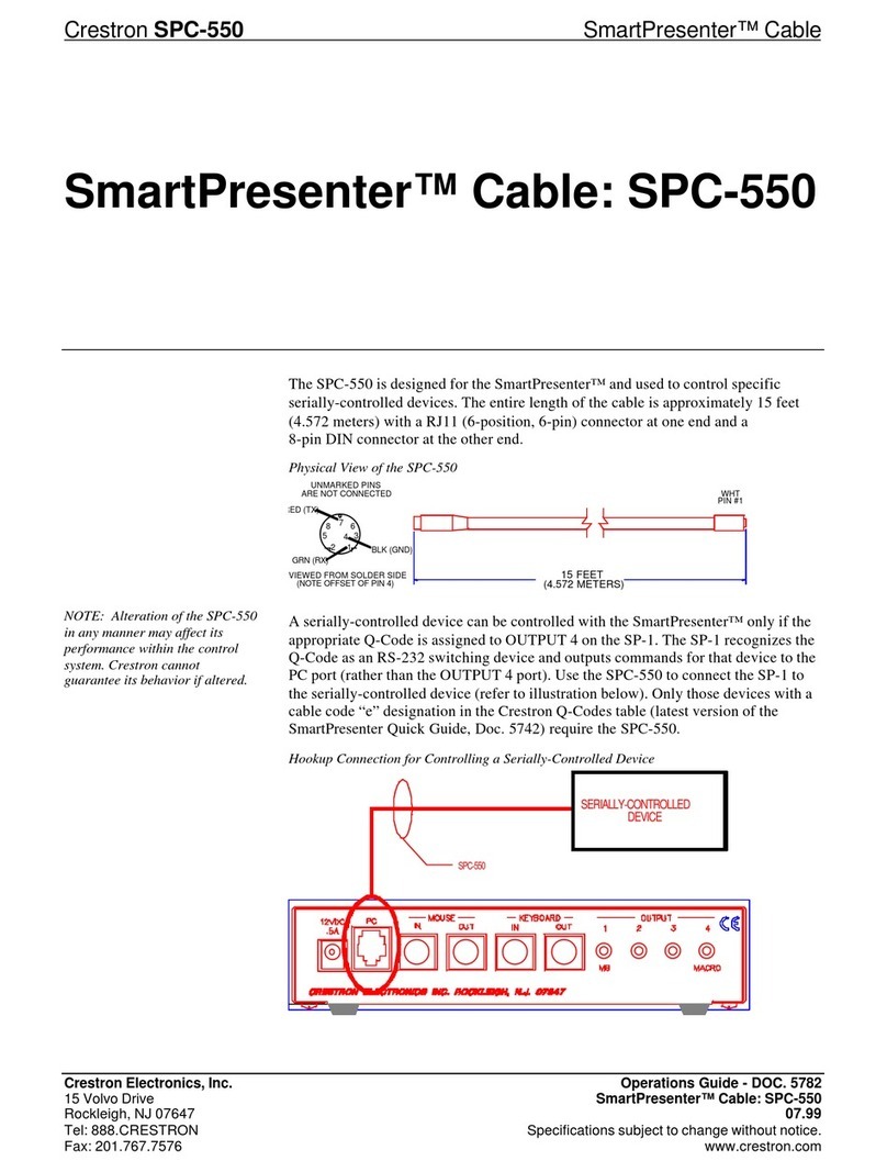
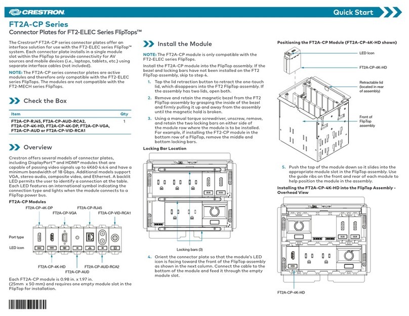
The TT-101 consists of the TT-100 plus HDMI®, VGA, audio, and Ethernet
cables. The TT-111 consists of the TT-110 plus HDMI, VGA, audio, and
Ethernet cables. The TT-100, which provides a power outlet, is shown for
illustrative purposes throughout the remainder of this guide.
To install a TT device, do the following:
1. Properly protect the surface of the table.
2. Using a 4-inch (102 mm) hole saw (not included), drill a hole in the
appropriate location in the table.
3. With the TT device positioned so that the Crestron®logo faces the
user of the device, insert the body of the device into the hole.
4. Twist the included locking ring onto the body of the TT device, leaving
a 1/8-inch (4 mm) gap between the locking ring and the bottom
surface of the table.
5. Using the included Allen wrench, tighten the three setscrews (included
with the locking ring) to secure the locking ring to the bottom surface
of the table.
6. Route the desired cables from the bottom of the TT device through
the cable opening. Up to four cables can be routed: one HDMI cable,
one VGA cable, one audio cable, and one Ethernet cable (all cables
supplied with the TT-101 and TT-111).
7. Insert the cables into the appropriate holes in the included cable plate.
8. Seat the cable plate in the cable opening, and then attach the plate
using the four supplied Phillips pan head screws.
DO Connect the Device
Connect the device as required for the application.
NET/USB Port Connection
NET and USB ports are located on the bottom of a TT device.
Use either the NET port or the USB port of a TT device to communicate
with a compatible DigitalMedia™ device:
• The NET port requires a Cresnet®control cable (not included) to
connect to a Crestron control system.
NOTE: When the NET port of the TT device connects to a control
system, the TT device receives power via the NET port.
• The USB port, which is a USB Type mini-AB port, requires the
included A to mini-B cable or B to mini-A cable to connect to the USB
port of a compatible DigitalMedia device.
NOTE: For proper USB functionality, the appropriate USB cable must
be connected to the TT device before the device is powered on.
The USB cable to be used depends on the USB type (Type A or
Type B) of the DigitalMedia device:
– When an A to mini-B cable connects the USB port of a
DigitalMedia device to the USB port of a TT device, the TT device
receives power via the USB port. Compatible DigitalMedia
devices that connect to a TT device using an A to mini-B cable
include the DMPS3-4K-150-C, DM-MD8X1-4K-C, HD-MD8X1-4K,
and DM-TX-401-C. The DigitalMedia devices have USB Type A
host ports, which supply USB power.
– When a B to mini-A cable connects the USB port of a
DigitalMedia device to the USB port of a TT device, the TT device
receives power via a connection to a Cresnet network or power
supply. A compatible DigitalMedia device that connects to a
TT device using a B to mini-A cable is the DM-TX-201-C.
The DM-TX-201-C has a USB Type B device port, which does
not supply USB power.
HDMI, VGA, Audio, and Ethernet Cable Connections
Connect HDMI, VGA, audio, and Ethernet cables as required for the
application:
• Connect one end of the HDMI/VGA/audio cable to the appropriate
output port of an audio/video source (for example, a laptop) and the
other end of the cable to the corresponding input port of a compatible
DigitalMedia device.
• Connect one end of the CAT5e Ethernet cable to a local network
device and the other end of the cable to the building network.
DO Check the Box
QUANTITY PRODUCT COLOR PART NUMBER
1 Cable, USB 2.0, A - Mini B, 6' 6" (2 m) Black 2025146
1 Cable, USB 2.0, B - Mini A, 6' 6" (2 m) Black 2038104
1 Connector, 4-Pin 2003576
1 Tool, 3/32" Allen Wrench 2036829
TT-100-B-T, TT-101-B-T, TT-110-B-T, and TT-111-B-T Only
1Cable Plate Black 2036696
1Locking Ring Black 4519116
4 Screw, 6-32 x 1/4", Pan Head, Phillips Black 2007215
TT-100-GRY-T, TT-101-GRY-T, TT-110-GRY-T, and TT-111-GRY-T Only
1Cable Plate Gray 2036697
1Locking Ring Gray 4519209
4 Screw, 6-32 x 1/4", Pan Head, Phillips 2007213
TT-101-B-T, TT-111-B-T, TT-101-GRY-T, and TT-111-GRY-T Only
1 Cable, Audio, Stereo, 1/8" Mini, 6' (1.83 m) 2037179
1 Cable, Ethernet, CAT5e, 7' (2.13 m) 2030114
1 Cable, HDMI, 6' (1.83 m) 2037173
1 Cable, VGA, 6' (1.83 m) 2037178
Not Included: 4-Inch (102 mm) Hole Saw; Phillips Screwdriver; and HDMI, VGA, Audio, and Ethernet Cables (Model Dependent)
24: Power, 24 Vdc (Red)
Y: Data (White)
Z: Data (Blue)
G:
Ground (Black)
NET
24 Y Z G
— —
NET
Port
USB
Port
Cable
Opening
TT-100 TT-110
Table
(User Side)
Setscrews
(3)
Table
(Bottom View)
HDMI
Audio/
Ethernet
Audio/
Ethernet
VGA
Phillips Pan Head
Screws (4)
Cable
Connections
(Up to 4)
Table
Locking Ring
1/8 in
(4 mm)
DO GUIDE DOC. 7833A (2045092) 10.15
Specications subject to change without notice.
Power Pass-Through Outlet Connection
(TT-100 and TT-101 Only)
Connect the grounded ac power pass-through outlet and the power cord
(not shown) as required. The maximum load is 10 A @ 125 V, 50/60 Hz.
DO Observe the Status Indicators
TT devices provide soft-touch capacitive Crestron Connect It™ buttons
with multicolored status indicators.
As of the date of manufacture, the TT-110 and TT-111 have been tested and found to comply with specications for CE marking.
The TT-100 Series is Listed to applicable UL Standards and requirements by Underwriters Laboratories Inc.
Federal Communications Commission (FCC) Compliance Statement
This device complies with part 15 of the FCC Rules. Operation is subject to the following two conditions:
(1) This device may not cause harmful interference, and (2) this device must accept any interference received, including interference that may cause undesired operation.
CAUTION:Changes or modications not expressly approved by the manufacturer responsible for compliance could void the user’s authority to operate the equipment.
NOTE: This equipment has been tested and found to comply with the limits for a Class B digital device, pursuant to part 15 of the FCC Rules. These limits are designed to provide reasonable protection
against harmful interference in a residential installation. This equipment generates, uses and can radiate radio frequency energy and, if not installed and used in accordance with the instructions, may
cause harmful interference to radio communications. However, there is no guarantee that interference will not occur in a particular installation.
If this equipment does cause harmful interference to radio or television reception, which can be determined by turning the equipment off and on, the user is encouraged to try to correct the interference
by one or more of the following measures:
• Reorient or relocate the receiving antenna.
• Increase the separation between the equipment and receiver.
• Connect the equipment into an outlet on a circuit different from that to which the receiver is connected.
• Consult the dealer or an experienced radio/TV technician for help.
Industry Canada (IC) Compliance Statement
CAN ICES-3(B)/NMB-3(B)
The specic patents that cover Crestron products are listed at http://www.crestron.com/legal/patents. The product warranty can be found at www.crestron.com/warranty.
Certain Crestron products contain open source software. For specic information, please visit www.crestron.com/opensource.
Crestron, the Crestron logo, Cresnet, Crestron Connect It, and DigitalMedia are either trademarks or registered trademarks of Crestron Electronics, Inc. in the United States and/or other countries. HDMI and the HDMI Logo are either trademarks or registered trademarks of HDMI Licensing LLC in
the United States and/or other countries. Other trademarks, registered trademarks, and trade names may be used in this document to refer to either the entities claiming the marks and names or their products. Crestron disclaims any proprietary interest in the marks and names of others. Crestron
is not responsible for errors in typography or photography.
This document was written by the Technical Publications department at Crestron.
©2015 Crestron Electronics, Inc.
DO Learn More
Visit the website for additional information and the latest rmware updates. To learn more about this product, use a QR reader application on
your mobile device to scan the QR image.
Crestron Electronics
15 Volvo Drive, Rockleigh, NJ 07647
888.CRESTRON | www.crestron.com
COLOR DESCRIPTION
Blue Video source is not connected.
Blinking Green Video is detected. The display is turning on.
Solid Green Video appears on the display.
Slowly Pulsating Green Video is detected; however, video does not
appear on the display.
Five Red Blinks No video is detected. The Connect It button is
touched. After ve red blinks, the color reverts to
blue.
Power
Pass-Through
Outlet
Crestron Connect It Buttons

This manual suits for next models

8

Other Crestron Cables And Connectors manuals

Crestron SmartPresenter SPC-124 User manual

Crestron

Crestron SmartPresenter SPC-124 User manual

Crestron FT2A-CP Series User manual

Crestron

Crestron FT2A-CP Series User manual

Crestron ZUMLINK-CONV-CN User manual

Crestron

Crestron ZUMLINK-CONV-CN User manual

Crestron TPSBLOCK-10 User manual

Crestron

Crestron TPSBLOCK-10 User manual

Crestron FlipTop CBLR2 Series Dimensional drawing

Crestron

Crestron FlipTop CBLR2 Series Dimensional drawing

Crestron UC-B-ACCY User manual

Crestron

Crestron UC-B-ACCY User manual

Crestron FT2-700-ELEC Series User manual

Crestron

Crestron FT2-700-ELEC Series User manual

Crestron CBL-USB-RS232KM-6 User manual

Crestron

Crestron CBL-USB-RS232KM-6 User manual

Crestron QM-FTCMK User manual

Crestron

Crestron QM-FTCMK User manual

Crestron FT2A-CP-USBA User manual

Crestron

Crestron FT2A-CP-USBA User manual

Crestron DigitalMedia Connectors DM-CONN-20 Owner's manual

Crestron

Crestron DigitalMedia Connectors DM-CONN-20 Owner's manual

Crestron TPMC-CBL-T User manual

Crestron

Crestron TPMC-CBL-T User manual

Crestron CBL-MULTI-HD-6 User manual

Crestron

Crestron CBL-MULTI-HD-6 User manual

Crestron SR9600 Configuration guide

Crestron

Crestron SR9600 Configuration guide

Crestron TPS-CBL-S User manual

Crestron

Crestron TPS-CBL-S User manual

Crestron HZA-KEY1 User manual

Crestron

Crestron HZA-KEY1 User manual

Crestron ST-CBL Operating and installation instructions

Crestron

Crestron ST-CBL Operating and installation instructions

Crestron DM-8G-CONN-100 User manual

Crestron

Crestron DM-8G-CONN-100 User manual

Crestron TPS-CBL User manual

Crestron

Crestron TPS-CBL User manual

Crestron SmarTouch ST-112 User manual

Crestron

Crestron SmarTouch ST-112 User manual

Crestron ST-SPL User manual

Crestron

Crestron ST-SPL User manual

Crestron Four-Way Amplified Splitter SRD-SPL-4 User manual

Crestron

Crestron Four-Way Amplified Splitter SRD-SPL-4 User manual

Crestron SmartPresenter SPC-121 User manual

Crestron

Crestron SmartPresenter SPC-121 User manual

Crestron FlipTop CBLR2 Series User manual

Crestron

Crestron FlipTop CBLR2 Series User manual

Popular Cables And Connectors manuals by other brands

Viessmann 4560 Operation manual

Viessmann

Viessmann 4560 Operation manual

SeaLevel VERSA COMM+4/EX user manual

SeaLevel

SeaLevel VERSA COMM+4/EX user manual

CommScope SYSTIMAX VisiPatch CPC5562 instruction sheet

CommScope

CommScope SYSTIMAX VisiPatch CPC5562 instruction sheet

PureTools PT-SP-HD14DA user manual

PureTools

PureTools PT-SP-HD14DA user manual

Rean RCAC3M-X-000 Assembly instruction

Rean

Rean RCAC3M-X-000 Assembly instruction

Siemens 3VA957-0JB23 Series operating instructions

Siemens

Siemens 3VA957-0JB23 Series operating instructions

AVI AVISP4K116 user manual

AVI

AVI AVISP4K116 user manual

Eaton COOPER POWER SERIES Installation instruction

Eaton

Eaton COOPER POWER SERIES Installation instruction

Philips SWV2205 Specifications

Philips

Philips SWV2205 Specifications

Philips SWV2514W Specifications

Philips

Philips SWV2514W Specifications

SOURIAU UTS MPO Series Assembly instructions

SOURIAU

SOURIAU UTS MPO Series Assembly instructions

Motorola RLN4853 manual

Motorola

Motorola RLN4853 manual

Philips SDW5206GN Specifications

Philips

Philips SDW5206GN Specifications

TAPKO MECip-Sec Product description

TAPKO

TAPKO MECip-Sec Product description

SIIG USB-to-PS/2 Adapter Quick installation guide

SIIG

SIIG USB-to-PS/2 Adapter Quick installation guide

Atlas Copco RTX-30 Quick setup guide

Atlas Copco

Atlas Copco RTX-30 Quick setup guide

Audiovox AH731R manual

Audiovox

Audiovox AH731R manual

Gefen EXT-HDMI1.3-142 user manual

Gefen

Gefen EXT-HDMI1.3-142 user manual

manuals.online logo
manuals.online logoBrands
  • About & Mission
  • Contact us
  • Privacy Policy
  • Terms and Conditions

Copyright 2025 Manuals.Online. All Rights Reserved.