Norac UC4.5 User manual

H
A
RDI Economy
HPZ and HAZ (18-30m) DAH09
Installation Manual
HD11

Printed in Canada
Copyright 2012 by NORAC Systems International Inc.
Reorder P/N: UC4.5-BC-HD11-INST Rev B (HARDI Economy HPZ and HAZ (18-30m) DAH09)
NOTICE: NORAC Systems International Inc. reserves the right to improve products and their specifications without notice and
without the requirement to update products sold previously. Every effort has been made to ensure the accuracy of the information
contained in this manual. The technical information in this manual was reviewed at the time of approval for publication.

Contents
1Introduction................................................................................................................ 1
2General UC4.5 System Layout................................................................................. 2
3Kit Parts ...................................................................................................................... 3
4Ultrasonic Sensor Installation .................................................................................. 5
5Roll Sensor Installation............................................................................................ 10
6Electrical Installation ............................................................................................... 12
7Software Setup......................................................................................................... 15
8Cable Drawings ........................................................................................................ 16

1
1Introduction
Congratulations on your purchase of the NORAC UC4.5 Spray Height Control System. This
system is manufactured with top quality components and is engineered using the latest
technology to provide operating reliability unmatched for years to come.
When properly used the system can provide protection from sprayer boom damage, improve
sprayer efficiency, and ensure chemicals are applied correctly.
Please take the time to read this manual completely before attempting to install the system. A
thorough understanding of this manual will ensure that you receive the maximum benefit from
the system.
Your input can help make us better! If you find issues or have suggestions regarding the parts
list or the installation procedure, please don’t hesitate to contact us.
Every effort has been made to ensure the accuracy of the information contained in
this manual. All parts supplied are selected to specially fit the sprayer to facilitate
a complete installation. However, NORAC cannot guarantee all parts fit as
intended due to the variations of the sprayer by the manufacturer.
Please read this manual in its entirety before attempting installation.
2
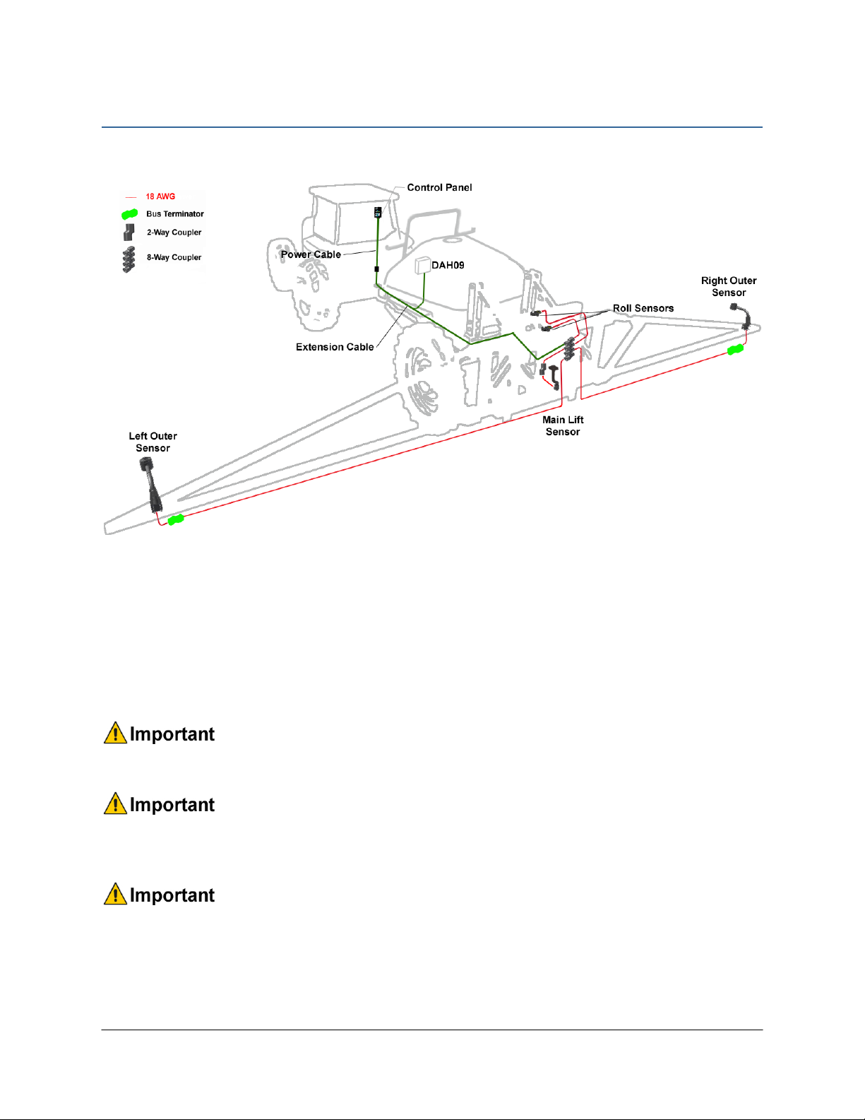
2General UC4.5 System Layout
Figure 1 illustrates the general layout of the UC4.5 system components:
Figure 1: General UC4.5 System Layout
Do not use high speed power tools/drills when installing hardware.
The use of dielectric grease is not recommended on any NORAC electrical
connections.
To ensure all stainless steel hardware does not gall or seize apply a light coating of
the supplied Permatex Anti-seize grease to all threaded parts upon installation.
Permatex Anti-seize lubricant is preferred, but other similar anti-seize products
may be used.
3
3Kit Parts
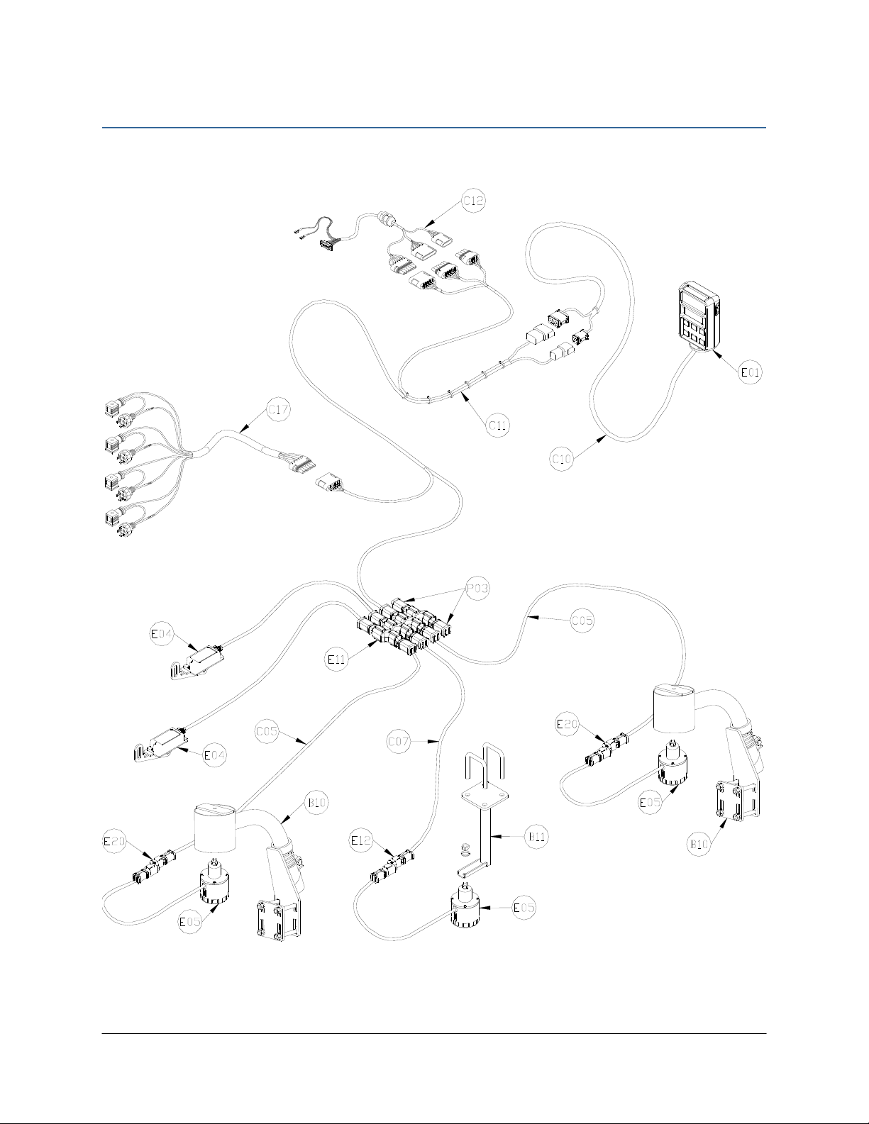
3.1 Kit Overview
Figure 2: HD11 System Parts

4
3.2 List of Parts
Item Part Number Name Quantity
B06 105728 RAM-233 RAIL MOUNT ADAPTER KIT FOR RAM-202 BASE 1
B10 44728 MOUNTING BRACKET COMPLETE UC4 BREAKAWAY EXTENDED 2
B11 44695-15 MOUNTING BRACKET UC4 SENSOR HARDI COMMANDER ML 1
B14 100610 BOLT HEX 3/8X1 STAINLESS STEEL 4
B15 100947 WASHER LOCK SPRING SS 3/8 IN 4
C05 43210-20 CABLE UC5 NETWORK 18 AWG 20M 2
C07 43220-01 CABLE UC5 NETWORK 14 AWG 1M 1
C10 44650-52 CABLE UC4.5 POWER HARDI 1
C11 44651-51 CABLE UC4.5 EXTENSION VALVE HARDI 1
C12 44658-78 CABLE INTERFACE HARDI DAH09 1
C17 44658-107 CABLE UC4.5 INTERFACE TWIN/FORCE DEMO 1
E01 45100 UC4.5 BOOM CONTROL PANEL 1
E04 43741 UC5 ROLL SENSOR VER. 2 2
E05 43750 UC5 ULTRASONIC SENSOR 3
E11 43765 UC5 NETWORK COUPLER 8-WAY 1
E12 43764 UC5 NETWORK COUPLER 2-WAY 1
E20 43764T UC5 NETWORK COUPLER 2-WAY WITH TERMINATOR 2
M01
UC4.5-BC-MANUAL-
OPERATOR
OPERATOR MANUAL UC4.5 SPRAY HEIGHT CONTROL 1
M02 UC4.5-BC-HD11-INST MANUAL INSTALLATION UC4.5 HARDI ECONOMY HPZ AND HAZ (18-30M) 1
M10 102084 TOOL PIN REMOVAL G.P. WITH NORAC LOGO 1
P03 105882 UC5 NETWORK 6 PIN PLUG 2
5
4Ultrasonic Sensor Installation
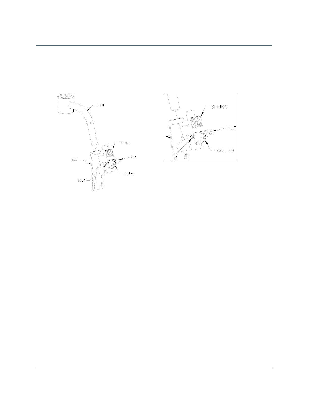
4.1 Bracket Assembly
Assemble the breakaway sensor bracket as illustrated in Figure 3, following the instructions
below.
Figure 3: Breakaway Bracket Assembly
1. Compress the spring and insert it together with the collar into the base.
2. Slide the tube through the assembled part.
3. Using the bolt and nut, tighten the collar to the tube with the sensor tube centered.
4. Apply a small amount of grease to the rotating surfaces of the bracket.

6
4.2 Ultrasonic Sensor Serial Number Arrangement
When installing the sensors, start with the smallest serial number on the left-hand side, and
proceed to the largest serial number on the right hand side. Each sensor has a serial number
stamped on the sensor housing.
Apply a light coating of the supplied Permatex Anti-seize grease to all threaded
parts upon installation.
Figure 4: Sensor Serial Number Arrangement

7
4.3 Ultrasonic Sensor Mounting Guidelines
The following guidelines will ensure optimal sensor performance and prevent sensor
measurement error. These rules should be followed for both the wing sensors and the main
lift (middle) sensor.
1. In its lowest position, the sensor must be 9 inches (23 cm) or more from the ground (A).
2. The centerline of the acoustic cone should be approximately vertical at normal operating
heights (A).
3. The bottom of the sensor must be at least 9 inches in front of the spray nozzles and boom
structure (B). (This does not apply for the main lift sensor)
4. The bottom of the sensor must be at least 9 inches above the spray nozzles (C).
5. Ensure there are no other obstructions with a 12 inch (23 cm) diameter circle projected
directly below the sensor (D).
6. The sensor bracket should be oriented forward (ahead of the boom).
7. Mount the NORAC ultrasonic sensor into the sensor bracket and run the sensor cable
through the sensor tube.
A problem can arise if a sensor is not mounted correctly. It is possible for the
sensor to read off of the boom instead of the ground. This may only become
apparent once the control system is switched from soil to crop mode.
Also be careful that the sensor bracket does not collide with any other part of the
boom when the boom is folded to transport position. If possible, mount the sensor
brackets while the booms are folded to ensure they will not cause interference.
Figure 5: Sensor Mounting Guidelines
Figure 6: Sensor Reading Off Boom
8
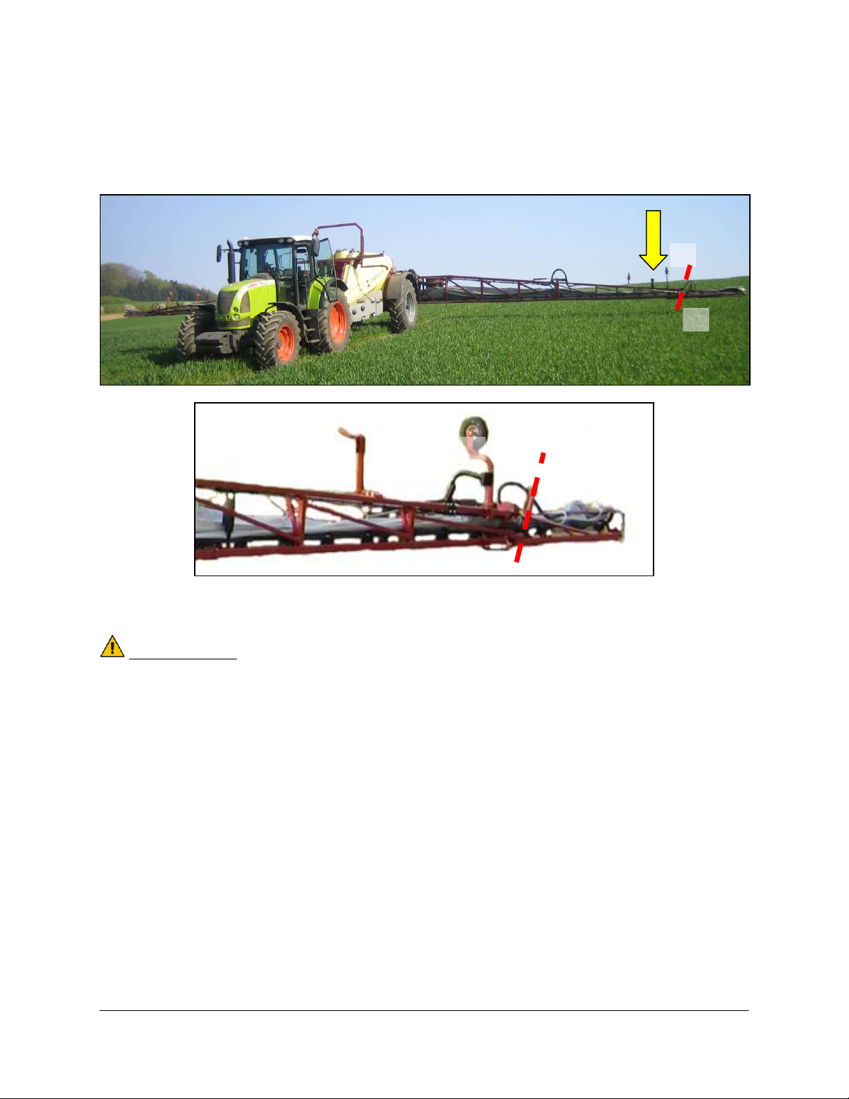
4.4 Wing Bracket Mounting
Below is the suggested mounting location for the wing sensor brackets. Mounting location is
just inside of the boom break-away section (A).
Figure 7: Suggested Bracket Mounting Location (viewed from front)
IMPORTANT:
Avoid mounting the bracket too close to the touch-down wheel (B).
(B)
(A)
(B)
(A)
9
4.5 Main Lift Sensor Installation
1. Mount the main lift bracket (B11) as illustrated in Figure 8. Ensure sensor cable is routed
properly and securely fastened.
2. Mount the Ultrasonic sensor to the bracket. Ensure the sensor has a clear view of the
ground. Ensure sensor cable is securely fastened with cable-ties.
Figure 8: Main Lift Sensor Mounted
10
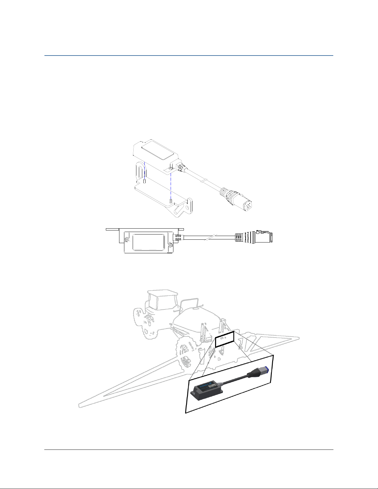
5Roll Sensor Installation
5.1 Bracket Assembly
1. Securely mount the roll sensors to the included roll sensor brackets using the #6 machine
screws. Tighten screws to 10 in-lbs (1.1 Nm).
2. The orientation of the mounted roll sensor to the roll sensor bracket will depend on the
bracket mounting. The roll sensor CANbus connector must be pointing towards the right
side of the sprayer (when looking from the rear of the sprayer).
Figure 9: Mounting Roll Sensor to Bracket
Figure 10: Roll Sensor Orientation - Connector Facing Right Wing

11
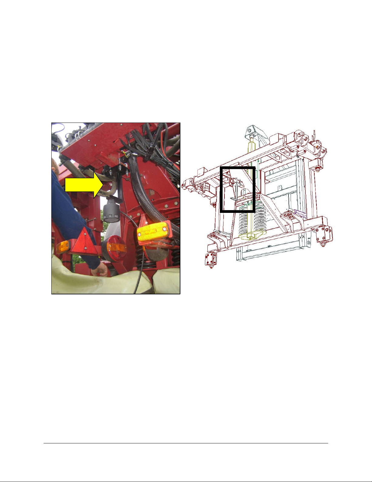
5.2 Roll Sensor Mounting
Ensure the 6 pin connector is pointing towards the right hand wing (when looking from the
rear of the sprayer). Fasten with cable ties.
1. Install one roll sensor (E04) onto the non-rotating part of the boom.
2. Install the second roll sensor (E04) onto the rotating part of the boom.
Figure 11: Roll Sensor Mounting (viewed from rear of sprayer)
E04
E03

12
6Electrical Installation
Ensure the UC4.5 Control Panel is OFF for the remainder of the installation
(Bottom of switch pressed IN). Use caution when handling the 12 V power line
of the sprayer wiring.
1. Install the UC4.5 Control Panel (E01) in the cab of the sprayer using the included mount
(B06). Mount the panel where it will be clearly visible and within easy reach of the
operator.
Figure 12: Cable Overview
2. Connect the UC4.5 power cable (C10) to the UC4.5 Control Panel in the cab. Ensure that
both plugs (P16 and P4) are connected to the panel.
3. Route the P12/P6 of C10 to the exterior of the cab.
4. Connect P12/P6 to R12/R6 of the extension cable (C11). Connect at the hitch. This
connection will provide the hitch disconnect.
5. Run cable C11 from the hitch to the rear of the sprayer.
6. Connect T4, T6 and S6 of cable C11 to S4, S6 and T6 of cable C12 respectively.
7. Run the DB15 connector and the wires with the spade connectors of C12 to the DAH09
PCB by passing it through a hole in the enclosure. Seal the hole using the weather-proof
strain relief fitting.

13
8. Connect the DB15 connector of cable C12 to the DAH09 DB15 connector.
9. Connect the red wire with spade connector on C12 to the Switched 12VCC on the
DAH09 board (Figure 13).
10. Connect the black wire with spade connector on C12 to the GND on the DAH09 board
(Figure 13).
Figure 13: DAH09 PCB for AutoHeight
a) Configure the system for Autoslant by setting the DIP switches on DAH09 board. Set
DIP switches 2,3,4,6 and 8 to ON. Set DIP switch1, 5 and 7 to OFF. (Figure 14)
Figure 14: Suggested Default Setting for DIP Switches 2-8 for AUTOSLANT
11. Close the electronics enclosure. Gather up any excess cable (C11 & C12) and neatly cable-
tie to the machine.
Note that on some sprayers the slant valve wiring varies from machine to
machine.
If the left-hand tip lifts when the left button is pressed, and the right-hand button lifts
the right hand tip (Figure 15), the wiring as described above is correct.
DB15
DIP switches
12 VDC and GND

14
Figure 15: Default Slant Direction Wiring
However, if the boom does the opposite of what is described above, it is necessary
to swap the E and F wires in the S6 connector of 44658-78 (C12).
12. Connect the 6-pin tower (T6) on the interface cable (C17) to the mating 6-pin shroud (S6)
on C11. Route the free end of C17 to the existing valve block.
13. Insert the tees (DF1-DM1 -> DF4-DM4) of C17 between the matching valve connections
(Left Up, Left Down, Right Up, Right Down).
14. Fasten the 8-way coupler to the boom with cable ties. Connect P6 on C11 to the 8-way
coupler.
15. Connect both roll sensors to the 8-way coupler.
16. Connect the main lift sensor to the 8-way coupler using cable C07 and a 2-way coupler
(E12). Cable C07 and item E12 may not be needed if the 8-way coupler is mounted close
enough to the main lift sensor.
17. Connect two cables (C05) to the 8-way coupler and route along the booms to the wing
sensors. Follow existing cables and hoses to be sure the cable will not be pinched or
stretched.
18. At the sensor brackets, attach a 2-way coupler with terminator (E20) to the sprayer boom.
The 2-way coupler with terminator is the white two way coupler. Plug the sensor and the
CANbus cable into the 2-way coupler.
19. Insert the 6-pin plugs (P03) into the unused connectors on E11.
IMPORTANT:
Provide enough slack in all cables to account for the movement of the main
section, parallel lift, and FOLDING boom movement.

15
7Software Setup
1. Start up the sprayer and test the sprayer’s functionality. The control panel does not need
to be powered on for the original boom function switches to operate. Unfold the booms
and raise/lower each boom and the main section.
Confirm that the cabling and hoses are agreeable to the entire range of motion.
2. If any functions do not work, review this manual to check for proper installation.
3. Turn on the power for the UC4.5 Control Panel using the switch on the side of its chassis.
4. The procedure for the installation of the UC4.5 Spray Height Control system is now
complete. Begin the AUTOMATIC SYSTEM SETUP procedure as described in the UC4.5
Spray Height Control Operator’s Manual (M01).
16
8Cable Drawings
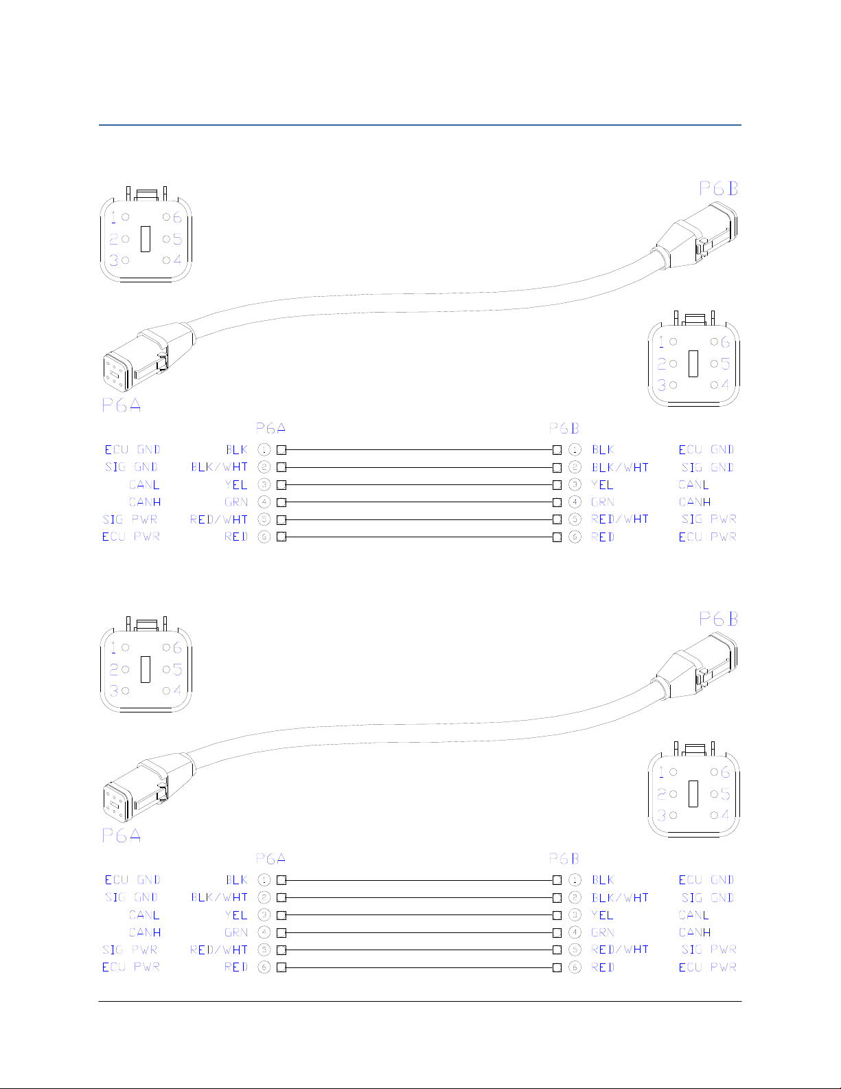
8.1 ITEM C05: 43210-20 - CABLE UC5 NETWORK 18 AWG - 20M
8.2 ITEM C07: 43220-01 - CABLE UC5 NETWORK 14 AWG - 1M
17
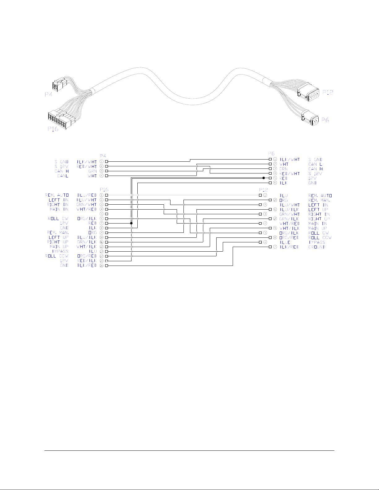
8.3 ITEM C10: 44650-52 - CABLE UC4.5 POWER HARDI
Other manuals for UC4.5
31
Table of contents
Other Norac Paint Sprayer manuals

Norac
Norac UC5 Topcon X30 User manual

Norac
Norac UC4.5 User manual

Norac
Norac UC5 Topcon X30 User manual

Norac
Norac Rogator 1286C User manual

Norac
Norac UC 4.5 Hagie STS10 User manual

Norac
Norac UC4.5 User manual

Norac
Norac UC4.5 User manual

Norac
Norac UC4.5 User manual

Norac
Norac UC4.5 User manual

Norac
Norac UC4.5 User manual

Norac
Norac UC4.5 User manual

Norac
Norac UC5 Topcon X30 User manual

Norac
Norac UC4.5 User manual

Norac
Norac UC5 Topcon X30 User manual

Norac
Norac UC5 Topcon X30 User manual

Norac
Norac UC4.5 User manual

Norac
Norac UC5 Topcon X30 User manual

Norac
Norac UC5 Topcon X30 User manual

Norac
Norac UC5 Topcon X30 User manual

Norac
Norac UC4+ User manual


