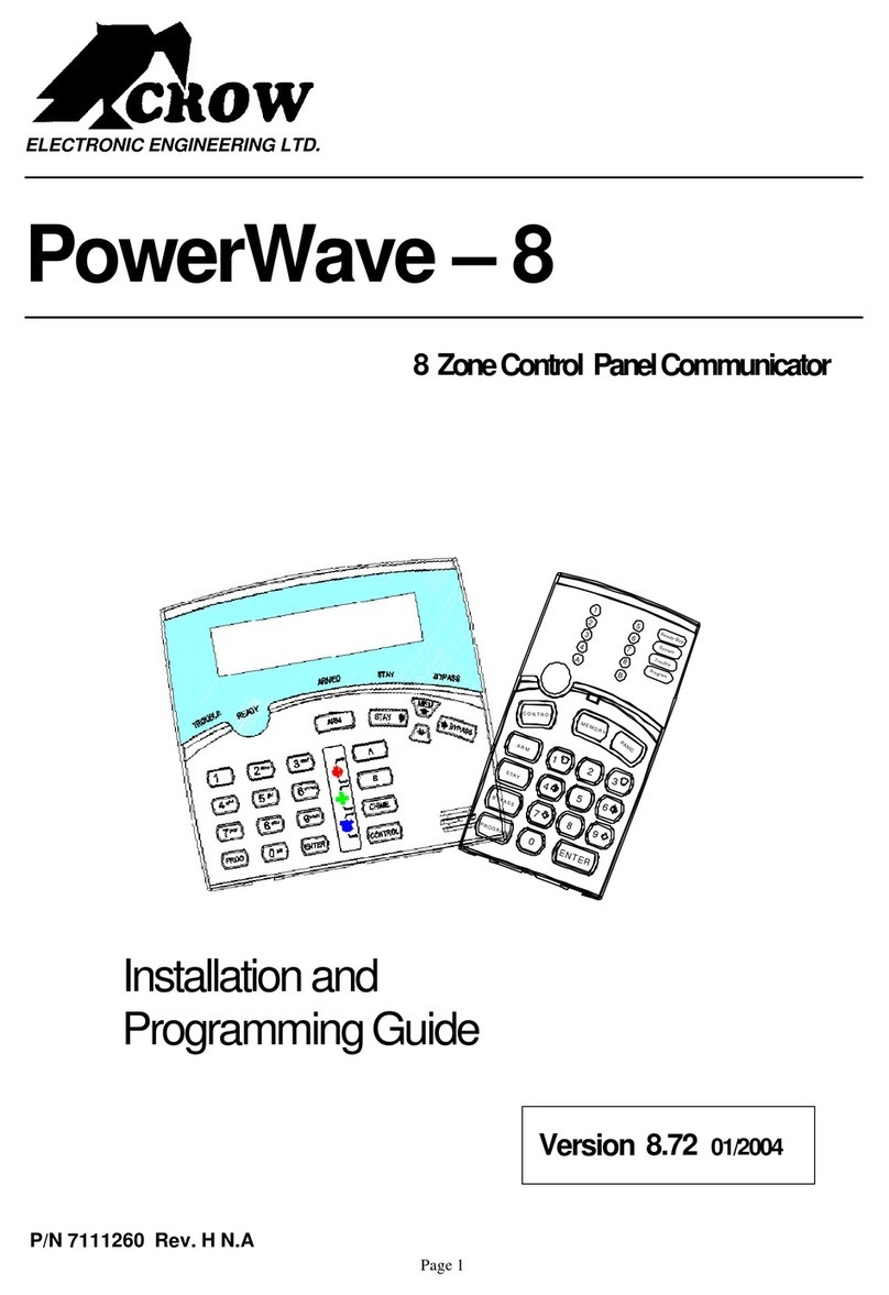
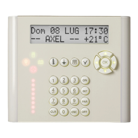
Crow PowerWave 8 User manual

P/N 7101261 Rev.C N.A10 December 2003
ELECTRON
IC ENGINEERINGLTD
.
PowerWave-8
&
PowerWave 8-‘LITE’
8zoneControlpanel Communicator
Users’Operating and
ProgrammingGuide
Version 8.71 /8.72
(CoversVer:8.64 and above)

2
Notes:

3
Contents
Introduction..………………………………………………….5
MeettheCrowAlarmControlSystem……………………...5
TypicalAlarmSystemConfiguration………………………5
KeypadDescription………………………………………….6
FunctionKeys….……………………………………………6
Alphanumeric Keys…………………………………………6
AudibleSignals……………………………………………..7
Indicators……………………………………………………7
SummaryofFunctions………………………………………7
Operation……………………………………………………...9
HowtoArmtheSystembeforeExit………………………...9
HowtoArmtheSystemwhenStayingHome………………10
HowtoArmPartitions………………………………………10
HowtoBypass Zones……………………………………….11
HowtouseChime (If enablebyInstaller)………………….11
EmergencyAlerts……………………………………………11
GenerateThreator Duress…………………………………..12
HowtoReadSystemMessages……………………………..12
HowtoReadTroubleMessages…………………………….13
HowtoDisplayEvents fromMemory………………………13
HowtoControlOutputs and Devices……………………….15
HowtoGetintotoUser Program/ClientMode……………..15
HowtoChangeor AddCodes………………………………15
HowtoChangeMaster Code………………………………..16
HowtoAddor ChangeUser Code………………………….16
HowtoDeleteUser Code…………………………………...16

4
HowtoAddor ChangeTelephoneNumbers…………………16
HowtosetTimeandDate…………………………………….16
Howtooperatetheaccess controloutput…………………….17
HowtostartWalk test Mode………………………………….17
HowRemotecommandcontrolworks……………………...18
Warranty..……………………………………………………………..20

5
Introduction
Meet the CrowAlarmControl System
Thankyou forchoosingtoprotectyourpremiseswitha PowerWave-8 ofCrowElectronic
EngineeringLtd.
PowerWaveofCrow ElectronicEngineeringLtd.isahighlyadvanced,multifunction alarm
control system,designed toflawlesslymanageyoursecuritysystemat homeor at
business,protects you against burglaryand supportstheoperation ofelectronic devices.
The PW8hasmanyincredibleprogramoptionsandadditional accessoriesthat can
enhancethestandard featuresofthepanelfrom“Wireless control” toVoicePrompted
Telephonecontrol”. Pleaseaskyour installer tofind outmoreabout thesepowerful
features.
You can phoneyour hometocheckorchangethestatusofanyoutput usingthekeyson
yourphone. Armordisarmthewholehouseorjustonearea, all with yourown voice
confirmingyour selections.
Thecontrollerwill support a8LED keypad or themoresophisticated LCD (liquid Crystal
Display)keypad.
It alsohasacomprehensivealarmeventmemorythat storesall ofthecontrolleractivity
withthe timeanddate.
Typical Alarm System Configuration
Theprotected premisescanbedivided up to8zones,asdefined bytheinstallation
scheme. Theprotected area can begrouped into2separatepartitions(A and B).The
systemcan begrouped forUser‘s conveniencetoseparate,inabusiness environment,the
offices fromthewarehousearea, or in aprivateresidence, thedifferent roomsof thehome,
e.g. separate downstairs living area,detached garage, etc
Eachzonecan reactdifferentlytovariousevents,togenerateanalarmor activatea
device.
The systemcan bearmedintwo differentmodes:
1) Arm –theprotected areas areentirelyvacated
2) Stay –peopleandpetspopulate the protected areas.
The Userwho hasaccess to thekeypad'scontrol features,canchangethe settings.
Thesystemcan beaccessed viamultiplekeypads(eachlocated atadifferentsite). Up to
8keypadscan beintegrated intothesystem.Access levelsandUsers’access codesare
detailed below.

6
KeypadDescription
TheLED Keypad showsall theinformation required tooperatethesystem.TheUser
communicateswiththealarmsystemviathekeypad.TheKeypaddisplayscontinuous
information aboutthestatusofthealarmsystem,and enablestheUsertooperatethe
systemindifferentmodes, change settings and programUsers'access codes.
The keypadalsocollectsandrecordseventstobedisplayedafterwardonrequest,to
overview system activities,andtoanalyse systemperformancefordiagnostics.
Function Keys
Thesekeysareusedtoarmthe system,enter commandstoaltersystemsettings,or scroll
through the historyevents.
ARM, STAY, BYPASS, PROGRAM,CONTROL , MEMORY, PANIC , ENTER
1
2
3
4
A
5
6
7
8
B
Ready-Byp
System
Trouble
Program
7
4
123
56
98
0ENTER
PROGRAM
BYPASS
STAY
ARM
CONTROL
MEMORY
PANIC
Alphanumeric Keys
Thesekeysareusedtoenter codes,Initiate Emergencyorforprogramming.

7
Audible Signals
Thekeypad emitssignals(beeps)inresponsetoUseractivities.Thesesignalsarelisted
in Table. Table: List of Audible Signals
SoundSequence Description
Short beep OnceonlyA keyin thekeypad has beenpressed
3 short beepsOnceonlyOperationcarried out successfully
Long beepOnceonlyIllegal operation,or wrong keypressed
Slowbeeping Through the Exitor
Entrydelaytime Exitor entrydelaywarningwhen arming
the systemindicatesthat you must exitthe
protected area,
alsoEntrydelaywarning when entering
via theentryzone,to disarmthe system.
Indicators
Thereare 14 LEDs indicatorsshow the status ofthesystem.
Zoneand Statusindicators LEDs1-8
Partitions indicatorsLEDsA, B
ReadyBypindicator
Systemindicator, Troubleindicator
Program indicator .
Summaryof Functions
The system'smain functions arelisted in table
FunctionKeysDescription Notes
Full
or Partition
ArmCC OD E C
ENTER
Initiatesfullarm
Full Arm C
ARM
InitiatesfullarmOnlyif enabledby
installer
Disarm
duringexit C
ARM
Disarmsthe
systemduring
exitdelay
Onlywhenslow beeping
is emitted
Disarm CC OD E C
ENTER
Disarmsthe
system Stopping Alarms
ArmStay C
STAY
CC OD E Initiates partial
alarm whenthe
user is home
Onlyif enabledby
installer

8
C
ENTER
ArmStay C
STAY
Initiates partial
alarm whenthe
user is home
Disarm
Stay CC OD E C
ENTER
Disarmsthe
system
Disarm
Stay C
STAY
Disarmsthe
system
Bypass C
BYPASS
C
Zone#
C
ENTER
Bypasses a
zone(s) Repeats theprocedureto
un-bypass zones
Initiate
Panic C
PANIC
Activates panic
alert
Initiate
Panic C1+ 3Activates
emergencyalert Onlyif enabledby
installer
FunctionKeysDescription Notes
Initiate
Medical
C7+9Activates
emergencyalert Onlyif enabledby
installer
InitiateFire
Alarm C4+6Activates
emergencyalert Onlyif enabledby
installer
Memory CMEMORY Initiates display
of eventsfrom
memory.
<ENTER>
cancels memory
readout
Displays events,and
automaticallyscrollsto
the next event every2.5
sec.
(Use <MEMORY> keyto
scrollup manually)
Chime
Enable/dis
able CCONTROL CPROGRAM Enableor
disable chime
function
Onlyif enabledby
installer
Control C
CONTROL
CDevice#
C
ENTER
Activates or
deactivates
outputs and
devices
Press <Control> for2
seconds
Changeor
AddUsers'
code CPROGRAM CMCODE
C
ENTER
Activates
programmode to
addor change
Users' codes
Fordetailssee
page12
Note:Ifyou started an operation incorrectly,press <ENTER>toexitand
return totheprevious mode.

9
Operation
Howto Arm the System beforeExit
• Preparingthe System for Arming
Verifythat thegreen<ReadyByp>indicator islit.Thisindicatorislit onlywhen allzones
areclosed (alldoors,exitsandwindowsareclosed and motion intheprotected area is
restricted or bypassed) ,thesystemisreadytobearmed. Ifthegreen <ReadyByp>
indicator isnot illuminated, the zoneLED 1 to8 is litdisplays theopen zones.
Closeopenzones,or bypass them.Bypass anyzoneyoucannotclose,the<Ready
Byp>indicator flashes indicating bypassed zone(s) . Fordetailssee page9.
Note:Bypassed zones are not protected.
• Armingthe System
Beforeleaving premisesthesystemhastobearmed.
WhenthesystemisReady,indicatorislit, enter user code andthen <ENTER>toarm
the system.
Thereisaexit delayprior tothesystembeing armed.During thisdelaytime, aslow
beepingisheardtoindicatethat thesystem isnot armedyetand remindsyoutoleavethe
protected area.
The Aindicator lights upto indicate thatthe systemis armed.
(Theindicatorsmaygooutfewsecondsafter exitdelayexpired,depending on the
installer'ssetting).
Ifyou mustdisarmthe systemduring theexitdelay,press <ARM>.
• Quick Arm (When enabled bythe installer)
Whenthe systemisReady,press <ARM> toarmthesystem.
The Aindicator lights upto indicate thatthe systemis armed.
During exitdelaytime, aslowbeepingisheard toindicatethat thesystemisnotarmed yet
and reminds youto leavetheprotected area..
• Disarmingthe System
Enter User’scode andpress <ENTER>.The Aindicatorgoesoff toindicatethat the
systemis disarmed.
• StoppingAlarms
In caseofalarmcondition ,Enter User’scode andpress<ENTER>tostopalarmany
time.

10
Howto Arm the System when StayingHome
• Armingthe System in Stay Mode
Thistypeofarming isused when peoplearepresent within theprotected area. At night
time, when thefamilyisabouttoretire,perimeter zonesareprotected, but not theinterior
zones.Consequently, interior movements will be ignored bythe system.
Whenthe systemisReady,press<STAY> , enter user code, andthen <ENTER>.
The Aindicator flashestoindicate that the systemis armed in staymode .
• Quick Stay
Whenenabled bytheinstaller,press <STAY>toarmthe system.
During exitdelayyoucanleavethepremises.Ifyou wishtostayorthat noonewillenter
theprotected premises,youmaycancel theEntry/exitdelaybypressing the<ENTER>
key. The slow beeping stops andthe systemis immediatelyarmed.
The Aindicator flashestoindicate that the systemis armed in staymode .
(Theindicatorsmaygoout afewsecondsafterexit delayexpired,depending on the
installer'ssetting).
• Disarmingthe System
Enter user’s code andpress <ENTER>, or press <STAY>if enabledbyinstaller.
The Aindicator goes off toindicatethat the systemisdisarmed.
Howto Arm Partitions
Theprotected areacan begrouped intotwo separatepartitions(Aand B). Thesystem
can begrouped forUser ‘s conveniencetoseparate, in abusiness environment, theoffices
fromthewarehousearea, orinaprivateresidence, thedifferent roomsofthehome, e.g.,
living room, bedroom, etc.
To arm partitionAenter usercodefor partitionA
To arm partitionBenter usercodefor partitionB,
Note:toarming partition with code see page7 “How toarmthesystembeforeexit”
During exitdelayyou can leavepremises.At theendoftheproceduretheAindicator or
the B indicator lights upto indicate thatthepartition A and/orB is armed.
(Theindicators maygoout after a fewseconds, dependingon the installer'ssetting).
Todisarmpartition,see"Disarmingthe System".

11
Howto Bypass Zones
Bypass anyzonethat cannotbeclosed. You canbypass selected zonespriortoarming.
It is also used to temporarilyexcludea faultyzone fromservice, which requires repair.
Tobypass aselected zone, press <BYPASS>, theReadyBypindicator and program
indicator lightsup to indicate that the systemisin bypass mode.
Enter the zone number oneormorezones,thezoneLEDindicatorslightsuptoindicate
that thezoneisbypassed ,followingpress <ENTER>,theReadyBypLED flashesto
indicatezone(s) bypassed .
Toun-bypass,press <BYPASS>, enter zone number, and<ENTER>.
Note:Disarmingautomaticallyun-bypasses zones.
Howto use Chime(If enable by Installer)
AChime(Dayzone) isadetector that can bepartarmedwhileyouareat homebut
workingin another part ofthe building. It can be programmedtooperatea buzzer or lightto
letyou know youhaveavisitor.
Todisablethisfunction,press <CONTROL>,ProgramLEDandSystemLEDindicators
lights up,press the<PROGRAM> , Program LED flashesto indicatethat Chimeisdisabled
.
ToenableChimemodepress <CONTROL>and<PROGRAM>againProgramLED goes
off toindicate that Chime is enabled .
EmergencyAlerts
Thisspecial key’sfunction isbestprogrammed byyourinstaller tosuityourindividual
situation. Mostcommonlyit is used inapanic situation tosoundonlytheoutsidesiren and
perhapscallamonitoringstation.
• Howto initiatePanic
Press the<PANIC>or Press simultaneously<1>and<3> .
• Howto initiateMedical Alarm
Press simultaneously<7>and<9>.
• Howto initiate Fire Alarm
Press simultaneously<4> and <6>.

12
Generate Threat or Duress
Ifyou arecompelled todisarmthesystemunder threat, you mustenter theduress digit
beforetheuser’scodetoactivatetheautomaticdialer. Theduress digit shiftsup your
usual codebyonedigit. Ifyourcodeis345and 8isyourduress digit, than entering 8345
will modifyyour code. Themodified duress codewill disarmthesysteminanormal way,
butat thesametimewillactivatethedialersilentlytoreporta“duress event”without
arousing suspicion.(For details ask installer.)
Howto Read SystemMessages
Whenviewingthememoryevents at thekeypadbypressing the<MEMORY>,the first thing
that will alwaysbe displayedis the systemmessages.
Ifthesystemled turnsON butnoother ZoneLED’sareONat thesametime,thismeans
that therearenocurrentsystemalarms.IfazoneLED andLED’sareON then this
indicatessystemalarmsthat havenot yet cleared.TheLED’s1-8 arepre-defined asto
whatsystem alarmtheywilldisplay. These systemalarmindications areshown
in thetablebelow. Following thedisplayofcurrent systemalarmsthepanel willthen
sequencethrough the127historical memoryeventsstartingatthemostrecentevent. The
secondtableshowsthealarmeventsthatcan bedisplayedinmemorymodeandwhat
indicators areused to show them.
LED # 1 BatteryLowLED #5
Radio Pendant BatteryLow
LED #2Mains FailureLED #6
Supervised DetectorFailure
LED #3TelephoneLineFailureLED #7
ZoneInactivityTimeout
LED #4Radio Detector BatteryLow LED #8
DialerKiss-off Failure

13
Howto Read Trouble Messages
Anyfailureor abnormal eventsthat mayoccur areindicated bytroublemessages,and the
Troubleindicator is lit. Press <MEMORY>toread outmessagesand other events stored in
memory.
Howto DisplayEvents from Memory
Thesystemmemorystoresthelastevents.Press <MEMORY>todisplaylistofevents.
Following the displayofcurrentsystemalarmsthepanel willthensequencethrough
the 127 historical memoryeventsstartingat themost recentevent. Thesecond table
showsthealarmeventsthat canbedisplayed inmemorymodeand what indicatorsare
usedto show them.
Thesystemwill displaythelastevent andautomaticallyscroll tothenextoneevery2.5
seconds, and abeepis emitted. Usethearrow keys toscroll upmanually.
Wait until allmessages are displayed,orpress <ENTER>to cancel memoryreadout.
EVENTTYPE
DEVICE INDICATOR STATUS
ACTIVATION Zones1-8 LED's 1-8 On Steady
BYPASS Zones1-8 ReadyByp
LED's 1-8 On Steady
On Steady
DETECTORTAMPER
(SHORTCIRCUIT) Zones1-4 Trouble
LED's 1-4 Flashing On
Steady
DETECTORTAMPER
(OPEN CIRCUIT) Zones5-8 Trouble
LED's 5-8 Flashing On
Steady
CABINETTAMPER Cabinet or Satellite
Siren Trouble Flashing
LOW BATTERY ControllerBattery System
LED 1 On Steady
On Steady
MAINSFAILURE ControllerMains
Supply SYSTEM
LED 2 On Steady
On Steady
RADIO ZONELOWBATTERY
RadioPIR Zone1-8
LED's 1-8 Flashing

14
PENDANT LOWBATTERY RadioKeyUser1-8
Trouble
LED's 1-8 On Steady
Flashing
PANIC BUTTON(or
BUTTONS1&3 PRESSED
TOGETHER)
Keypad Panic System Flashing
FIRE ALARM(BUTTONS4&6
PRESSED TOGETHER) Keypad Fire System
AREA A Flashing
Flashing
MEDICAL ALARM(BUTTONS
7&9 PRESSEDTOGETHER)
Keypad Medical System
AREA B Flashing
Flashing
PENDANT PANIC RadioKey
User1-8 System
LED 1-8 Flashing
Flashing
ARMEDA Area A isArmed AREA A On Steady
ARMEDB Area B isArmed AREA B On Steady
STAYMODEA Area A STAYMode
ON AREA A Flashing
STAYMODEB Area B STAYMode
ON AREA B Flashing
DURESS ALARM Duress Alarm Trouble
AREA A& B
On Steady
Flashing
SUPERVISEDRADIO ALARM
Supervised Radio
Passive Infra-Red System
Trouble
LED’s 1-8
On Steady
Flashing
Flashing
ZONE INACTIVITY ALARM Zones1-8 ReadyByp
Trouble
LED’s 1-8
On Steady
On Steady
On Steady
TELEPHONE LINE FAILURE
Phone Line Failure Trouble
LED 3 On Steady
On Steady

15
Howto Control Outputs and Devices
Thekeypadenablescontrol ofexternal devices,suchasanair-conditioneror heater. To
activateor haltadevice, press <CONTROL>,ProgramandSystemLED’slightsup
steady,press the number of thedevice , up to8different devicescanbecontrolled via
thekeypad,then press <ENTER>toactivateordeactivatetheselected device. Tocheck
whatoutputsareON simplypress the<CONTROL>key,LED’scorrespondingtodevice
ON lightsup .Press <ENTER>to return tonormal mode.
Howto Get into to User Program/Client Mode
Thereare2levelsofprogrammode,CLIENT modeand INSTALLER mode. Normallythe
installer will giveyouaccess tothe CLIENT modesoyou can add, delete, or changethe
usercodes.Ifyou requestit yourinstaller can provideyouwith access totheINSTALLER
modeaswell. Toget intoCLIENT modeprovided thesystemis NOTarmed Press
<PROGRAM> enter Mastercode and <ENTER>.The Program indicatorlightsupto
indicate that the systemisin Userprogrammingmode.
Ifyou get asinglelong beep at thispoint and theProgramLED doesn’t turn on, itmeans
your code cannot access Program mode.
• Howto exitprogram mode
Toexitoutofprogrammodepress <PROGRAM> and <ENTER>.The Program indicator
goesoff toindicate that thesystemisnot in User programmingmode.
Howto Change or AddCodes
AboutMaster code and User code
Thefactorydefault mastercode(123) isintended asapreliminarycontrol ofthealarm
system.After PowerWaveisinstalledand putintoservice, thecodecan bechangedto
anycodeknown totheMaster user.TheMaster usercan defineupto9usercodes.To
limit access rights,theholder oftheMastercodecan asktheinstaller todefineseveral
Userprofiles.
Access rights are listed below:
- UsercodehasArea A and/or Bpermission
- Usercode can armand/ordisarmarman area
- Usercode can armand/ordisarmarman area in Staymode
- Usercode can change itscode
- Usercode can change user’scode
- Usercode can change dialler telephone numbers
- Usercode can alter the realtime clock

16
Howto Change MasterCode
Whileinclientmode,Press <PROGRAM>and 1tochangeMastercodepress <ENTER>,
thecodedigitwill beflashedbacktoyou.Usethenumerickeyboardtoenter yournew
Master code. Thecodecan holdanycombination of1 to 6 digits.It is recommended using
amulti-digitcode. .Press <ENTER>tosaveyournewcode,thenewcodewillbeflashed
toyou and 3short beepstoindicatecorrectentryor1long beep ifnotaccepted. Press
<PROG>and<ENTER>exit userCodeProgrammode.
Howto Add or Change User Code
Whileinclient mode, press <PROGRAM>andthe User number (2to 10)toadd or
changethecode,press <ENTER>.Ifthereisanexistingcodealready,it willbeflashed
back toyou.Usethenumerickeyboardtoenter thenew code.Thecodecan holdany
combination of 1to 6 digits.Enteringthenew codewill deletetheoldcode. Press
<ENTER> to save yournew code , the new codewill be flashed toyou and3 short beeps.
Repeattheprocedure for all users.
Press <PROG>and<ENTER> toexitLocal Program mode.
Howto Delete User Code
Whilein client mode, press <PROGRAM>and the User number (2to 10)youintend to
delete,press<ENTER>.Thecodewillbeflashedbacktoyou.Press <BYPASS>to
delete Usercode. Press <ENTER> to save the change.
Press <PROG>and<ENTER>exit programmode.
Howto set Time and Date
The alarmsystemhas an internal clockthat maybe used toautomaticallyArmor Disarm
thealarmor turn OutputsOn or off. Itis alsoused to identifywhen events occurred in
memoryviatheLCD keypad. Shouldyou need tochange the Time &Date itmustbe done
from CLIENT mode.
Tochange theTime & Date press
Press <PROGRAM> <403> <ENTER> <1-7> <ENTER>
Where1-7 =the current day(1=Sun, 2 =Monto 7= Sat)
Press <PROGRAM> <401> <ENTER><HHMM> <ENTER>
WhereHH =Hour in24Hour Format and MM= Minutes
Press <PROGRAM> <405> <ENTER><1-31><ENTER>
Where1-31 = the currentdate
Press <PROGRAM> <406> <ENTER><1-12><ENTER>
Where1-12 = the currentmonth
Press <PROGRAM> <407> <ENTER><YY> <ENTER>
WhereYY = currentyear, e.g. 02=2002

17
Howto Add or Change Telephone Numbers
Your panel will accept upto4phonenumberswith atotal of16 digits.Your panel canbe
programmed todial all or anyofthesedepending on theeventwhichhasoccurred.(The4
phone numbersareat programaddress 501 throughto504).
While in CLIENT mode, keyinthe following sequence<PROGRAM> <501><ENTER>
(Theaddress for telephonenumber1), Theexisting number willbe flashed out atthe
Keypadthen enter <NEWTELEPHONE#> <ENTER> The new numbers will be flashed
back to confirmacceptance.
At anytimeyoucan enter in theaddress for the telephonenumberjust toview the currently
programmed value then press the<PROGRAM> buttontomoveontoanother address.
Note:Address 501= PH #1, 502= PH#2 to 504= PH#4.
(Note:on the LED keypad “0”is indicatedby LED “A”and “9” by LED“B”)
Howto operate theaccess control output
Ifthealarmsystemhasbeen set up toallowcontrol ofan electric door lock,you can
activate the doorrelease function asfollows;
Press <CONTROL> or Press <CONTROL>enter CODE then<ENTER>
The Control LED will lights up while thelock is activeandturnoff as soon as power is
removedfromthelock.
The Access Control function can eitherbeasinglebutton operationorrestrictedto
requiringavalidUsercodeentry.Bothoptionsareshown above.Pleaseconsult your
installer astowhat option maybe programmed.
Howto start Walk test Mode
Whilein CLIENT modeaUserwith theproper authoritycan start walk-testmode. This
special modelatchesthealarmsignalsfromdetectorsatthekeypadinitiating thetestso
that onepersoncantriggereverydetectorconnectedtothealarmthenreturntothe
keypadtoverifyoperation. OnterminatingWalk-testmodethetestresultsareput intothe
memorybuffer sotheycan beviewed at alatertime.
Tostart Walk-testmodewhileinCLIENT mode press <PROGRAM><627> <ENTER>
The keypad buzzer will beep at1-second intervals
Next trigger everydetector connected to the panel thenreturn to thekeypad and all of the
zonesthat were triggered will bedisplayed at thekeypad.
ToterminateWalk-testmodepress<ENTER>
The keypad will stop beepingandautomaticallyexitCLIENT mode.

18
HowRemote Telephonecontrol works
Another powerful featureavailable fromyouralarmisTelephone Control. Thisfeatureis a
remote control facilitywhich allows validuserstoaccess the panel viaa standardtouch
tone telephoneandcheckor changethe Arm/Disarmstatus of eachoftheareas, operate
each oftheeight outputs or turnon an optionalMicrophone.
The TelephoneControl featureis onlyavailableon panelsfitted with a Voiceor DTMF
board. TheVoiceboardprovides voice promptsto guideyou through Telephone control
operations whereasthe DTMFboardprovides tones(oneLong Tonefor ON or three short
beepsfor OFF).
Please talktoyour installerto find out if all or anyoftheseoptions areavailableon your
alarm.
Toperformanyof the Telephone Control features you must first ringthephonenumber,
whichthepanel isconnected to.The panel maybe setup toanswer after a specific
number ofrings ofitmaybeset-up tousea faxdefeat option(ring once,hangup and call
back within30sec).Either way,when youring thephonenumber and thepanel answers
the call, the first thingyou willhear overthephoneis aburstof modemtone fortwo
seconds. Afterthis tone hasstopped you mustenter theaccess code,which is associated
withthe Telephonemenu option you wish toaccess. Remember, the code you enter will
determine whichmenuoptionyouaccess. If you miss thepause,the panel willrepeat the
modemtoneand then again pausefor5 secondslookingfor youraccess code. This
process will be repeated4 times beforehangingup ifnovalid code isreceived.When
enteringcodes or other information in Telephone Control the"#" keyacts as a "Clear"
button.
Whenyou haveentered the required 4-digit access code thepanel will replywith the status
messageassociated withthe Telephone Controlfunction youhaveaccessed. For
example, letssaywe havea codeof“2045” toallowArming &Disarming ofArea A. Once
the code “2045”hasbeenreceived the panelchecksthecurrent status ofArea A and
replies with the pre-programmed voicemessage relating to that status e.g. ifArea A is
Armed thenthe Armedmessagewillbe sent, ifDisarmed then the Disarmed messagewill
besent. If onlythe DTMFboard isfitted, thevoice messageissubstituted with alongbeep
ifArea A is Armed,and three shortbeepsifit isdisarmed.
Oncethe statusmessagehas informed you oftheactual state, youcan usethe "*" keyto
toggle theoption on & off orArmand Disarm,e.g. inour exampleabove, code “2045”
accessesArea "A" armingor disarming.
Assumingthe status messagewe received was"Area A alarmis Armed" Ifwepress the
"*" key,Area "A" willbe Disarmed and we would receivea statusmessage "AreaA alarmis
Disarmed" (orwhatever message is programmedbytheinstaller)
While you areon-linewith thepanel youcan movebetween menuoptionsbyentering the
codeoftheoption you want to control.Assuming therewas a codeof“4321” programmed
tocontrol outputs. After having used code“2045” to control the Arm/Disarmstatus ofArea
Awefirstpress the “#”buttonto reset allprevious entries. Then wecan enterthedigits
“43215” (that is “4321” as the code to control outputs and “5” toselectoutput #5). The
current status of output #5 willbegiven either bythevoicemessageor theappropriate
toneand then the statuscan be changed with the“*” button on the remotetelephone (Note;
Foroutput control you mustenter in the 4digit codee.g.4321 followed bytheoutput
number you wish to control, in thiscase5).

19
At anystage, if you enter inan incorrect codeyoucan press the“#” button ontheremote
telephone to clear all codeentriesandthenstart again.
Toturnon theoptional Microphone (onlyavailableifthe Voice Boardisfitted) you must
enter in theappropriate codefollowedbythe “*” button.Toturn theMicrophoneoff you
simplypress the “*” button again.
Toenda Telephone Control sessionsimplyhangs upthephone. The panelis monitoring
the lineat all times and15 seconds after thelast keypress it willautomaticallyhangupthe
line. This15-second timer is activeduringthewhole Telephone controlprocess soa
period of15 seconds without akeypress willcause the panel tohang-up.
HowLocal control works
Ifa Telephone controlcode foroutputsis programmed andtheoutput/s areallowedtobe
locallycontrolledfromthekeypad, then entering the 4 digitcodeat akeypad will blankthe
displayand thezoneLED’s willnow indicate theoutputstatus e.g. if output 1is on zone 1
LED willbeon.Bynowpressingthe “1” button at the panelkeypad, output 1canbe turned
off provided it is allowedtobelocallycontrolled. Toleavelocal Telephonecontrolmode
simplypress the<ENTER> button and the keypad will return tonormal operation.This
featureworks the samewaythat “DirectlyControllingan Output”works(see page14) only
it requiresacode toaccess the function.

20
Warranty
CROWLIMITED WARRANTY
(Crow)warrantsthisproduct to be free fromdefectsinmaterialsand
workmanshipunder normaluseand service for aperiod ofthree years
fromthe lastdayofthe week and year whosenumbersare printed on
the printedcircuit board inside hisproduct.
Crow’sobligation islimited to repairing or replacing thisproduct, at its
option, free ofcharge for materialsor labour, if itisproved to be
defectiveinmaterialsor workmanshipunder normal useand service.
Crow shall have no obligation under thisLimited Warranty or otherwise if
the product isaltered orimproperly repaired or serviced by anyone other
then Crow.
There are no warranties,expressed orimplied, ofmerchantability or
fitness for aparticular purposeor otherwise, which extend beyond the
description on the face hereof.In no caseshall Crowbe liable to anyone
for any consequentialor incidentaldamagesfor breach ofthisor any
other warranty, expressed or implied, or upon any other basisofliability
whatsoever, even ifthe loss or damage iscausedby Crow’sown
negligence or fault.
Crow doesnot represent that thisproduct cannot becompromised or
circumvented; that thisproduct will preventany personinjury or property
loss or damage by burglary, robbery, fire or otherwise; orthat this
product willinallcasesprovide adequate warning or protection.
Purchaser understandsthat aproperlyinstalled and maintained product
can onlyreduce the riskofburglary, robbery or othereventsoccurring
without providing an alarm, but it isnot insurance oraguarantee that
such will not occur orthat there willbe no personalinjury or property loss
or damage asaresult.Consequently, Crowshall haveno liabilityfor any
personalinjury,propertydamage or any otherloss based on claim that
thisproduct failed to giveany warning. However,ifCrowisheldliable,
whetherdirectlyor indirectly,for any lossor damage arising under this
limited warranty or otherwise, regardlessofcauseor origin, Crow’s
maximum liability shallnot inany case exceed thepurchase price
of this product, whichshallbe the complete and exclusive remedy
againstCrow.
This manual suits for next models
2
Table of contents
Other Crow Control Panel manuals

Crow
Crow Power Wave - 8 User manual

Crow
Crow PowerWave - 64 Operating instructions

Crow
Crow RUNNER 8/64 Operating instructions
Crow
Crow Serenity Series User manual
Crow
Crow Runner Series Operator's manual
Crow
Crow RUNNER-8 Operating instructions

Crow
Crow PowerWave-64 Installation guide

Crow
Crow Runner Series Operator's manual

Crow
Crow Power Wave - 'ST' User manual

Crow
Crow Runner Series User manual

