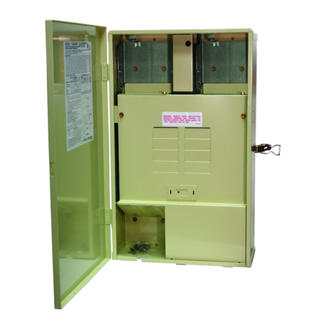
Crow Power Wave - 'ST' User manual

ELECTRONICENGINEERING LTD.
Power Wave-’ST’
&
Runner Series
WIRELESSAND WIRED CONTROL PANEL
User’sGuide
NOV-2005

RUNNER SERIES – User’sGuide

Crow LimitedWarranty
(Crow) warrants thisproduct to befree from defects in materials
andworkmanshipunder normaluse andservice for aperiodof
one year fromthe last dayof theweekandyear whose numbers
are printedon the printedcircuit boardinside his product.
Crow’s obligation islimitedto repairingor replacingthis product,
at its option, free of charge for materials or labor, if it is provedto
bedefectivein materials or workmanshipunder normal useand
service. Crow shall have no obligation under this LimitedWarranty
or otherwise if the product isalteredor improperlyrepairedor
servicedby anyone other then Crow.
There are no warranties, expressedor implied,of merchantability
or fitness for aparticular purpose or otherwise, which extend
beyondthe description on the face hereof. Inno case shallCrow
beliable to anyone for anyconsequential or incidental damages
for breach of this or anyother warranty,expressedor implied,or
upon anyother basis of liabilitywhatsoever, even ifthe loss or
damage is causedby Crow’s own negligence or fault.
Crow does not represent that thisproduct can not be
compromisedor circumvented;that thisproductwill prevent any
person injuryorpropertylossordamageby burglary,robbery,
fire or otherwise;orthat this product willin allcases provide
adequate warningorprotection. Purchaser understandsthat a
properlyinstalledandmaintainedproduct can onlyreduce the risk
of burglary,robberyor other events occurringwithout providing
an alarm, but itisnot insurance or a guarantee thatsuch will not
occur or thatthere will beno personal injuryor propertyloss or
damageas a result.Consequently,Crow shallhaveno liabilityfor
anypersonal injury,propertydamageoranyotherloss basedon
claim that thisproduct failedto giveanywarning.However, if
Crow is heldliable, whether directlyor indirectly,for anyloss or
damagearisingunder thislimitedwarrantyorotherwise,
regardless of cause or origin, Crow’s maximum liabilityshallnot in
anycase exceedthe purchase price of this product, which shall be
the complete andexclusive remedy against Crow.
© 2005. Allrights reserved.
Information in this document is subject to change without notice.
No part of this document maybe reproducedor transmittedin any
form or by anymeans, electronic or mechanical, without express
written permission of
.
P/N 7101585RevA Y.A August 2005


i
Contents
INTRODUCTION..................................................................1
THE CROW ALARM CONTROL SYSTEM ......................................1
TYPICAL ALARM SYSTEM CONFIGURATION .................................2
KEYPAD DESCRIPTION........................................................3
FUNCTION KEYS ................................................................4
ALPHANUMERIC KEYS..........................................................4
AUDIBLE SIGNALS..............................................................4
INDICATORS ....................................................................5
SUMMARYOF FUNCTIONS.....................................................5
OPERATING THE KEYPAD....................................................7
HOW TO ARMTHE SYSTEM BEFORE EXIT ..................................7
Preparing the System forArming................................7
Arming the System.....................................................7
Quick Arm (When enabled atinstallation)....................8
Disarming the System.................................................8
Stopping and Resetting Alarms...................................8
ARMINGTHE SYSTEM WHILE STAYING HOME .............................8
Arming the System inStayMode................................8
Disarming the System.................................................9
HOW TO ARM PARTITIONS ...................................................9
HOW TO BYPASS ZONES ....................................................10
USING CHIME (IF ENABLED AT INSTALLATION).........................11
EMERGENCY ALERTS .........................................................11
Howto initiate Panic.................................................11
Howto initiate Medical Alarm....................................11
Howto initiate Fire Alarm..........................................11
GENERATE THREATOR DURESS ...........................................12
HOW TO READ SYSTEM MESSAGES .......................................12
HOW TO READ TROUBLE MESSAGES ......................................13

RUNNER SERIES – User’sGuide
ii
HOW TO DISPLAY EVENTS FROM MEMORY ...............................13
HOW TO CONTROL OUTPUTSAND DEVICES ..............................15
ENTERINGTHE USER PROGRAM/CLIENT MODE ..........................15
HOW TO CHANGEOR ADD CODES .........................................16
About Master code and User code.............................16
Howto Change Master Code.....................................16
Howto Add or Change User Code.............................17
Howto Delete User Code..........................................17
ADDING/CHANGING TELEPHONE NUMBERS...............................18
HOW TOSET TIMEAND DATE ..............................................18
HOW TOOPERATETHEACCESSCONTROLOUTPUT.......................19
HOW TOSTART WALK TEST MODE ........................................19
HOW TOANSWERAN IN-COMING CALL ....................................20
USING THE REMOTE COMMAND CONTROL ................................20
USING LOCAL COMMAND CONTROL........................................23
LCD KEYPAD......................................................................25
ADJUSTING BACKLIGHTING AND BUZZER TONE ..........................25
LCD KEYPAD IN LOCAL EDIT MODE .......................................26
LCD KEYPAD LOCAL EDIT MODE MENU PROGRAMMING....28
Changing the Area SingleCharacter Identifier............30
Changing the Zone Names........................................30
Changing the Keypad Area Name..............................32
Changing the Keypad Name......................................32
Changing the User Names.........................................33
Changing the Output Names......................................33
Resetting Individual Text to Default orLast Saved
Setting.......................................................................33
Resetting All Text toDefault.......................................34
Copying Text toanother LCD Keypad........................34
Exiting LocalEditProgram Mode...............................34
CUSTOMIZATION CHART..................................................37

1
Introduction
TheCrow Alarm ControlSystem
Weare really pleased that you chose to protect your
premises and possibly even your lives with our
RUNNER SERIES from CrowElectronic Engineering
Ltd.
The RUNNERSERIES is a highly advanced,
multifunction alarm controlsystem,designed to
flawlessly manageyour securitysystem at homeor at
business,protects you againstburglary and supports
the operationof multiple electronicdevices.
The RUNNER SERIES has manyincredible program
options and additionalaccessories that can enhance the
standard features of the panelfrom simple “Home
Automation” to “Radio control” and Voice Prompted
Command control”.Please askyour installer to find out
more about these powerful features.
You can phone your home to check or changethe
status of any output using the keys on your phone. Arm
or disarm the whole house or just one area,allwith
your own voice confirming your selections.
Imagine turning on the spa before leaving work soit is
hot when you get inthe door.Theunder-floor heating
has just automatically switched on using the on board
timer and you have just opened the roller-door and
disarmedthe garage fromyour cell phoneso thewhite
ware repairman can work on your washer.
The controller supports a 16 LED keypad or the more
sophisticated LCD(liquid CrystalDisplay) keypad.
It also has a comprehensive alarm event memory that
logs all controller activity with a time and date stamp.

RUNNER SERIES – User’sGuide
2
TypicalAlarm System Configuration
The protected premises can be divided up into 16
zones,as defined bythe installation scheme.
The protected area can begrouped into two separate
partitions (A and B).
The system enables you in a business environment,to
conveniently group separately,the offices from the
warehouse area,or in aprivate residence,the different
rooms of the home.For example,living room,
bedroom,and maybe the basement and attic.
These groups or zones can reactspecifically to different
types of events and then generating an alarm or
activate a device.
The system can be armed intwo different modes:
Arm – the protected areas are entirelyvacated
Stay – people and pets populate the protected areas.
You have access to thekeypad's controlfeatures,and
can change the settings yourself.
The system can be accessed viamultiplekeypads (each
located at a different site).Up to eight keypads can be
integratedinto the system.Accesslevels and your
access codes are describedlater on inthisguide.

3
Keypad Description
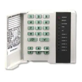
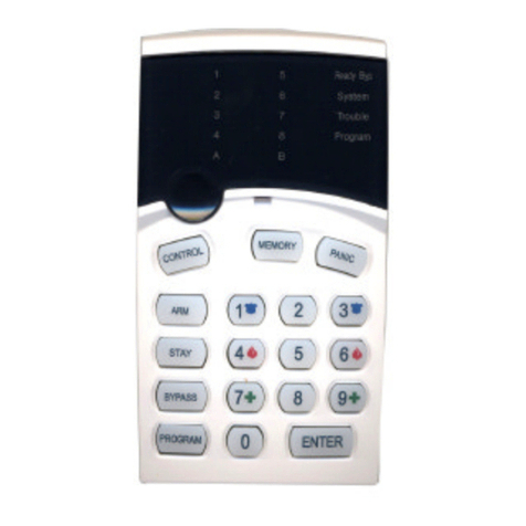
The LED Keypad shows allthe information requiredto
operate the system.The User communicates with the
alarm systemviathe keypad.The Keypad displays
continuous information about the status of the alarm
system,and enables the User to operate the systemin
different modes,change settings and programUsers'
access codes.
The keypad also collects and records events to be
displayed afterward on request,to overview system
activities,andto analyze system performance for
diagnostics.

RUNNER SERIES – User’sGuide
4
Function Keys
These keys are used to arm the system,enter
commands to alter system settings,or scrollthrough
the historyevents.
ARM,STAY, BYPASS,PROGRAM, CONTROL,
MEMORY, PANIC,ENTER
Alphanumeric Keys
These keys are used to enter codes,Initiate Emergency
or used for programming.
AudibleSignals
When the keypadis usedto activate or deactivatethe
different functions it emits different audible beeps.
Theirmeaning isdescribed in the tablebelow.
Table 1 Listof Audible Signals
SoundSequence Description
Short
beep
Once only Akeyinthe keypadhas been
pressed
3 short
beeps
Once only Operation carriedout
successfully
LongbeepOnce only Illegal operation, or wrongkey
pressed
Slow
beeping
Through the Exit or
Entrydelaytime
Exit or entrydelaywarningwhen
armingthe system indicates that
you must exit the protected
area,
also Entrydelaywarningwhen
enteringvia the entryzone, to
disarm the system.

5
Indicators
There are 30 LEDindicators to show the status of the
system.
qZone and Status indicatorsLEDs1-16
qPartitions indicatorsLEDsAor B
qArmedindicator,Memoryindicator,Bypass
indicator
qProgram indicator, Auxindicator, Mainsindicator
qTamperindicator, Batteryindicator, Line
indicator, Control indicator
Summary of Functions
The system's mainfunctions arelistedin table
Func. KeysDescriptionNotes
Full
or
Partition
Arm
CC OD E C
ENTER
Initiatesfullarm
Full Arm C
ARM
InitiatesfullarmOnlyif enabled
byinstaller
Disarm
during
exit
C
ARM
Disarmsthe
systemduring
exitdelay
Onlywhenslow
beeping is
emitted
Disarm CC OD E C
ENTER
Disarmsthe
system
Stopping Alarms
Func. KeysDescriptionNotes
ArmStay C
STAY
CC OD E
C
ENTER
Initiates partial
alarm whenthe
user is home
Onlyif enabled
byinstaller
ArmStay C
STAY
Initiates partial
alarm whenthe
user is home
Disarm
Stay CC OD E C
ENTER
Disarmsthe
system
Disarm
Stay C
STAY
Disarmsthe
system
Bypass C
BYPASS
C
Zone#
Bypasses aRepeats the
proceduretoun-

RUNNER SERIES – User’sGuide
6
Func. KeysDescriptionNotes
C
ENTER
zone(s)bypass zones
Initiate
Panic C
PANIC
Activates panic
alert
Initiate
Panic C1+ 3Activates
emergencyalert
Onlyif enabled
byinstaller
Initiate
Medical
C7+9Activates
emergencyalert
Onlyif enabled
byinstaller
Initiate
Fire
Alarm
C4+6Activates
emergencyalert
Onlyif enabled
byinstaller
Memory CMEMORY Initiates display
of eventsfrom
memory.
<ENTER>
cancels memory
readout
Displays events,
andautomatically
scrollsto thenext
eventevery2.5
sec.
(Use
<MEMORY> key
toscrollup
manually)
Chime
Enable/di
sable
CCONTROL CPROGRAM Enableor
disable chime
function
Onlyif enabled
byinstaller
Control C
CONTROL
CDevice#
C
ENTER
Activates or
deactivates
outputs and
devices
Press <Control>
for2 seconds
Change
or Add
Users'
code
CPROGRAM CMCODE
C
ENTER
Activates
programmode to
addor change
Users' codes
Fordetailssee
page16
Note:Ifyoustarted an operation incorrectly, press <ENTER> toexit
and return tothe previous mode.

7
Operating theKeypad
How to Arm theSystem beforeExit
Preparing the SystemforArming
Verify that allzoneindicators are off,when allzones
are closed(alldoors,exits and windows are closedand
motion inthe protected area is restricted or bypassed),
the systemis ready to be armed.If one or more zone
indicators areilluminated,it displays the open zones.
Closeopen zones,or bypassthem.Bypass any zone
you cannot close,<Bypass>indicator flashes indicating
bypassed zone(s).For detailssee page 9.
Note: Bypassed zones are not protected.
Arming the System
Before leaving premises you must armthe system.
Arming the alarm system turns on all detectors in the
partition/s being armed.
1. Enter your code.
2.Press <ENTER> to arm the system.
Thereis an exit delay prior to the system being
armed.During thisdelaytime,a slow beepingis
heard to indicate that the system is not armed yet
and remindsyou to vacate the protected area.
The Aor Bindicator lights up to indicate that the
systemisarmed.
The indicators may go out few seconds after exitdelay
times out,depending on the installation setting.
qTodisarm the systemduring the exitdelay, press
<ARM>.

RUNNER SERIES – User’sGuide
8
QuickArm(Whenenabled atinstallation)
qPress <ARM>toarmthe system.
The Aor Bindicatorislit,the systemis armed.
During exitdelay time, a slow beeping isheard
remindingyou to vacatethe protected area.
Disarming the System
1.Enter your code.
2.Press<ENTER>.
The Aor Bindicator goesoff,the systemis now
disarmed.
Stopping and Resetting Alarms
1.Enter your code.
2.Press<ENTER>.
Thisstops the alarm at any time,and also turns
off any audible sirens.
ArmingtheSystem WhileStayingHome
Arming the SysteminStay Mode
Thistype of arming is used when people are present
withinthe protected area.At nighttime,when the
family isabout to retire,perimeter zones are protected,
but not the interior zones.Consequently,interior
movements willbe ignored by the system.
1.Press <STAY>.
2.Enter your code.
3.Press <ENTER>.
The Aor Bindicator flashes indicating that the
systemis now armedin staymode.

9
Quick Stay
This feature must be enabled atinstallation time.
qPress <STAY>toarmthesystem.
During exitdelay you canleavethepremises. If
you wishto stay, oryou don’twantanybody to
enter the protected premises,you can cancelthe
Entry/Exit delay bypressing the <ENTER>
key.
Theslow beeping stopsandthe systemisthen
immediately armed.
The Aor Bindicator flashes to indicatethat thesystem
is armed instaymode.The indicators may go outa
few seconds after exit delay expired,depending onthe
installer's setting.
Disarming the System
Enter user’scode and press <ENTER>,or press
<STAY>if enabledbyinstaller.
The Aor B indicatorgoes off to indicatethat the
systemisdisarmed.
How to Arm Partitions
The protected area can begrouped into 3separate
partitions (Aor B).The system can be grouped for
User‘s convenience to separate,ina business
environment,the officesfrom the warehouse area,or in
a private residence,the different rooms of the home,
e.g.,living room,bedroom,etc.
ToarmpartitionAenter usercode for partitionA
ToarmpartitionB enterusercodeforpartitionB
Note:to arming partition with code see page 8“How to
arm the systembefore exit”
During exit delayyou can leave premises.Atthe end
of the procedure the Aor Bindicator lights up to
indicate that the partition A or/and Bor C is armed.

RUNNER SERIES – User’sGuide
10
(The indicators may go outafter a few seconds,
depending on the installer's setting).
To disarm partition,see "Disarming the System".
How to Bypass Zones
Bypass any zone that cannot be closed.You can
bypass selected zones prior to arming.Itis also used
to temporarilyexclude a faulty zone from service,
which requires repair.
To bypass a selected zone,press <BYPASS>,Bypass
indicator lights up to indicate that the systemisin
bypass mode.
Enter the zonenumber(e.g.01, 05, 12) one or
more zones,the zone LEDindicators lights up to
indicate that the zoneisbypassed,following press
<ENTER>,the Bypass LED flashes to indicate zone(s)
bypassed.
While in the Bypassmodeitis possibleto bypass more
than one zone,press <BYPASS>,Bypass indicator
lights up to indicate that the system is in bypass mode,
Add the zone number(e.g.03) one or more zones,
the zoneLED indicators lights up to indicate that the
zone isbypassed,following press <ENTER>,the
Bypass LED flashes to indicate zone(s) bypassed.
To un-bypass zones,press <BYPASS>,enter zone
number(e.g.07, 13), the zone LED indicators goes
off to indicate that the zone is UNbypassed and
<ENTER>.
Note:Disarmingautomatically un-bypasses all zones.

11
UsingChime(If enabledat Installation)
A Chime(Day zone)is adetector that can be part
armed while you areat home but workingin another
part of the building.It can beprogrammedto operate a
buzzer or lightto let you know youhave a visitor.
To disable the Day (chime)zone,press<CONTROL>
and <PROGRAM>,Control LED indicator lights up to
indicate that Chimeisdisabled.
To enableChime mode press <CONTROL>and
<PROGRAM>ControlLED goes off to indicate that
Chime is active.
Emergency Alerts
Thisthreespecial key’s function is best programmed by
your installer to suityour individualsituation.Most
commonly it is used in a panicsituation.
These are a “PANIC”,“FIRE”,and“MEDICAL” alarm.
When using the LEDkeypad the Panic alarm can be
generated by either the single “Panic” button orbythe
simultaneousoperation of two buttons.Pressing two
buttonssimultaneously generatesthe Fire and Medical
alarms
How to initiate Panic
qPress the <PANIC> key.
OR
Press simultaneously keys<1>and<3>.
How to initiate Medical Alarm
qPress simultaneously keys<7> and <9>.
How to initiate Fire Alarm
qPress simultaneously keys<4> and <6>.

RUNNER SERIES – User’sGuide
12
GenerateThreat or Duress
If you are compelled to disarm the system under
threat,you must enterthe duress digitbefore the
user’s code to activate the automaticdialer.The
duress digitshiftsup your usualcode by one digit.If
your codeis345 and 8isyour duress digit,than
entering 8345 willmodifyyour code.The modified
duress codewilldisarm the system in a normalway,
but atthe same timewill activatethe dialer silently to
report a “duress event” withoutarousing suspicion.(For
details ask installer.)
How to ReadSystem Messages
When viewingthe memory events at the keypad by
pressing the <MEMORY>,the first thing that will
always be displayed is the system messages.
If the system led turns ONbut no other Zone LED’s are
ON at the sametime,this means that there are no
current system alarms.If a zone LED and LED’s are ON
then this indicates system alarms that have not yet
cleared.The LED’s 1-8are pre-defined as to what
system alarm theywill display.These system alarm
indications are shown inthe table below.
LED1 BatteryLow LED5 Radio Pendant
BatteryLow
LED2 Mains Failure LED6 SupervisedDetector
Failure
LED3 Telephone Line
Failure LED7 Zone Inactivity
Timeout
LED4 Radio Detector
BatteryLow LED8 Dialer Kiss-off Failure
Following the display of current system alarms the
panelwillthen sequence through the 255 historical
memory events starting at the most recent event.The
secondtableshowsthe alarm events that can be
displayed inmemory mode and whatindicators are
used to show them.

13
How to ReadTroubleMessages
Any failure or abnormalevents that may occur are
indicated by trouble messages,and the Trouble
indicator islit.Press <MEMORY> to read out
messages and other events storedin memory.
How to Display Events from Memory
The system memory stores thelast events.Press
<MEMORY>to display list ofevents.Following the
display of current systemalarms the panelwillthen
sequence through
The 255 historical memory events starting at themost
recent event.The second table
Shows the alarm events that can be displayed in
memory modeand what indicatorsare used to show
them.
The system will display the last event and automatically
scrollto thenext one every 2.5seconds,and a beep is
emitted.Use the arrow keys to scrollup manually.
Wait untilallmessages are displayed,or press
<ENTER> to cancelmemory readout.
EVENTTYPEDEVICEINDIC STATUS
ACTIVATION Zones1-16 LED's 1-16 On Steady
BYPASS Zones1-16 Bypass
LED's 1-16
On Steady
On Steady
DETECTOR TAMPER
(SHORTCIRCUIT)
Zones1-8 TAMPER
LED's 1-8
Flashing
On Steady
DETECTOR TAMPER
(OPEN CIRCUIT)
Zones9-16 TAMPER
LED's 9-16
Flashing
On Steady
WRONG CODE ALARM Codeat Keypad # TAMPER
LED's 1-8
On Steady
On Steady
CABINETTAMPER Cabinet or Siren TAMPER Flashing
KEYPAD TAMPER
SWITCH
Tamper alarm atkeypad TAMPER
LED's 1-8
On Steady
On Steady
LOWBATTERY ControllerBattery BATTERY Flashing

RUNNER SERIES – User’sGuide
14
EVENTTYPEDEVICEINDIC STATUS
MAINS FAILURE ControllerMainsSupply MAINS Flashing
FUSE FAILURE F1orF2Controller on-board
Fuses
MAINS Flashing
RADIO ZONELOW
BATTERY
RadioZone 1-16 BATTERY
LED's 1-16
Flashing
On Steady
PENDANTLOW
BATTERY
RadioKeyUser1-20 BATTERY
LED's 1-16
Flashing
On Steady
PANIC BUTTON (or
BUTTONS 1&3
PRESSEDTOGETHER)
Keypad Panic
At keypad #
LINE
LED's 1-8
Flashing
Flashing
FIRE ALARM
(BUTTONS 4&6 ARE
PRESSEDTOGETHER)
Keypad Fire
LINE
CONTROL
Flashing
Flashing
MEDICAL ALARM
(BUTTONS 7&9
PRESSEDTOGETHER)
Keypad Medical LINE
BYPASS
Flashing
Flashing
ARMEDA Area A isArmed AREA A On Steady
ARMEDB Area B isArmed AREA B On Steady
ARMEDC Area C is Armed AREA C On Steady
STAYMODEA Area A STAYMode ON AREA A Flashing
STAYMODEB Area B STAYMode ON AREA B Flashing
STAYMODEC Area C STAYMode ON AREA C Flashing
DURESS ALARM Duress Alarm
At keypad #
TAMPER
LINE
LED’s 1-8
Flashing
Flashing
On Steady
SUPERVISED RADIO
ALARM
Supervised Radio
Passive Infra-Red
Bypass
TAMPER
LED’s 1-16
Flashing
Flashing
On Steady
ZONE INACTIVITY
ALARM
Zones1-16 LED’s 1-16
TAMPER
CONTROL
On Steady
Flashing
Flashing
TELEPHONE LINE
FAILURE
Phone Line Failure LINE On Steady
EXCESSIVE RE-TRIES PanelDialer LINE
LED1
On Steady
On Steady
FAILURE TO GETA
KISSOFF
PanelDialer LINE
LED2
On Steady
On Steady
WALKTESTMODE Manual walk-testmodeMAINSOn Steady
This manual suits for next models
2
Table of contents
Other Crow Control Panel manuals
Crow
Crow Runner Series Operator's manual
Crow
Crow PowerWave 8 User manual

Crow
Crow PowerWave-16 Installation guide

Crow
Crow RUNNER 8/64 Operating instructions

Crow
Crow Runner Series User manual

Crow
Crow Serenity Series User manual

Crow
Crow Runner Series Operator's manual

Crow
Crow Arrowhead Elite V6 Operating instructions

Crow
Crow Power Wave - 8 User manual
Crow
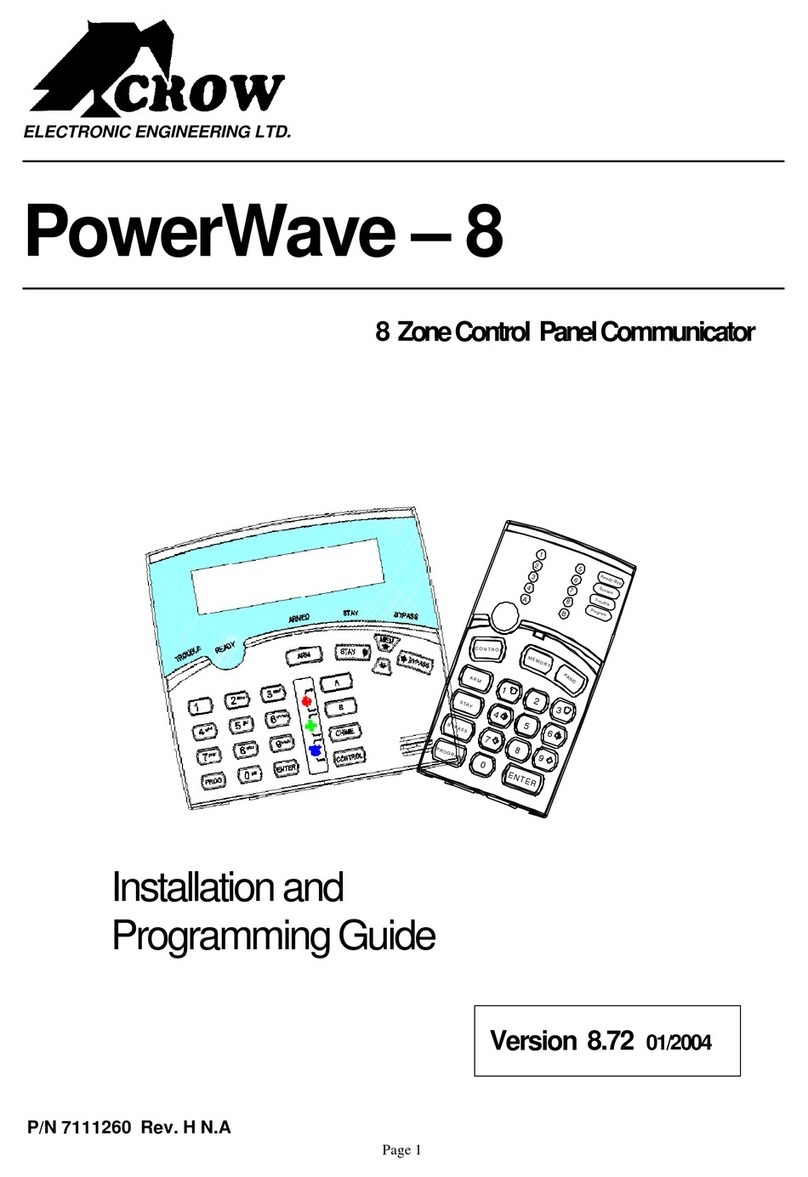
Crow PowerWave-8 Installation guide

