Crow Runner Series Operator's manual

ELECTRONIC ENGINEERING LTD
.
Runner Series
W
IRELESS AND
W
IRED
C
ONTROL
P
ANEL
Installation
and
Configuration Guide
by
byby
by CROW Electronic Engineering Ltd.
CROW Electronic Engineering Ltd.CROW Electronic Engineering Ltd.
CROW Electronic Engineering Ltd.

Runner 8 - PW8-16ST
IMPORTANT NOTICE
IMPORTANT NOTICEIMPORTANT NOTICE
IMPORTANT NOTICE
All information and data contained in this document is proprietary and
confidential. CROW Electronic Engineering Ltd. shall not be liable, in any event, for
any claims for damages or any other remedy in any jurisdiction whatsoever,
whether in an action in contract, tort (including negligence and strict liability) or
any other theory of liability, whether in law or equity including, without limitation,
claims for damages or any other remedy in whatever jurisdiction, and shall not
assume responsibility for patent infringements or other rights to third parties,
arising out of or in connection with this document.
Further, CROW Electronic Engineering Ltd. reserves the right to revise this
publication and to make changes to its content, at any time, without obligation to
notify any person or entity of such revision changes. These materials are
copyrighted and any unauthorized use of these materials may violate copyright,
trademark, and other laws. Therefore, no part of this publication may be
reproduced, photocopied, stored on a retrieval system, or transmitted without the
express written consent of CROW Electronic Engineering Ltd. Any new issue of this
document invalidates previous issues.
©CROW Electronic Engineering Ltd. 2005. All rights reserved.
Information in this document is subject to change without notice. No part of
this document may be reproduced or transmitted in any form or by any
means, electronic or mechanical, without express written permission of
CROW Electronic Engineering Ltd..
Document Version 1.00.005
Runner Series
JUNE 2005

i
CONTENTS
OVERVIEW........................................................................................................................... 1
C
ONNECTION
D
IAGRAMS
...........................................................................................................1
INPUT OPTIONS .................................................................................................................. 5
D
IFFERENT
I
NPUT
C
ONFIGURATIONS
............................................................................................5
Z
ONE
W
IRING
E
XAMPLES
...........................................................................................................6
O
THER
I
NPUTS
.......................................................................................................................8
OUTPUTS.............................................................................................................................. 9
D
ESCRIPTION OF
O
UTPUTS
........................................................................................................9
K
EYPAD
P
ORT
.........................................................................................................................9
E
XPANSION
P
ORT
..................................................................................................................10
ACCESSORIES.................................................................................................................... 11
R
ADIO
R
ECEIVER
...................................................................................................................11
V
OICE
B
OARD
.......................................................................................................................11
P
ROXIMITY
R
EADERS
..............................................................................................................12
P
ROXIMITY
R
EADERS
C
ONNECTIONS
...........................................................................................13
N
IGHT
M
ONITOR
K
EYPAD
........................................................................................................14
KEYPAD INDICATORS........................................................................................................ 16
LED K
EYPAD
........................................................................................................................16
LCD KEYPAD .....................................................................................................................21
KEYPAD ADDRESS ASSIGNMENT & INSTALLATION.......................................................... 23
LED K
EYPAD
........................................................................................................................23
LCD KEYPAD .....................................................................................................................24
A
DJUSTING
B
ACKLIGHTING AND
B
UZZER
T
ONE
..............................................................................25
LCD KEYPAD “LOCAL EDIT” MODE .................................................................................... 27
LCD K
EYPAD
.......................................................................................................................27
PROGRAM MODE ACCESS.................................................................................................. 35
A
CCESSING
P
ROGRAM
M
ODE
....................................................................................................35
E
XITING
P
ROGRAM
M
ODE
........................................................................................................36
SPECIAL KEYPAD FUNCTIONS........................................................................................... 45
A
RMING OR
D
ISARMING
T
WO
A
REAS AT A
K
EYPAD
.........................................................................45
LCD Q
UICK
V
IEW
M
ODE
.........................................................................................................45

Runner 8 - PW8-16ST
ii
T
OGGLE
C
HIME
M
ODE
O
N
/O
FF
.................................................................................................46
S
END
M
ANUAL
T
EST
C
ALL
.......................................................................................................46
M
ANUALLY
A
NSWER AN
I
NCOMING
C
ALL
......................................................................................46
PROGRAMMING USERS ..................................................................................................... 47
U
SER
C
ODES
........................................................................................................................47
U
SER
C
ODE
T
YPE
..................................................................................................................48
U
SER
A
REAS
........................................................................................................................48
U
SER
A
CCESS
O
PTIONS
...........................................................................................................50
U
SER
C
ODE
P
RIVILEGES
..........................................................................................................51
R
ADIO
U
SER
T
YPE
.................................................................................................................51
R
ADIO
U
SER
P
RIVILEGES
.........................................................................................................52
U
SER
T
IME
Z
ONE
A
SSIGNMENTS
................................................................................................52
U
SER TO
K
EYPAD
A
SSIGNMENT
.................................................................................................53
R
ADIO
P
ENDANT
P
ANIC
B
EEPS TO
K
EYPAD
...................................................................................53
U
SER TO
O
UTPUT
M
ASK
..........................................................................................................54
U
SER
C
AN
T
URN AN
O
UTPUT
ON
AND
OFF .................................................................................54
R
ADIO
P
ENDANT
P
ANIC
A
LARM TO
O
UTPUT
..................................................................................55
L
EARN
F
IND AND
D
ELETE
R
ADIO
K
EY
C
ODES AND
T
AGS
..................................................................55
MISCELLANEOUS PANEL & CLOCK SETTINGS................................................................... 59
I
NSTALLER
C
ODE
...................................................................................................................59
D
URESS
D
IGIT
......................................................................................................................59
D
IAL
R
EPORT
D
ELAY
..............................................................................................................59
R
ADIO
Z
ONE
S
UPERVISED
T
IMER
...............................................................................................59
T
WO
T
RIGGER
T
IMER
.............................................................................................................60
M
AINS
F
AIL
R
EPORTING
D
ELAY
.................................................................................................60
R
ECEIVER
F
AIL
D
ELAY
/T
IMER
...................................................................................................60
U
PLOAD
/D
OWNLOAD
S
ITE
C
ODE
N
UMBER
...................................................................................60
T
EMPORARY
O
UTPUT
D
ISABLE
..................................................................................................60
M
ISCELLANEOUS
I
NSTALLER AND
P
ANEL
O
PTIONS
..........................................................................61
H
IDE
U
SER
C
ODES
- USER OPTIONS.......................................................................................63
S
ETTING
T
IME
, D
ATE AND
D
AYLIGHT
S
AVING
..............................................................................64
D
AYLIGHT
S
AVING
(DLS) S
ETTINGS
..........................................................................................64
OUTPUTS............................................................................................................................ 65
OUTPUT OPTIONS.............................................................................................................65
O
UTPUT
O
N
D
ELAY
, P
ULSE
, R
ESET AND
C
HIME
T
IMES
....................................................................69
O
UTPUT
V
OICE
B
OARD
R
EMOTE
C
ONTROL
S
TART
M
ESSAGES
............................................................70
U
N
-M
AP AN
O
UTPUT
..............................................................................................................70

Overview
iii
A
SSIGNING A
T
IME
-Z
ONE TO AN
O
UTPUT
....................................................................................70
AREAS................................................................................................................................ 71
A
REA
A
RM AND
S
PECIAL
F
UNCTION
O
PTIONS
...............................................................................71
A
REA
A
RM
/S
TAY
P
ULSE
& C
HIRPS TO
O
UTPUTS
............................................................................73
M
ONITORING
A
CCOUNT
C
ODE
N
UMBER
.......................................................................................76
R
EMOTE
A
RM
/D
ISARM
DTMF C
ODE
& S
TART
V
OICE
M
ESSAGE
........................................................78
A
REA
D
ELINQUENCY
D
ELAY
......................................................................................................79
A
UTOMATIC
A
RM
/D
ISARM
T
IME
Z
ONE
........................................................................................79
KEYPADS............................................................................................................................ 80
K
EYPAD
A
REA
A
SSIGNMENT
......................................................................................................80
K
EYPAD
B
UTTON
O
PERATIONS
, M
ISC
. B
EEPS AND
LED C
ONTROL
......................................................80
K
EYPAD
A
RM
, S
TAY
, A
AND
B B
UTTON
O
PTIONS
..........................................................................82
K
EYPAD TO
O
UTPUT
M
ASK
.......................................................................................................87
<C
ONTROL
> B
UTTON TO
O
UTPUT
M
ASK
....................................................................................87
K
EYBOARD
P
ANIC
, F
IRE AND
M
EDICAL
A
LARMS TO
O
UTPUTS AND
KP B
UZZER
......................................88
K
EYPAD
C
HIME
T
IMER
............................................................................................................90
P
ROXIMITY
R
EADER
O
PTIONS
...................................................................................................90
KEY-SWITCHES.................................................................................................................. 92
K
EY
-S
WITCH
A
REA
A
SSIGNMENT
...............................................................................................92
K
EY
-S
WITCH
A
RM
/D
ISARM
O
PTIONS
..........................................................................................92
ZONES................................................................................................................................ 95
Z
ONE
A
REA
A
SSIGNMENT
........................................................................................................95
Z
ONE
A
LARM
T
YPE
O
PTIONS
....................................................................................................95
Z
ONE
EOL (E
ND
-O
F
-L
INE
) O
PTIONS AND
V
IBRATION
S
ETTINGS
.......................................................98
R
ADIO
Z
ONE
D
ETECTOR
T
YPE
................................................................................................100
Z
ONE
A
LARMS TO
O
UTPUT AND
K
EYBOARD
B
UZZER
M
APPING
.........................................................102
Z
ONE
CID R
EPORT
C
ODES
....................................................................................................106
A
RMED AND
S
TAY
M
ODE
E
NTRY
D
ELAY
T
IMES
............................................................................108
Z
ONE
W
ATCH
D
OG
T
IMER
.....................................................................................................108
L
EARN
/F
IND AND
D
ELETE
R
ADIO
Z
ONE
C
ODES
...........................................................................109
TIME ZONES..................................................................................................................... 110
H
OLIDAYS
.........................................................................................................................110
T
IME
Z
ONE
D
AYS
................................................................................................................110
T
IME
Z
ONE
S
TART AND
S
TOP
T
IMES
........................................................................................111
DIALLER........................................................................................................................... 113
D
IALLER
O
PTIONS
...............................................................................................................113

Runner 8 - PW8-16ST
iv
A
UTO
A
NSWER
R
ING COUNT
...................................................................................................116
T
EST
C
ALL OPTIONS
.............................................................................................................116
K
EYPAD
L
ISTEN
-I
N AND
O
UTPUT
O
PTIONS
.................................................................................116
D
IALLING
P
RE
-F
IX
N
UMBER
...................................................................................................117
K
EYPAD
P
ANIC
, F
IRE AND
M
EDICAL
A
LARMS
CID R
EPORT
C
ODE
.....................................................117
O
UTPUT
, M
ICROPHONE
&V
OICE
K
ISS
OFF DTMF R
EMOTE
C
ODES
.................................................117
M
ISCELLANEOUS
V
OICE
R
EPORTING
M
ESSAGE
N
UMBERS
...............................................................119
TELEPHONE NUMBERS .................................................................................................... 121
P
ROGRAMMING
T
ELEPHONE
N
UMBERS
.......................................................................................121
R
EPORTING
F
ORMATS
...........................................................................................................121
TELEPHONE NUMBER REPORT OPTIONS ..........................................................................123
M
AXIMUM
D
IAL
R
E
-T
RIES PER
T
ELEPHONE
N
UMBER
.....................................................................124
D
IAL
P
ROGRESS
O
PTIONS
......................................................................................................125
C
ALL
D
IVERT
N
UMBERS
& O
PTIONS
.........................................................................................128
C
ALL
D
IVERT
N
UMBERS
& O
PTIONS
.........................................................................................129
4+2 PROGRAM OPTIONS................................................................................................. 131
U
SING THE
4+2 C
ODES
........................................................................................................131
M
AINS
/B
ATTERY
/T
AMPER
/D
URESS
& A
RMING
4+2 C
ODES
...........................................................132
DIAGNOSTIC & DEFAULT OPTIONS................................................................................. 134
D
ISPLAY
S
OFTWARE
V
ERSION
, K
EYPAD
N
UMBER AND
K
EYPAD
A
REAS
................................................134
D
ISPLAY
A
CTIVE
T
IME
Z
ONES
& B
ATTERY
V
OLTAGE
.....................................................................134
S
TART
W
ALK
T
EST
M
ODE
......................................................................................................134
R
EAD OR
W
RITE TO THE
DTU ................................................................................................135
R
ESTORE
D
EFAULTS
.............................................................................................................135
C
LEAR
M
EMORY
B
UFFER
........................................................................................................135
S
TART A
C
ALL
-B
ACK
C
ALL
......................................................................................................135
USER PRIVILEGES CHART ............................................................................................... 137
T
ELECOM
I
NTERFACE
............................................................................................................138
CONTACT ID CODE SUMMARY......................................................................................... 140
SOFTWARE CHANGE UPDATE NOTICE............................................................................. 142
PW8/16 QUICK START GUIDE......................................................................................... 143
PW8/16 CONFIGURATION SUMMARY GUIDE................................................................. 144
U
SERS
..............................................................................................................................145
M
ISCELLANEOUS
P
ANEL
& C
LOCK
S
ETTINGS
...............................................................................149
O
UTPUTS
..........................................................................................................................151
A
REAS
..............................................................................................................................152

Overview
v
K
EYPADS
...........................................................................................................................156
K
EY
-S
WITCHES
...................................................................................................................162
Z
ONES
..............................................................................................................................162
T
IME
Z
ONES
......................................................................................................................170
D
IALLER
............................................................................................................................171
T
ELEPHONE
N
UMBERS
...........................................................................................................173
M
ISCELLANEOUS
4+2 P
ROGRAM
O
PTIONS
.................................................................................176
P
ANEL
D
IAGNOSTIC
& D
EFAULT
O
PTIONS
..................................................................................178
CROW ELECTRONIC ENGINEERING LTD. (C
ROW
) WARRANTY POLICY CERTIFICATE ...........179
HOW TO CONTACT US...................................................................................................... 180


Overview
1
Overview
OverviewOverview
Overview
Connection Diagrams
Connection DiagramsConnection Diagrams
Connection Diagrams
Runner 8
Runner 8Runner 8
Runner 8
The Runner 8 board can fit in 3 cases : PW-housing ,MINI-housing ,COMPACT housing .
On the compact housing it equipped with transformer 20VA .
On the Mini-housing and PW-housing it’s equipped with transformer 25VA .
Battery Spec
Battery SpecBattery Spec
Battery Spec.: Sealed Lead-Acid Rechargeable Battery 12V/1.3Ah up to 12V /7Ah at case of
Mini-housing and PW-housing
Battery Cutoff Level : not fitted

Runner 8 - PW8-16ST
2
Runner Plus
Runner PlusRunner Plus
Runner Plus
The Runner Plus board is fit into the Compact Box and it’s equipped with transformer 20VA.
The Runner Plus can also be fed from an eternal adaptor 100-240V AC /14.4V DC ,1A.
According to customer request.
Battery Spec
Battery SpecBattery Spec
Battery Spec.: Sealed Lead-Acid Rechargeable Battery 12V/1.3Ah.
Battery Cutoff Level : (When AC mains fails) : 7V to 7.6 V

Overview
3
WCP PRO
WCP PROWCP PRO
WCP PRO
The WCP board is fitted into the WCP Housing and is equipped with a 15VA transformer.
The WCP Pro can also be fed from an external adaptor 100-240V AC /14.4V DC ,1A.
According to customer request.
Battery Spec
Battery SpecBattery Spec
Battery Spec.: Sealed Lead-Acid Rechargeable Battery 12V/1.3Ah.
Battery Cutoff Level : (When AC mains fails) : 7V to 7.6 V.


Input Options
5
Input Options
Input OptionsInput Options
Input Options
Different Input Configurations
Different Input ConfigurationsDifferent Input Configurations
Different Input Configurations
The Runner 8 has nine separate programmable monitored analogue inputs,
8 x Programmable, multi-state detection inputs
1 x Programmable tamper input ( with optional Key-switch functions)
NOTE
NOTENOTE
NOTE
Each input must be terminated with the appropriate value or combination of
end-of-line resistors, even if the input is unused.
Zone Inputs
Zone InputsZone Inputs
Zone Inputs
Each of the 8 zone inputs can be assigned one of the following End of Line (EOL)
configuration options,
Zone EOL Type (P125E)
Zone EOL Type (P125E)Zone EOL Type (P125E)
Zone EOL Type (P125E)
Input Resistor
Input ResistorInput Resistor
Input Resistor
Comments
CommentsComments
Comments
0 (Short circuit) Loop EOL
1 1k (Brown, Black, Red) Single EOL
2 1k5 (Brown, Green, Red) Single EOL
3 2k2 (Red, Red, Red) Single EOL
4 3k3 (Orange, Orange, Red) Single EOL
5 3k9 (Orange, White, Red) Single EOL
6 4k7 (Yellow, Violet, Red) Single EOL
7 5k6 (Green, Blue, Red) Single EOL
8 6k8 (Blue, Grey, Red) Single EOL
9 10k (Brown, Black, Orange) Single EOL
10 12k (Brown, Red, Orange) Single EOL
11 22k (Red, Red, Orange) Single EOL
12 2k2 Tamper, 4k7 Zone Zone & Tamper
13 3k3 Tamper, 6k8 Zone Zone & Tamper
14 2k2 Tamper, 4k7 Low Zone,
8k2 High Zone Zone Doubling, with Tamper
15 4k7 Low Zone, 8k2 High Zone Zone Doubling, No tamper

Runner 8 - PW8-16ST
6
Zone Wiring Examples
Zone Wiring ExamplesZone Wiring Examples
Zone Wiring Examples
Type 0 (Short/Loop Circuit)
Type 0 (Short/Loop Circuit)Type 0 (Short/Loop Circuit)
Type 0 (Short/Loop Circuit)
Type 1
Type 1Type 1
Type 1-
--
-11 (Single EOL no Tamper)
11 (Single EOL no Tamper)11 (Single EOL no Tamper)
11 (Single EOL no Tamper)
Type 12
Type 12Type 12
Type 12-
--
-13 (Single Zone with Tamper)
13 (Single Zone with Tamper)13 (Single Zone with Tamper)
13 (Single Zone with Tamper)
Type 14 (Zone Doubling with Tamper)
Type 14 (Zone Doubling with Tamper)Type 14 (Zone Doubling with Tamper)
Type 14 (Zone Doubling with Tamper)
Short circuit loop, No EOL
Short circuit loop, No EOLShort circuit loop, No EOL
Short circuit loop, No EOL

Input Options
7
2k2 EOL, No Tamper
2k2 EOL, No Tamper2k2 EOL, No Tamper
2k2 EOL, No Tamper
Type 12 Configuration
Type 12 ConfigurationType 12 Configuration
Type 12 Configuration
Alarm & Tamper monitoring (contacts can be N/C or N/O).
Type 15 Configuration
Type 15 ConfigurationType 15 Configuration
Type 15 Configuration
Zone Doubling, NO Tamper (contacts can be N/C or N/O).
Wiring a PIR Detector (N/C) for Alarm & Tamper
Wiring a PIR Detector (N/C) for Alarm & TamperWiring a PIR Detector (N/C) for Alarm & Tamper
Wiring a PIR Detector (N/C) for Alarm & Tamper
Monitoring
MonitoringMonitoring
Monitoring

Runner 8 - PW8-16ST
8
Other Inputs
Other InputsOther Inputs
Other Inputs
Tamper
TamperTamper
Tamper
A 24Hr tamper circuit is available for monitoring system tampers. This Tamper circuit is
programmable as either normally closed loop or 2k2 EOL supervision (the default is usually a
closed loop). Any Tamper alarms on this input are mapped to alarm outputs in the same
manner as for detection zones 1-16. Using Dual-End-of-Line resistors (Refer to Zone Type 15
on Page 6) the Tamper input can also provide two key-switches. The Low key-switch (4k7
resistor) will be Key-switch 1 while the High key-switch (8k2 resistor) will be Key-switch 2.
In addition to the Zone & Tamper inputs, you will find the following additional inputs on the
control PCB;
AC
ACAC
AC
Connect the two low voltage wires (no polarity) from the transformer to the terminals
marked AC on the PCB. The panel includes a mains transformer rated at 15.5VAC.
Earth
EarthEarth
Earth
-
--
- not used
not usednot used
not used
In case of using metal box connect the mains earth to the appropriate terminal on the mains
terminal block in the control box cabinet. Also connect a lead from this earth point to the
terminal marked with the Earth symbol (next to AC terminals) on the panel PCB.
Battery
BatteryBattery
Battery
Connect a sealed lead acid rechargeable 12VDC battery to the terminals labelled red and
black on the control panel being careful to observe the correct polarity. The maximum
recommended battery capacity is 7 amp hours. Battery charge current at these terminals is
limited to 260mA maximum. The battery connection is protected against short circuits by a
thermal fuse (F1). The panel performs a dynamic load test on the battery every 15 seconds
and if it fails the test at any time it will flash the Battery LED.
Line In
Line InLine In
Line In
These terminals are used to connect the panel to the incoming telephone line. The dialler
uses this line for reporting alarm events.
Line Out
Line OutLine Out
Line Out
These terminals are used to connect telephones and other communication equipment to the
incoming phone line via the panel dialler circuit. The telephone line is passed through the
controller to ensure that the line is available to the controller when it is required.

Outputs
9
Outputs
OutputsOutputs
Outputs
Description of Outputs
Description of OutputsDescription of Outputs
Description of Outputs
12 Volt Outputs
12 Volt Outputs12 Volt Outputs
12 Volt Outputs
There are three 12VDC outputs on the panel PCB. These 12 volt outputs are regulated and
Thermal fuse protected against short circuits. The accessory outputs are marked 12V and
0V, while the keypad buss 12V supply is labelled “POS” & “NEG”. The 12V outputs are
supplied by thermal fuses F2 & F3. The recommended maximum total load that should be
drawn from all of the 12V outputs during an
alarm is 1A.
Outputs 1 & 2
Outputs 1 & 2Outputs 1 & 2
Outputs 1 & 2
These fully programmable, high current, open drain (high-going-low) type FET outputs
capable of switching up to 1.5A @ 12VDC. These 2 outputs are normally set as switched
outputs, providing power for 12V sirens or piezos. If required, these outputs can be
programmed to be siren outputs designed to drive an 8 ohm 10 watt horn speaker on each
output (see P37E option 1). Also if a horn speaker is connected to Output #1 you may
select (Refer to P175E 7E program address) the listen-in feature to this output as well so
that the dialling sequence can be heard at the speaker.
Output 3 & 4
Output 3 & 4Output 3 & 4
Output 3 & 4
This is a low current, open drain (high-going-low) type FET outputs capable of switching up
to 500mA. Like Outputs 1 & 2 it is fully programmable.
NOTE
NOTENOTE
NOTE
Connecting devices which draw current in excess of 500mA to output 3/4 can
damage the output.
Relay Out
Relay OutRelay Out
Relay Out
This is a relay is related to Output 4 with single pole changeover contacts. If required, the
Common (C) contact of the relay is connected by default to GND via JUMPER, the jumper can
be selected to 12V or removed.
Keypad Port
Keypad PortKeypad Port
Keypad Port
The terminals marked POS, NEG, CLOCK, & DATA make up the communications port which
the keypads and other intelligent field devices use to talk to the controller. The terminals are
connected to corresponding terminals on the remote devices. The "lin" terminal is only used
by the keypads and utilises a fifth wire to provide a communicator “listen-in” facility. This
feature is particularly useful when servicing monitoring faults. The keypad 12V supply
(POS,NEG) is protected by fuse F3.

Runner 8 - PW8-16ST
10
Expansion Port
Expansion PortExpansion Port
Expansion Port
The expansion port allows connection of the RS232 serial board, 90 second Voice Board,
DTMF Board or EEPROM data transfer board (DTU). The serial board allows direct connection
of a PC running the Upload/Download software. The 90 second voice board allows voice
messages to be programmed for monitoring purposes. The Voice & DTMF boards allow
Touchtone Code remote control via a telephone. The DTU allows for program “Cloning” from
one panel to another.

Accessories
11
Accessories
AccessoriesAccessories
Accessories
Radio Receiver
Radio ReceiverRadio Receiver
Radio Receiver
The panel can have wireless capability via the FW-RCVR receiver module. The receiver will
add wireless capability to your system in the form or wireless PIR detectors, Wireless Radio-
key transmitters and wireless reed switch transmitters.
The FW-RCVR connects to the same communications port as the keypads. The FW-RCVR is
available in 3 frequencies, 915MHz,433MHz,868MHz. Multiple FW-RCVR can be connected to
the panel to increase the coverage range if desired.
The green LED fitted to the FW-RCVR receiver will flash at 1 second intervals when in
"Learn" mode (see P18E & P164E). The LED will also turn on when it is receiving an actual
radio transmission (On Steady).
Voice Board
Voice BoardVoice Board
Voice Board
The panel can also be fitted with a 90 second Voice Board or DTMF module. The Voice board
stores either alarm event messages for Voice dial monitoring and /or status messages for
use with Command Control. The DTMF board provides decoding of keypad numeric entries
from a remote telephone. The panel Voice or DTMF Boards are installed directly onto the
motherboard via the "SERIAL" socket.
Installation procedure for the Voice or DTMF Board module is as follows.
1. Power-down the panel fully before starting the installation procedure.
2. Carefully plug the Voice or DTMF Board into the SERIAL socket (it will only fit in one
direction).
3. Power-up the panel.
Speech message programming
Once you have installed the Voice Board you can record your personalised speech messages
into the module with the speech programmer (the programmer plugs onto the 10 way strip
connector on the voice board).
Before programming your voice messages you should work out a list of the messages you
would like to be sent for each alarm type and write them down in order, giving them a
message number. These messages should then be recorded in the same order they are
written down so you know what the message number is letter when programming alarms to
messages.
To record your messages once the programmer is installed, first press the reset button on
the side of the Voice Board, then hold the programmer about 10 cm away from the mouth
and speak clearly at normal level into the microphone while holding down the "REC" button.
When you reach the end of your message release the REC button. (NOTE: Each individual
message must be longer that 2 seconds duration). When recording your voice alarm
message, you must ensure that you clearly identify the origin of the call. You can play the
message back through the programmer by first pressing the reset button then by pressing
the "PLAY" button momentarily. Because the panel can address many individual voice
messages you must store individual messages at what is known as recording slots within the
Voice Board. These recording slots are recorded sequentially, one message starting where
the other finishes. Every time you press and release the REC button on the programmer,

Runner 8 - PW8-16ST
12
you create an end of message marker. These markers are used to define the recording slots
within the Voice Board and can be of varying length according to each message duration.
To re-record your messages you must first press the "RESET" button on the speech module
to get back to recording slot # 1. Once you are at slot # 1 you can re-record your messages
in order as required.
NOTE
NOTENOTE
NOTE
When recording multiple messages you only press the “RESET” button once at
the beginning then record all messages sequentially as stated above. When
you have finished recording all of your messages you can then press the
“RESET” button to allow play-back of the recording messages for verification
purposes.
When you have finished recording your alarm messages, unplug the programmer and the
process is complete. You must now go to the program addresses and assign the individual
messages to the specific functions.
Proximity Re
Proximity ReProximity Re
Proximity Readers
adersaders
aders
There are three proximity readers that can be connected to the control panel. They are;
!
PW-Reader 2K: For arm/disarm area A and/or B.
!
PW-Reader(without keys): For arm/disarm one area A.
!
PW-Reader FK :Proximity and keypad (PIN) Access Reader.
The PW-Reader 2K is generally to be used for selective arming or disarming of either Area
“A” or “B” or both. By presenting a valid access tag or card to the reader the user can then
arm or disarm the panel using the “A” & “B” buttons on the reader. On presenting a valid tag
to the reader, the current status of Areas A & B will be shown on the two LED’s. The user has
4 seconds to make a new selection before the reader will timeout and the tag will have to be
re-presented again. The Areas allowed to be controlled by the user must be programmed by
the installer. If the User is allowed to fully Arm or arm Stay Mode then they can cycle
through the various states (eg Disarmed, Full Armed, Stay Armed). As the “A” or “B” button
is pressed the associated LED will change to indicate the new state, eg if the Disarmed state
was selected the LED will be GREEN, If the Armed state was selected the LED will be RED
and if Stay Mode was selected the LED would be flashing RED. Four seconds after the last
button was pressed the reader will action the new armed status and the LED’s will turn off. If
the reader has also been programmed to allow the “1& 3 PANIC” function at that keypad
number a “PANIC” alarm will be generated if the “A” & “B” buttons are pressed
simultaneously (see P72E option 5).
NOTE
NOTENOTE
NOTE
From the disarmed state you can select Armed or Stay modes but if already
Armed or in Stay Mode you MUST disarm first (letting the reader timeout)
before you can select a new armed state.
The PW-Reader(without keys ) is generally going to be used as an access control reader
although if the tag is allowed to Arm/Disarm the alarm then this will also happen when the
tag is presented. For access control, if a tag or card is presented to the reader the associated
door lock will release via an output on the control panel. There is also an output at the
reader which can be used to unlock the door if desired (see drawing on following page for
details). The output number at the reader follows the keypad address number, eg if the
reader has been assigned to keypad address 5, the output at the reader will follow all
programming associated with output 5.
The PW-Reader FK is generally going to be used as an access control reader as well
although if the tag is allowed to Arm/Disarm the alarm then this will also happen when the
tag is presented. This reader combines a proximity reader with a full keypad. Depending on
program options the reader can be set-up to operate on a proximity tag or card only, on
Other manuals for Runner Series
4
Table of contents
Other Crow Control Panel manuals

Crow
Crow PowerWave-8 Installation guide

Crow
Crow Arrowhead Elite V6 Operating instructions

Crow
Crow PowerWave - 64 Operating instructions

Crow
Crow serenity User manual
Crow
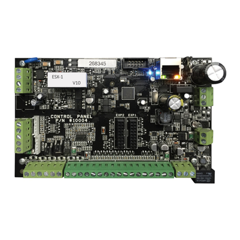
Crow RUNNER-8 Operating instructions
Crow
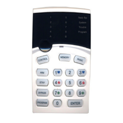
Crow PowerWave 8 User manual

Crow
Crow Runner Series Operator's manual

Crow
Crow RUNNER 8/64 Operating instructions

Crow
Crow Power Wave - 8 User manual

Crow
Crow PowerWave-64 Installation guide

