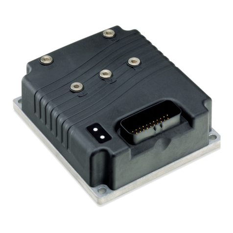
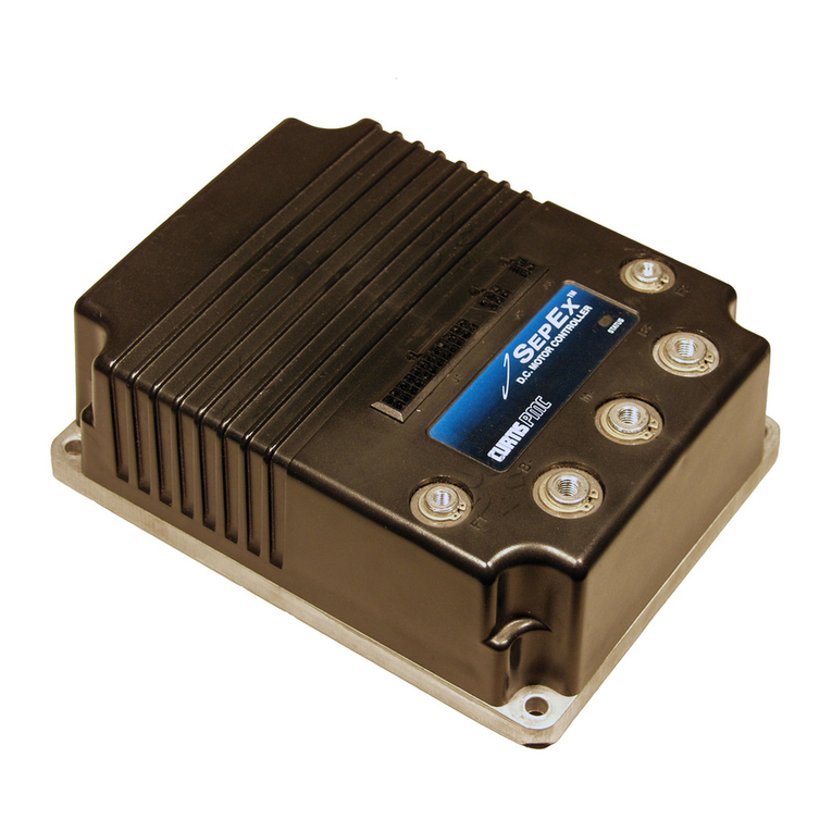
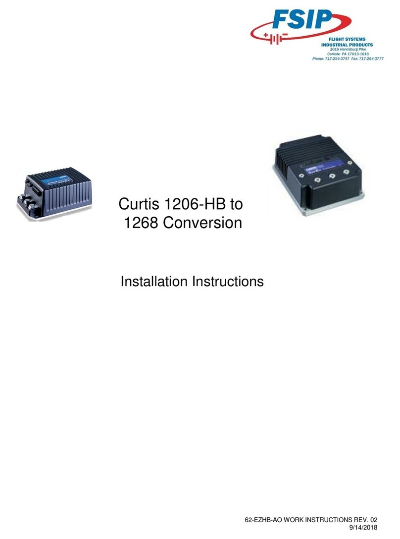
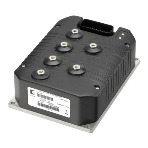
Curtis MultiMode 1228 User manual

Manual
Model 1228
MultiMode™ Motor Controller
Read Instructions Carefully!
Specifications are subject to change without notice.
© 2011 Curtis Instruments, Inc. ® Curtis is a registered trademark of Curtis Instruments, Inc.
© The design and appearance of the products depicted herein are the copyright of Curtis Instruments, Inc. 36149 Rev F 10/11
Curtis Instruments, Inc.
200 Kisco Avenue
Mt. Kisco, NY 10549
www.curtisinstruments.com


Curtis 1228 Manual, Rev. F iii
CONTENTS
1. OVERVIEW ...............................................................................1
2. INSTALLATION AND WIRING .............................................4
Mounting the Controller .....................................................4
Connections: High Current ................................................5
Connections: Low Current .................................................5
Wiring: Applications with Seat Lift ....................................6
Wiring: Applications without Seat Lift ...............................8
Throttle Wiring .................................................................10
5kΩ, 3-wire potentiometer throttle ............................10
5V throttle .................................................................10
Curtis ET-XXX electronic throttle .............................11
Speed limit pot ...........................................................12
Switches and Other Hardware ...........................................12
Keyswitch ...................................................................12
Push switch ................................................................12
Brake release switch ....................................................13
Inhibit ........................................................................13
Status LED ................................................................13
Battery discharge indicator .........................................14
Horn ..........................................................................14
Circuitry protection devices .......................................14
Seat lift switch ............................................................14
3. PROGRAMMABLE PARAMETERS .......................................15
Motor Parameters ..............................................................17
Main Current Limit ...................................................17
Motor Resistance ........................................................17
Acceleration Parameters .....................................................17
Maximum-Speed Forward Acceleration Rate ..............17
Minimum-Speed Forward Acceleration Rate ..............17
Maximum-Speed Reverse Acceleration Rate ...............18
Minimum-Speed Reverse Acceleration Rate ...............18
Gear Soften ................................................................18
Soft Start ....................................................................18
Braking Parameters ............................................................19
Maximum-Speed Forward Deceleration Rate .............19
Minimum-Speed Forward Deceleration Rate .............19
Emergency Stop Deceleration Rate ............................19
Maximum-Speed Reverse Deceleration Rate ..............19
Minimum-Speed Reverse Deceleration Rate ..............20
CONTENTS

iv Curtis 1228 Manual, Rev. F
CONTENTS
Key-Off Deceleration Rate .........................................20
Brake Delay ................................................................20
Speed Parameters ...............................................................20
Maximum Speed, M1/M2 .........................................20
Minimum Speed, M1/M2 ..........................................21
Maximum Reverse Speed, M1/M2 .............................21
Minimum Reverse Speed ...........................................21
Creep Speed ...............................................................21
Push Speed .................................................................21
IR Compensation .......................................................22
Speed Scaler ...............................................................22
Throttle Parameters ...........................................................22
Throttle Input Signal Type .........................................22
Throttle Autocalibration ............................................23
Throttle Deadband ....................................................23
Throttle Gain .............................................................25
Ramp Shape (Static Throttle Map) ............................26
Fault Parameters ................................................................27
High Pedal Disable (HPD) ........................................27
Brake Faults ...............................................................28
Seat Lift Brake Faults .................................................28
Fault Beep ..................................................................28
Other Parameters ...............................................................28
Seat Lift .....................................................................28
Virtual Seat Lift .........................................................29
Beeper Solid ...............................................................29
BDI Full Voltage ........................................................29
BDI Empty Voltage ....................................................29
BDI Reset Voltage ......................................................30
Sleep Delay ................................................................30
Tremor Compensation ...............................................30
4. INITIAL SETUP ......................................................................31
Beginning the Setup Procedures ........................................31
Throttle .............................................................................31
Basic Vehicle Checkout ......................................................33
Determining Motor Resistance ..........................................33
5. VEHICLE PERFORMANCE ADJUSTMENT .......................34
Setting the Maximum Speeds ............................................34
Setting the Acceleration and Deceleration Rates ................34
Adjusting Load Compensation ..........................................37
Fine-Tuning the Vehicle’s Response Smoothness ................38
Curtis 1228 Manual, Rev. F v
6. PROGRAMMER MENUS ......................................................40
1228 Parameters Menu ......................................................40
1228 Monitor Menu .........................................................42
1228 Faults and Fault History ...........................................42
7. DIAGNOSTICS AND TROUBLESHOOTING ....................43
Programmer Diagnostics ....................................................43
LED Diagnostics ...............................................................43
Troubleshooting Chart ......................................................45
8. MAINTENANCE ....................................................................46
APPENDIX A Vehicle Design Considerations Regarding
Electromagnetic Compatibility (EMC)
and Electrostatic Discharge (ESD) .....................A-1
APPENDIX B Curtis WEEE & RoHS Statement .....................B-1
APPENDIX C Programming Devices ....................................... C-1
APPENDIX D Index to Programmable Parameters ................... D-1
APPENDIX E Specifications ......................................................E-1
CONTENTS

vi Curtis 1228 Manual, Rev. F
FIGURES
FIG. 1: Curtis 1228 electronic motor controller ....................................1
FIG. 2: Mounting dimensions, Curtis 1228 controller .........................4
FIG. 3a: Standard wiring configuration, with seat lift .............................6
FIG. 3b: Alternative wiring configuration, with seat lift ..........................7
FIG. 4a: Standard wiring configuration, without seat lift ........................8
FIG. 4b: Alternative wiring configuration, without seat lift .....................9
FIG. 5: Wiring for 5KΩ, 3-wire potentiometer ..................................10
FIG. 6: Wiring for 5V throttle ............................................................11
FIG. 7: Wiring for Curtis ET-XXX electronic throttle ........................11
FIG. 8: Wiring to inhibit operation during battery charging ..............13
FIG. 9: Effect of adjusting the neutral deadband parameter ................24
FIG. 10: Effect of adjusting the throttle gain parameter ........................25
FIG. 11: Ramp shape (throttle map) for controller
with maximum speed set at 100% ..........................................26
FIG. 12: Ramp shape (throttle map) for controller
with maximum speed set at 60% ............................................27
TABLES
TABLE 1: Programmable throttle input signal types ..........................22
TABLE 2: Status LED fault codes ......................................................45
TABLE 3: Troubleshooting chart .......................................................46
TABLE D-1: Parameter index .............................................................. D-1
TABLE E-1: Specifications, 1228 controller ........................................E-1
FIGURES / TABLES

Curtis 1228 Manual, Rev. F 1
1 — OVERVIEW
OVERVIEW
The Curtis 1228 MultiMode™ controller is a permanent magnet motor speed
controller designed for use in mobility aid scooters and other small electric
vehicles, such as sweeper/scrubbers. It offers smooth, silent, cost effective
control of motor speed and torque. A four quadrant, full bridge power output
stage provides for solid state motor reversing and full braking power without
additional relays or contactors.
The 1228 controller is fully programmable by means of a Curtis pro-
gramming device. Use of the programmer offers diagnostic and test capability
as well as configuration flexibility.
1
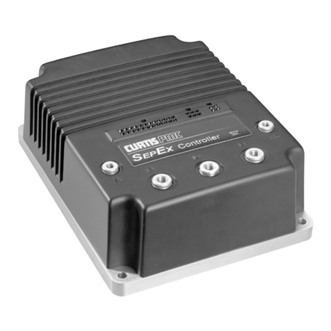
Fig. 1 Curtis 1228
MultiMode™ electronic
motor controller.
Like all Curtis motor controllers, the 1228 offers superior operator control
of the vehicle’s motor drive speed. In addition, the 1228 controls the seat lift
motor if one is used. Features include:
✓ Full bridge power MOSFET design, providing
• infinitely variable forward, reverse, drive, and brake control
• silent high frequency operation
• high efficiency
✓ Programmability through the Curtis programming device
✓ Complete diagnostics through the Curtis programmer and a status
LED
✓ Full compliance with all applicable international standards
More Features ☞

2 Curtis 1228 Manual, Rev. F
1 — OVERVIEW
✓ Available for single-ended or wigwag 5kΩ potentiometer throttles and
5V throttles (both standard full stroke and restricted range)
✓ MultiMode™ input selects between two different operating modes,
thus allowing optimization of vehicle characteristics for different driv-
ing conditions (for example, indoor/outdoor)
✓ Speed limit input provides linear variable speed limiting when an exter-
nal speed limit pot is used
✓ Current limiting in both driving and regenerative braking modes
✓ Load compensation stabilizes speed on ramps and over obstacles
✓ Speed scaler eliminates variations in maximum speed that would other-
wise result from variations in battery charge levels
✓ High pedal disable (HPD) function with lockout monitors status of
the throttle during turn-on and prevents operation until the throttle
has been returned to neutral
✓ Key-off deceleration function provides a controlled deceleration if the
keyswitch is turned off while driving
✓ “E Stop” provides a faster deceleration for emergency stops
✓ Seat lift function simplifies the wiring required to implement seat lift
in DME scooter applications
✓ Comprehensive fault detection monitors main contactor, output stage,
throttle demand vs. output, etc., and disables the drive functions if any
conditions are outside specified limits
✓ ISO 7176 compliant throttle fault detection circuitry inhibits driving if
throttle pot signal goes out of range for any reason
✓ Missing/shorted brake detection forces neutral in the event of an open
or shorted brake circuit
✓ Anti-rollback/anti-roll-forward function sets brake delay according to
speed and direction for improved braking response and minimized roll-
back on hills, etc.
✓ Reverse beeper option can be used to drive a low current dc horn when
vehicle is in reverse
✓ “Push” input electrically releases brake for key-on pushing (requires
that the vehicle be stopped first)
✓ “Push-Too-Fast” feature guards against unpowered vehicle runaway by
powering up and regulating motor voltage to limit vehicle speed
✓ Inhibit input disables the controller and puts the vehicle in a safe state
during charging, etc.

Curtis 1228 Manual, Rev. F 3
✓ Power saver deactivates the main relay after 25 seconds of non-
operation and deactivates the entire controller after the programmed
sleep delay has elapsed
✓ BDI output can be used to provide data to a voltmeter; the BDI
output can be “stuffed” (optional) in order to display the battery state
of charge during battery charging even while the keyswitch is turned
off
✓ Undervoltage cutback function protects against operation at low
battery voltage
✓ Overvoltage protection shorts the motor and disables driving in the
event of excessive battery voltage
✓ Thermally protected
✓ Reverse polarity protected (battery input)
Familiarity with your Curtis controller will help you install and operate it prop-
erly. We encourage you to read this manual carefully. If you have questions,
please contact the Curtis office nearest you.
1 — OVERVIEW
Working on electric vehicles is potentially dangerous. You should pro-
tect yourself against runaways, high current arcs, and outgassing from lead
acid batteries:
RUNAWAYS — Some conditions could cause the vehicle to run out of control.
Disconnect the motor or jack up the vehicle and get the drive wheels off the
ground before attempting any work on the motor control circuitry. Note:
If the wrong combination of throttle and switch styles is selected with the
programming device, the vehicle may suddenly begin to move.
HIGH CURRENT ARCS — Electric vehicle batteries can supply very high power,
and arcs can occur if they are short circuited. Always open the battery circuit
before working on the motor control circuit. Wear safety glasses, and use
properly insulated tools to prevent shorts.
LEAD ACID BATTERIES — Charging or discharging generates hydrogen gas,
which can build up in and around the batteries. Follow the battery man-
ufacturer’s safety recommendations. Wear safety glasses.
☞
CAUTION

4 Curtis 1228 Manual, Rev. F
INSTALLATION AND WIRING
MOUNTING THE CONTROLLER
The 1228 controller can be oriented in any position, but the location should
be carefully chosen to keep the controller clean and dry. If a clean, dry
mounting location cannot be found, a cover must be used to shield the
controller from water and contaminants.
The outline and mounting hole dimensions are shown in Figure 2. The
controller should be mounted by means of the two mounting holes at the op-
posing corners of the heatsink, using M4 × 20 mm (#8 × 0.75") screws.
This will give 6 mm (0.25") of exposed screw, which can be increased according
to the thickness of the mounting site.
2
2 — INSTALLATION & WIRING
Fig. 2 Mounting
dimensions, Curtis 1228
controller.
Dimensions in millimeters and (inches)
B+ B- M2 M1 LOGIC PROG
4.8 (0.19) dia., 2 plcs
156 (6.13)
6.8 (0.27)
6.8
(0.27)
43
(1.71)
91
(3.60)
You will need to take steps during the design and development of your
end product to ensure that its EMC performance complies with applicable
regulations; suggestions are presented in Appendix A.
The 1228 controller contains ESD-sensitive components. Use appro-
priate precautions in connecting, disconnecting, and handling the controller.
See installation suggestions in Appendix A for protecting the controller from
ESD damage.
✭

Curtis 1228 Manual, Rev. F 5
2 — INSTALLATION & WIRING
J10 Pin 1 B- (for logic circuit or battery charger)
J10 Pin 2 B- (for logic circuit or battery charger)
J10 Pin 3 pot high output
J10 Pin 4 pot wiper input; 5V throttle input
J10 Pin 5 keyswitch input (KSI)
J10 Pin 6 electromagnetic brake input (brake -)
J10 Pin 7 push switch input
J10 Pin 8 mode switch input—M1 (open), M2 (closed)
J10 Pin 9 status LED output
J10 Pin 10 B+ (for logic circuit or battery charger)
J10 Pin 11 B+ (for logic circuit or battery charger)
J10 Pin 12 inhibit input
J10 Pin 13 pot low input
J10 Pin 14 electromagnetic brake output (brake +)
J10 Pin 15 BDI output
J10 Pin 16 horn input
J10 Pin 17 reverse switch input
J10 Pin 18 speed limit pot wiper input
B+ B- M2 M1
123456789
10 11 12 13 14 15 16 17 18
CONNECTIONS: High Current
Six 1/4” quick-connect terminals are provided for the high current connections.
Two terminals each are provided for
the motor M1 and M2 connections. The
battery connections (B+, B-) have one
terminal each.
CONNECTIONS: Low Current
The low current logic control connections are provided by an 18-pin connector
(see pin list below). The Molex Mini-Fit Jr. p/n 39-01-2185 with type 5556
pins is the mating connector; see chart at left for pin part numbers.
Two identical sets of B+/B- pins are provided; they are electrically con-
nected to the controller’s B+, B- terminals and are rated at 9 amps. If these pins
are used, they should be fused appropriately to protect the controller.
A 4-pin low power connector is provided for the programmer. This connec-
tor is also used to implement the seat lift feature. When you want to use the
programmer, unplug the seat lift connector and plug in the programmer.
1 2
3 4
Molex Type 5556 Pins
Brass / Tin
AWG P/N
16 39-00-0078
18–24 39-00-0039
22–28 39-00-0047
Phosphor Bronze / Tin
AWG P/N
16 39-00-0080
18–24 39-00-0060
22–28 39-00-0066
NOTE: 16 AWG wire and
pins are recommended for
the battery charger circuit.
J10
J9
J9 Pin 1 receive data (+5V)
J9 Pin 2 ground (B-)
J9 Pin 3 transmit data (+5V)
J9 Pin 4 +15V supply (100mA)

6 Curtis 1228 Manual, Rev. F
2 — INSTALLATION & WIRING
Fig. 3a Standard wiring configuration, Curtis 1228 controller.
WIRING: STANDARD INSTALLATION
Applications with Seat Lift Feature
The wiring diagram presented in Figure 3a shows a typical installation for ap-
plications with the seat lift feature. This installation includes a single-ended,
3-wire 5kΩ potentiometer throttle, which is used with a reverse switch. With a
wigwag throttle, a reverse switch is not used and Pin 17 is left unconnected.
In this example, one set of B+/B- pins is left unused because the logic
circuit is wired directly to the vehicle’s battery pack.
Note: When using the B+ pins (10, 11) an appropriately sized fuse must
be added to the circuit to avoid damage to the controller.
R2.4 kΩ, 0.5 W
1
2
3
4
J10
J9
B+ B-
A
RH
A
INHIBIT
BRAKE
MODE
(M1, M2)
HORN
SPEED
LIMIT
POT
(100 kΩ)
PUSH
5 k
Ω
POT
THROTTLE
REVERSE
optional switch
operated by
mechanical
brake release
CONTROL
FUSE KEY
SWITCH
SEAT LIFT
MOTOR
POWER
FUSE
BDI
BATTERIES
BATTERY
CHARGER
CONNECTOR
STATUS
LED
Connector detail:
SPEED POT
REVERSE
HORN
BDI
BRAKE +
POT LOW
INHIBIT
B+
B+
STATUS
MODE (M1, M2)
PUSH
BRAKE -
KSI
POT WIPER
POT HIGH
B-
B-
TRACTION
MOTOR
N.C.
SEAT LIFT
RELAY
SEAT LIFT
SWITCH
+15V
Tx DATA
GROUND
Rx DATA
7
4
5
1
8
9
2
3
6
16
13
14
10
17
18
11
12
15
B+

Curtis 1228 Manual, Rev. F 7
The wiring diagram presented in Figure 3b illustrates an alternative
wiring that can be used in some applications. Here the control circuit is con-
nected to the B+ and B- pins (in this example, Pins 1 and 10) instead of to the
battery pack. All four of the B+ and B- pins (Pins 1, 2, 10, 11) are connected
internally to the controller’s B+, B- terminals. The pins are rated at 9 amps, so
this configuration is appropriate only for applications where accessory power
drawn from these pins will never exceed 9 amps.
Note: When using the B+ pins (10, 11) an appropriately sized fuse must
be added to the circuit to avoid damage to the controller.
2 — INSTALLATION & WIRING
Fig. 3b Alternative wiring configuration, for low keyswitch current (≤ 9 A) applications.
R2.4 kΩ, 0.5 W
1
2
3
4
J10
J9
B+ B-
A
RH
A
INHIBIT
BRAKE
MODE
(M1, M2)
HORN
SPEED
LIMIT
POT
(100 kΩ)
PUSH
5 k
Ω
POT
THROTTLE
REVERSE
optional switch
operated by
mechanical
brake release
CONTROL
FUSE KEY
SWITCH
SEAT LIFT
MOTOR
POWER
FUSE
BDI
BATTERIES
BATTERY
CHARGER
CONNECTOR
STATUS
LED
Connector detail:
SPEED POT
REVERSE
HORN
BDI
BRAKE +
POT LOW
INHIBIT
B+
B+
STATUS
MODE (M1, M2)
PUSH
BRAKE -
KSI
POT WIPER
POT HIGH
B-
B-
TRACTION
MOTOR
N.C.
SEAT LIFT
RELAY
SEAT LIFT
SWITCH
+15V
Tx DATA
GROUND
Rx DATA
7
4
5
1
8
9
2
3
6
16
13
14
10
17
18
11
12
15
B+

8 Curtis 1228 Manual, Rev. F
Fig. 4a Standard wiring configuration, Curtis 1228 controller, in applications with no seat lift.
R2.4 kΩ, 0.5 W
J9
J10
B+ B-
A
RH
1
2
3
4
INHIBIT
BRAKE
MODE
(M1, M2)
HORN
SPEED
LIMIT
POT
(100 kΩ)
PUSH
5 kΩ POT
THROTTLE
REVERSE
optional switch
operated by
mechanical
brake release
CONTROL
FUSE KEY
SWITCH
TRACTION
MOTOR
POWER
FUSE
BDI
BATTERIES
BATTERY
CHARGER
CONNECTOR
STATUS
LED
SPEED POT
REVERSE
HORN
BDI
BRAKE +
POT LOW
INHIBIT
B+
B+
STATUS
MODE (M1, M2)
PUSH
BRAKE -
KSI
POT WIPER
POT HIGH
B-
B-
16
13
14
10
17
18
11
12
15
7
4
5
1
8
9
2
3
6
Connector detail:
+15V
Tx DATA
GROUND
Rx DATA
B+
2 — INSTALLATION & WIRING
Applications without Seat Lift Feature
The wiring presented in Figures 4a and 4b is the same as in Figures 3a and
3b, except the components and wiring used to implement the seat lift feature
have been removed. This simpler configuration is applicable to vehicles such
as sweepers/scrubbers and scooters that do not have seat lift motors.
This installation includes a single-ended, 3-wire 5kΩ potentiometer
throttle, which is used with a reverse switch. With a wigwag throttle, a reverse
switch is not used and Pin 17 is left unconnected.
In this example, one set of B+/B- pins is left unused because the logic
circuit is wired directly to the vehicle’s battery pack.
Note: When using the B+ pins (10, 11) an appropriately sized fuse must
be added to the circuit to avoid damage to the controller.

Curtis 1228 Manual, Rev. F 9
Fig. 4b Alternative wiring configuration, for low keyswitch current (≤ 9 A) applications, with no seat lift.
R2.4 kΩ, 0.5 W
7
4
5
1
8
9
2
3
6
16
13
14
10
17
18
11
12
15
J9
J10
B+ B-
A
RH
CONTROL
FUSE
1
2
3
4
INHIBIT
BRAKE
MODE
(M1, M2)
HORN
SPEED
LIMIT
POT
(100 kΩ)
PUSH
5 kΩ POT
THROTTLE
REVERSE
optional switch
operated by
mechanical
brake release
KEY
SWITCH
TRACTION
MOTOR
POWER
FUSE
BDI
BATTERIES
BATTERY
CHARGER
CONNECTOR
STATUS
LED
SPEED POT
REVERSE
HORN
BDI
BRAKE +
POT LOW
INHIBIT
B+
B+
STATUS
MODE (M1, M2)
PUSH
BRAKE -
KSI
POT WIPER
POT HIGH
B-
B-
Connector detail:
B+
2 — INSTALLATION & WIRING
The wiring diagram presented in Figure 4b illustrates an alternative wiring
that can be used in some applications. Here the control circuit is connected to
the B+ and B- pins (in this example, Pins 1 and 10) instead of to the battery
pack. All four of the B+ and B- pins (Pins 1, 2, 10, 11) are connected internally
to the controller’s B+ and B- terminals. The pins are rated at 9 amps, so this
configuration is appropriate only for applications where accessory power drawn
from these pins will never exceed 9 amps.
Note: When using the B+ pins (10, 11) an appropriately sized fuse must
be added to the circuit to avoid damage to the controller.

10 Curtis 1228 Manual, Rev. F
2 — INSTALLATION & WIRING: Throttle
THROTTLE WIRING
A 3-wire potentiometer throttle or a voltage throttle can be used. The 1228
controller can accept a single-ended, inverse single-ended, wigwag, or inverse
wigwag input signal from the throttle, depending on how the Throttle Type
parameter is programmed; see page 22.
Wiring for the 3-wire pot, voltage throttle, and Curtis ET-XXX electronic
throttle is described in the following text. If the throttle you are planning to
use is not covered, contact the Curtis office nearest you.
5kΩ, 3-Wire Potentiometer
A 5kΩ, 3-wire potentiometer is the standard throttle, and is shown in the
basic wiring diagrams (Figures 3a/3b and 4a/4b) as well as in Figure 5. With
this throttle, the controller can be programmed for a Type 0, 1, 2, or 3 input
signal; see page 22.
Fig. 5 Wiring for 3-wire,
5k
Ω
potentiometer throttle.
For wigwag and inverted wigwag applications, the pot can be correctly
centered within the controller’s neutral band by using the throttle autocalibration
feature (see page 23). Pots with less than 5 kΩ total resistance change over the
throttle’s full stroke can be accommodated by programming the controller for
reduced-range throttle inputs, via the throttle gain parameter (see page 25).
The controller provides full pot fault protection against open or shorted
wires anywhere in the throttle assembly. The overall pot resistance can range
from 4.5 kΩ to 7 kΩ. Values outside this range will trigger a fault condition.
If a pot fault occurs while the vehicle is moving, the controller will deceler-
ate the vehicle to neutral through its normal deceleration curve. If the fault
is corrected while the throttle is still applied, the vehicle will accelerate to the
requested speed.
5V Throttle
A 5V throttle can be used instead of a pot, as shown in Figure 6. With this
throttle, the controller can be programmed for a Type 0, 1, 4, or 5 input signal;
see page 22.
With a wigwag or inverted wigwag input, the throttle output voltage
must be 2.5 V (± deadband) in neutral and a 4.7kΩ, 0.25W resistor must be
added between the pot high and pot low pins. A resistor is not required with
a single-ended input.
3-WIRE
5kΩ
POT
Wiper input (Pin 4)
Pot Low input (Pin 13)
Pot High output (Pin 3)

Curtis 1228 Manual, Rev. F 11
2 — INSTALLATION & WIRING: Throttle
Voltage throttles with less than 5 V total voltage change over the full
stroke can be accommodated by programming the controller for reduced-range
throttle inputs, via the throttle gain parameter (see page 25).
Because the throttle input voltage is referenced to B- and no throttle con-
nections are made to the pot high and pot low pins, throttle fault protection is
lost with 5V throttles. The controller will not recognize out-of-range throttle
inputs as faults, and applying excessive voltages to the throttle wiper input may
damage the controller. It is the responsibility of the vehicle manufacturer
to provide throttle fault detection for 5V throttles.
Curtis ET-XXX Electronic Throttle
The recommended wiring for the Curtis ET-XXX electronic throttle is shown
in Figure 7. The ET-XXX throttle provides a single-ended 0–5V throttle signal
and a signal indicating whether it is in forward or reverse. The controller must
be programmed as a Type 4 throttle for use with the ET-XXX (see page 22).
As with any voltage throttle, there is no fault detection built into the
ET-XXX. It is the responsibility of the vehicle manufacturer to provide
throttle fault detection when using the ET-XXX.
Fig. 6 Wiring for 5V
throttle.
5V
THROTTLE
5V input (Pin 4)
Pot high output (Pin 3)
Pot low input (Pin 13)
4.7kΩ,
0.25W
resistor required with wigwag throttles
+
-B-
Fig. 7 Wiring for Curtis
ET-XXX electronic throttle.
GREEN
ORANGE
BLACK
BLACK/WHITE
WHITE
WHT/BRN
B+
KEYSWITCH
connector
WHT/GRN
ET-XXX
ELECTRONIC
THROTTLE
B-
B-
Reverse input (Pin 17)
KSI input
(Pin 5)
5V input (Pin 4)

12 Curtis 1228 Manual, Rev. F
Speed Limit Pot
A speed limit pot allows the operator to adjust the speed of the vehicle at full
throttle. The speed limit pot should be sized so that it does not affect throttle
input resistance and thus the throttle response; a 100kΩ pot is recommended.
Wiring is shown in the basic wiring diagrams (Figures 3a/3b and 4a/4b).
The speed limit pot is at its maximum speed setting when its wiper is
shorted to the throttle pot’s pot high connection (Pin 3). When the speed
limit pot is in its maximum speed position, the vehicle’s speed at full throttle
corresponds to the programmed maximum speed setting.
The speed limit pot is at its minimum speed setting when its wiper is
shorted to the throttle pot’s pot low connection (Pin 13). When the speed
limit pot is in its minimum speed position, the vehicle’s speed at full throttle
corresponds to the programmed minimum speed setting. For information on
the programmable speed parameters, see Section 3.
The speed limit pot varies the vehicle’s speed linearly over the range be-
tween the minimum and maximum speed settings in each mode.
The speed limit pot also limits the vehicle’s reverse speed. Reverse speed
is linearly proportional to the speed limit pot setting and is adjustable from
the programmed maximum reverse speed (maximum reverse speed with speed
limit pot in its maximum speed position) to the programmed minimum reverse
speed (maximum reverse speed with speed limit pot in its minimum speed
position).
If a speed limit pot is not used, the speed limit input (Pin 18) should
be jumpered to the pot high output (Pin 3). In this configuration, the vehicle
speed at full throttle is defined by the programmed maximum speed. If no jumper
is used, the vehicle speed at full throttle will be limited to the programmed
minimum speed, and the controller will register a speed limit pot fault.
SWITCHES AND OTHER HARDWARE
Keyswitch
The vehicle should have an OEM-supplied master on/off switch to turn the
system off when not in use. The keyswitch provides logic power for the control-
ler and for the other control input switches. It must be sized to carry the 150
mA quiescent logic current plus the current necessary to drive the precharge
function (1.5 A for 0.5 seconds) and the status LED, horn, and any other ac-
cessories powered from the keyswitch circuit.
Push Switch
A push switch can be used to electrically release the electromagnetic brake, so
that the vehicle can be pushed. Activating the push input inhibits the controller’s
drive functions until the push switch is turned off.
The push switch must go from off to on while the vehicle is stopped; if
the push switch is turned on while the vehicle is moving, the electromagnetic
2 — INSTALLATION & WIRING: Switches, etc.

Curtis 1228 Manual, Rev. F 13
brake will not release when the vehicle stops. Also, the controller must be con-
nected to the batteries and the keyswitch must be turned on in order for the
push feature to be used.
Brake Release Switch (Brake Coil Disable Switch)
If a brake release lever is used to release the electromagnetic brake mechanically,
a brake coil disable switch is recommended. This switch opens the electromag-
netic brake coil circuit when the mechanical brake release lever releases the
brake from the motor shaft. The open brake coil circuit will register as a fault,
inhibiting controller operation if an operator attempts to drive the vehicle with
the brake mechanically released. This safety feature ensures that the vehicle
cannot be driven when the brake cannot be engaged.
Inhibit
The inhibit input can be used to inhibit operation during battery charging. The
inhibit input overrides all other controller inputs and is active when low (i.e.,
when shorted to B-). The input can be left floating when not engaged; it does
not need to be pulled high. Typically, battery chargers have a dedicated third
terminal that automatically provides inhibit. If your battery charger does not
have this third terminal, inhibit can be wired as shown in Figure 8.
The battery charger should only be connected after the vehicle has come
to a complete stop.
Fig. 8 Wiring to inhibit
operation during battery
charging (for battery
chargers without a
dedicated inhibit
terminal).
BATTERY
CHARGER
+ -
CONTROL
FUSE
B+ (Pin 10 or 11)
B- (Pin 1 or 2)
Inhibit input (Pin 12)
Status LED
The 1228 controller has the capability to drive a panel indicator LED, which
can be used to tell the operator, at a glance, the controller’s status. This LED
always indicates whether the controller is powered on or off. The status LED
will also provide diagnostics information via flash codes (see Section 7).
If a status LED is used, it should be installed with the proper resistor
in series. The controller’s LED driver is capable of a maximum current of 15
mA. The recommended resistor—designed to limit driver current to 15 mA
when active—is 2.4 kΩ, 0.5 W. Alternatively, an LED with a built-in resistor
can be used; it should be rated for 24V or 36V operation, depending on the
controller model.
2 — INSTALLATION & WIRING: Switches, etc.

14 Curtis 1228 Manual, Rev. F
2 — INSTALLATION & WIRING: Switches, etc.
Battery Discharge Indicator (BDI)
The 1228 controller can drive a 0–5V panel meter to show the battery pack’s
state of charge as a percentage of the amp-hour capacity of the batteries. The
BDI resets to full charge when the battery voltage rises above the programmed
threshold value (see page 31). The batteries must be put through a full charge
cycle with the controller installed before the BDI will begin operation.
The controller must be powered on for the BDI to monitor battery
charging. One way to do this is by turning on the keyswitch. Alternatively,
the controller can be factory-configured with the BDI output “stuffed” to
automatically power up the controller during charging. With this option, you
don’t run the risk of forgetting to turn on the keyswitch and thus not getting
accurate information from the BDI. Note: In order for the stuffed BDI output
to power up the controller, the charger must be connected to the inhibit input;
see page 13.
Horn
The controller’s horn driver—Pin 16—is designed to drive a low current dc
horn at 1 Hz. The horn sounds a warning when the reverse direction is selected
(a series of beep tones) and when the throttle autocalibration feature is being
used (a constant tone). The horn driver sinks a maximum current of 15 mA.
Using a horn with a higher current requirement will damage and disable the
driver.
Circuitry Protection Devices
To protect the control wiring from accidental shorts, a low current fuse (ap-
propriately sized for the maximum control circuit current draw) should be con-
nected in series with the B+ logic supply. A fuse is also recommended for use
in the high power connection from the battery to the controller’s B+ terminal.
This fuse will protect the power system from external shorts and should be
sized appropriately for the maximum rated current of the controller.
Seat Lift Switch
A seat lift switch can be used to short Pins 1 and 3 of the 4-pin connector (J9),
thus activating the throttle-controlled seat lift function. The mating connector
for J9 is a 4-pin Molex Mini-Fit Jr., p/n 39-01-2045.
Seat lift should not be turned on while the vehicle is moving.
Table of contents
Other Curtis Controllers manuals

Curtis
Curtis MultiMode 1207B User manual

Curtis
Curtis 1268-5411 User manual

Curtis
Curtis 1355 User manual

Curtis
Curtis 1232E User manual

Curtis
Curtis 1244 User manual

Curtis
Curtis 1232E User manual

Curtis
Curtis 1239E User manual

Curtis
Curtis PMC 1204 Series User manual

Curtis
Curtis MultiMode 1214-8 User manual

Curtis
Curtis 1313 User manual
Popular Controllers manuals by other brands

ABB
ABB UMC100-FBP Technical description

Parker
Parker ACR1505 Hardware installation

Rasmussen
Rasmussen RPK3E General assembly, installation, and operation instructions

Dover
Dover All-Flo PSG 72000-00 Installation operation & maintenance

Hunter
Hunter Smart Valve Controller Owner's manual and installation instructions

Beka LED
Beka LED T1000S user manual