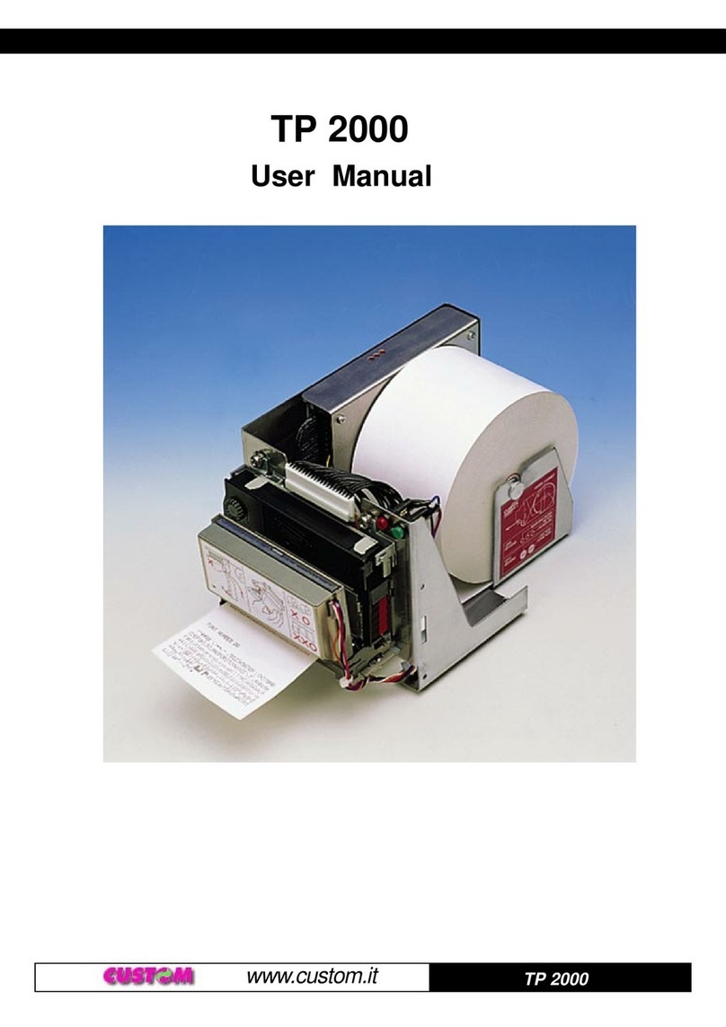
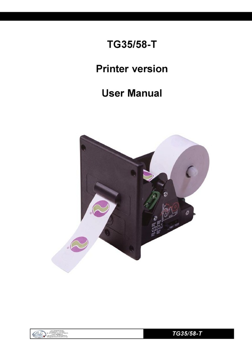
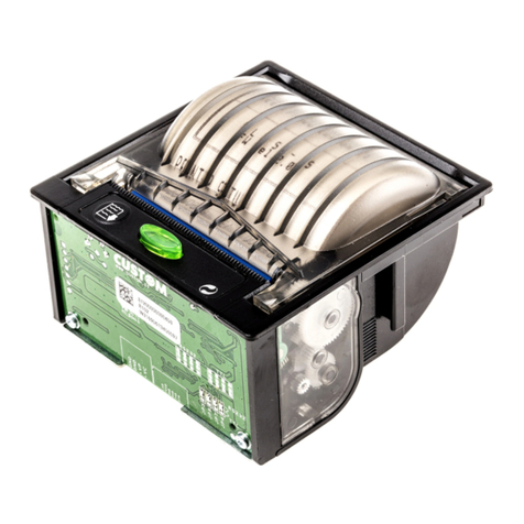
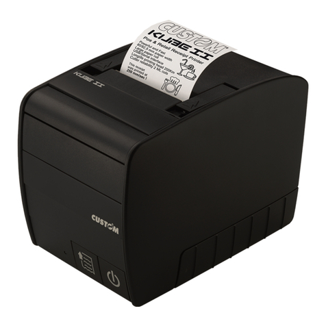
Custom Engineering TG1260 series User manual

TG1260/2460
TICKET PRINTER
TG1260 series
TG2460 series
60 mm
www.custom.it
User Manual

TG1260/2460
Allrightsreserved.Totalorevenpartialreproduction of this manual in any form, whether on paperorelectronically,
isstrictly forbidden. WhileCUSTOMENGINEERINGSPAguaranteesthat the informationcontainedinthismanual
hasbeen carefully checked andverified,CUSTOMENGINEERINGSPAandotherresourcesutilizedin itscreation
assume no responsibility for situations arising from its use.
Feedbackregarding any errors inthe manual’s content orsuggestions on how itcould be improved wouldbe
greatlyappreciated. Since its productsare subject tocontinuouschecking and improvement,CUSTOM
ENGINEERINGSPAreservestheright to modifytheinformation containedinthis manual withoutpriornotice.
COD. DOME - TG2460 VERS. 1.30
Copyright2004 CUSTOMENGINEERINGSPA– Italy
CUSTOMENGINEERINGSPA
Str.Berettine 2 - 43010Fontevivo(PARMA) - Italy
Phone:+390521-680111 - Fax : +39 0521-610701
http:www.custom.biz
To contact ourTechnical Support :

TG1260/2460
1
7
9
8
2345
6
10
PRINTERCOMPONENTS
Thefigures showed list printerparts with USBinterfacebut the remarksaregood for theRS232interface
printerstoo(apart from the connector).
A. TG1260/TG2460-x-A (1) External view
(1) The x suffix indicates the following models :
-TG1260/TG2460-U-A: USB interface, metal front panel and autocutter model.
-TG1260/TG2460-S-A: RS232 serial interface, metal front panel and autocutter model.
‘1-Printingmechanism
2-Autocutter
3- “Print” key
4-“Feed”key
5-Powersupply connector
6-USBinterface connector
7-Printerframe
8-Autocutter support plate
9-Paperoutput
10 - Status led

TG1260/2460
1
7
9
8
23
45
6
1
7
9
8
23
45
6
B. TG1260/TG2460-x-P (2) external view
(2) The x suffix indicates the following models :
- TG1260/TG2460-U-P: USB interface and plastic front panel.
- TG1260/TG2460-S-P: RS232 serial interface and plastic front panel.
1-Printingmechanism
2- “Print” key
3-“Feed”key
4-Powersupply connector
5-USBinterface connector
6-Printerframe
7- Plastic front panel
8-Paperoutput
9- Status Led
C. TG1260/TG2460-x-M (3) external view
(3) The x suffix indicates the following models :
- TG1260/TG2460-U-M: USB interface and metal front panel without autocutter model.
- TG1260/TG2460-S-M: RS232 serial interface and metal front panel without autocutter model.
1-Printingmechanism
2- “Print” key
3-“Feed”key
4-Powersupply connector
5-USBinterface connector
6-Printerframe
7-Metalfront panel
8-Paperoutput
9- Status Led

TG1260/2460
1
2
D. Back view (4)
(4) The back view is the same for all models available.
1-Paperinput
2-Inspectioncoverforpaperoutlet

TG1260/2460
Blankpage

TABLE OF CONTENTS
TG2460
i
INTRODUCTION
MANUALORGANIZATION ............................................................................................................................... 1
SYMBOLSUSEDIN THE MANUAL................................................................................................................. 1
GENERALSAFETYINFORMATION ................................................................................................................ 1
UNPACKINGTHEPRINTER ............................................................................................................................ 2
PRINTERDESCRIPTION ................................................................................................................................. 2
MAINAPPLICATIONS ...................................................................................................................................... 2
1.INSTALLATIONAND OPERATION
1.1CONNECTIONS ..................................................................................................................................... 1-1
1.1.1 Power supply TG1260 .................................................................................................................... 1-1
1.1.2 Power supply TG2460 .................................................................................................................... 1-1
1.1.3 USB connector ............................................................................................................................... 1-2
1.1.3 RS232 serial connector .................................................................................................................. 1-2
1.1.5 Connection printer-PC .................................................................................................................... 1-3
1.2 SETUP ................................................................................................................................................... 1-3
1.3AUTOTEST............................................................................................................................................. 1-4
1.4MAINTENANCE....................................................................................................................................... 1-5
1.4.1 Changing the paper roll ................................................................................................................... 1-5
1.4.2 Notes for installation and using the printer in the upside down position ........................................... 1-6
2. PRINTER FUNCTIONS
2.1CONTROLCHARACTERS ...................................................................................................................... 2-1
2.1.1ESC/POS Emulation ...................................................................................................................... 2-1
2.1.2CUSTOM Emulation ......................................................................................................................2-29
2.1.3 CBM iDP560RS Emulation............................................................................................................2-49
3.TECHNICALSPECIFICATIONS
3.1TECHNICALSPECIFICATIONS ............................................................................................................... 3-1
3.2DIMENSIONS.......................................................................................................................................... 3-3
3.2.1TG2460-U-A .................................................................................................................................... 3-3
3.2.2TG2460-U-N .................................................................................................................................... 3-3
3.2.3TG2460-U-M.................................................................................................................................... 3-4
4.CHARACTER SET
4.1CHARACTER SET .................................................................................................................................. 4-1
APPENDIXA -ACCESSORIES AND SPARE PARTS
A.1ACCESSORIES...................................................................................................................................... A-1
A.1.1 Power supply.................................................................................................................................. A-1
A.1.1.1 Power supply for TG2460 ............................................................................................................ A-1
A.1.1.2 Power supply for TG1260 ............................................................................................................ A-2
A.1.2Adjustablepaperholder supportkit ................................................................................................. A-3
A.1.3 Paper dispenser unit..................................................................................................................... A-12
A.2 SPARE PARTS..................................................................................................................................... A-13
TABLE OF CONTENTS
TG2460 ii
Blankpage

INTRODUCTION
TG2460
1
MANUALORGANIZATION
Inaddition to the Introductionwhich contains information regardingthesymbols used inthemanual, general
safetyinformation, instructions forunpacking the printer anda brief descriptionand main characteristics ofthe
machine,this manual isdividedinto the followingchapters:
Chapter1: Containstheinformation required for correct printerinstallationanduse
Chapter2: Containsadescription of printercontrols
Chapter3: Containsprintertechnical data
Chapter4: Contains the character sets (fonts) used by the printer
Appendix: Containsthe printer accessoriesandspare parts description
SYMBOLSUSED IN THE MANUAL
NOTE
Givesimportantinformation or suggestions for printeruse.
WARNING
Informationindicated by this symbolmustbe followed carefullytoavoid damaging the printer.
DANGER
Informationindicated by this symbolmustbe followed carefullytoavoid damage or operatorinjury.
GENERALSAFETYINFORMATIONS
•Readand retainthe instructions whichfollow.
•Before cleaning the printer, be sure to pull out the electrical cable.
•Use a damp cloth to clean the printer. Do not use liquid or spray products.
•Donotoperate the printer near water.
•When positioning the printer, make sure its cables will not be damaged.
•Use the type of electrical power supply indicated on the printer label. If uncertain, contact your dealer.
•Do not insert objects inside the printer as this could cause short-circuiting or damage components that
couldjeopardizeprinterfunctioning.
•Do not spill liquids onto the machine.
•Donot carry out repairson the machineyourself,except for thenormalmaintenance operations givenin
theuser manual.
•Unplugthe printer from the electricalmains and calla specialized repairmanif any ofthe following
conditionsshould arise:
A. thepower supply connector isdamaged
B. liquid has spilled into the printer
C. the printerhas been exposedto rain orwater
D. the printer is not functioning normally despite the fact that all instructions given in the user
manualhavebeenfollowed
E. theprinterhas been dropped andthecoveris damaged
F. printerperformanceisnoticeablyreduced
G. the printer is not working

INTRODUCTION
TG2460 2
1
2
3
4
5
6
UNPACKINGTHE PRINTER
Removethe printer fromthecarton, taking carenot to damage thepacking materials whichshouldbe retained
forfuture shipping/moving.
Make sure all components listed below are present and not damaged. If any part is missing and/or damaged,
contactcustomer service.
1. Box
2. Foam packing shell
3. Print
4. Paperroll
5. Manual(orCD-rom)
6. Electrical supply cable
PRINTERDESCRIPTION
Ultra compact thermal printer (only 9cm deep)
for dispensing 60 mm tickets width, easy to
install (4 fastening holes and ticket presentation
touser incorporated). Thanks to theexclusive
anti-paper-jam system, the ticket will always
be promptly dispensed to the user. Thanks to an
innovative type of paper roll holding bracket,
it is possible to accommodate up to 80 mm external
diameter paper rolls, adapt the printer to the mechanical
spacerequirements necessitatedby the application
(3positions: upper, lower andrear) and manage the
near paper end signal. It is equippedwitha 204 dpithermal
print mechanism; it has the serial RS232 interface and the
USBinterfaceand it’s also availableaversionequipped with
fireproofplastic ormetalfront panel, withor without autocutter.
• When the “PRINT” key is pressed during printer power up, it prints the graphic test.
• When the “FEED” key is pressed during printer power up, it prints the font test.
• When both the “PRINT” and the “FEED” keys are pressed during printer power up, it prints the SETUP report.
Pressing the “PRINT” key it’s possible to change the parameters value and to print the parameter current
value; pressing the “FEED” key it’s possible to pass to the next parameter till the end of the SETUP.
• The green Status LED displays a printer hardware error status and the winnings. The check is carried out“on
line”, i.e. in the event of a malfunctioning, the LED will starts flashing as follows:
DELSUTATSNOITPIRCSED
FFOsyawlAFFOretnirP
NOsyawlAstluafon–NOretnirP
)doirepgnolarofno(gnihsalfwolSdesiarrevocgnitliT
)doireptrohsarofno(gnihsalfwolSegasseMtuOrepaP
MAINAPPLICATIONS
This printer is the ideal solution for :
• kiosks (internet, public offices, bookings, bank transactions); • instant lotteries;
•self-service; • instruments;
• ticket dispensing (public/private transport, automatic payments); • gaming machines;
• parking lots; •vending machines;
• queue management systems.
(Fig. 1)

1. INSTALLATION AND OPERATION
TG1260/2460
11-
1.1 CONNECTIONS
1.1.1 Power supply (1260)
Everyprinter available is equippedwith a 2 pinmalemolex connector serie5569,for the powersupply.The
signals on the pins of the feed connector are as follows:
Model no. type : Header : 90°Molexserie5569(no.39-30-1020)
Housing: Molexserie5557(no.39-01-3022)
NIPLANGISNOITPIRCSED
1V42+REWOP
2DNGDNUORGLANGIS
WARNING:
Be sure to observe the correct polarity for the power supply.
1.1.2 Power supply (2460)
Every printer available is equipped with a 2 pin male molex connector serie 5569, for the power supply. The
signals on the pins of the feed connector are as follows:
Modelno. type : Header : 90°Molex serie 5569(no. 39-30-1020)
Housing: Molexserie 5557 (no. 39-01-3022)
NIPLANGISNOITPIRCSED
1
V21+REWOP
2DNGDNUORGLANGIS
WARNING:
Be sure to observe the correct polarity for the power supply.
(Fig.1.1)
(Tab.1.1)
(Tab.1.2)

1. INSTALLATION AND OPERATION
TG1260/2460 21-
1.1.3 USB connector
The printer with USB interface complies to USB 1.1 specifications that is:
• Communication speed equal to 12 Mbit/sec.
• Type of connector “Receptacle series B”.
The signals on the pins of the USB connector are as follows:
1.1.4 RS232 serial connector
The printer with serial RS232 interface is equipped with RJ45 connector. In the following table are described
the signals on the RS232 connector pins:
(Tab.1.3)
NIPLANGISNOITPIRCSED
1SUBV.C.N
2-D-ataD
3+D+ataD
4DNGlangisdnuorG
LLEHSDLEIHSgnidleihselbaC
(Fig.1.3)
(Fig.1.2)

1. INSTALLATION AND OPERATION
TG1260/2460
31-
NIPLANGISNOITPIRCSED
1.C.NdetcennoCtoN
2DNGlangisdnuorG
3DXTnoissimsnartataD
4DXRnoitpecerataD
5STRdnesotydaeR
6.C.NdetcennoCtoN
7.C.NdetcennoCtoN
8.C.NdetcennoCtoN
1.1.5 Connection Printer-PC
The diagrams below show a sample connection between printer and Personal Computer using a 8 pin male
RJ45 connector by printer side and a 9 pin female connector by a PC side.
Printer side PC side
1.2 SETUP
The printer enables the configuration of the printer default parameters (see fig. 1.4) pressing both the “PRINT”
andthe“FEED” keys during the printerpowerup.Theparameters affected during configurationare:
•Printer emulation: ESC/POSTM D, CUSTOM DPT24, CUSTOM DPT42 o CBM iDP560RS.
•Baud Rate: 115200, 57600, 38400, 19200D,9600, 4800,2400,1200.
•Data Lenght: 7, 8Dbits/chr.
•Parity:NoneD,even orodd.
•Handshaking:XON/XOFFDorHardware.
•Autofeed: CRdisabledDo CR enabled.
•USB Address(2):0D, 1, 2, 3, 4, 5, 6, 7, 8, 9.
•USB Monitor(2):DisabledD orenabled.
•Panel key: EnabledDor Disabled.
•Print mode: NormalDo Reverse.
•Font type:“ESC/POS“ emulation:
Chars / line:A=32 / B=42 col.Dor A=42 / B=56 col.
“DPT24” emulation:
Font type : FontADor Font B.
“DPT42” emulation:
Font type : FontADor Font B.
“CBM iDP560RS“ emulation:
Font dimensions: 11x24D40 col. or 18x24 24 col.
(Tab.1.4)
(Fig.1.4)

1. INSTALLATION AND OPERATION
TG1260/2460 41-
•Speed/Quality: NormalD, Low.
•Offline(1):DisabledD, Enabled.
•Print density: NormalD, Dark, Very Dark, Light, Very Light.
Notes: The parameters indicates with a Dsymbol are the default values.
(1) NOTE: Using this parameter, it is possible to select whether the Busy signal is activated
when the printer is both in Off Line status and the buffer is full, or only if the reception
buffer is full.
(2) NOTE: These parameters are shown only for the USB interface models.
The settings made are saved on the EEPROM (non volatile memory).
During the setup routine the printer prints out the setup report and will remain in standby until another key is
pressed or characters are received through the printer communication port.After this, each time the “PRINT”
key is pressed, the parameter is modified and its current value is printed. Once the required value has been
obtained, press the “FEED” key to proceed to the next parameter, and so on. Once all the parameters have
been run through, the printing of a message signals the end of the setting procedure.
1.3 AUTOTEST
To run the autotest, press the “FEED” key while switching on the printer. During the running of the autotest, the
character fonts and logos stored inside the printer are printed.
* PRINTER SETUP *
PROGRAM MEMORY..................OK
PRINTER BUFFER......................OK
CUTTER......................................OK
HEADVOLTAGE............[V] = 24,00
HEADTEMPERATURE[°C] = 32,5
PrinterEmul. :ESC/POS(TM)
BaudRate :9600bps
Datalength :8bits/chr
Parity :None
Handshaking :Xon/Xoff
Autofeed :CRdisabled
USBAddress :0
USBMonitor :Disabled
Panelkey :Enabled
PrintMode :Normal
Chars/ line :A=32/B=42col
Speed/Quality :Normal
Offline :Disabled
PrintDensity :Normal
[PRINT] key to enter setup
[FEED] key to skip setup
(Fig.1.5)

1. INSTALLATION AND OPERATION
TG1260/2460
51-
ab
1.4 MAINTENANCE
1.4.1 Changing the paper roll
Every time you change the paper, referred to fig.1.5, need to check as follows :
• Lift the wicket relative to paper roll compartment, and check that there are no scraps of paper at the area
indicated with a) letter near the printing head. If there are, remove the scraps before proceeding with any other
operation.
WARNING: Periodically remove accumulated paper dust from the drag paper roll and the area
around the paper outfeed sensor (see fig. 1.5 in the he points indicated with b letter).
(Fig.1.6)
(Fig.1.7)

1. INSTALLATION AND OPERATION
TG1260/2460 61-
Release the spring
from this side
To clean, do not use harsh chemical solvents; the use of a soft, alcohol-moistened
cloth is recommended.
To change the paper roll in the printer, proceed as follows:
1) Position the paper roll (1), so that it rotates in the direction shown in fig.1.6;
2) Insert the end of the paper roll in the print mechanism (2)andwait until the roll loadsautomatically;
3) Remove the ticket fromthe mouthpaper output;
WARNING
Before inserting the paper, ensure that it is cut evenly.
1.4.2 Notes for installation and using the printer in the upside down position
To install the printer in the upside down position proceed as follows :
(Fig.1.9)
(Fig.1.8)

1. INSTALLATION AND OPERATION
TG1260/2460
71-
Hook the spring
in this position
1) Release the spring as indicated in fig. 1.8 and placed it in the new position as indicated in fig. 1.9;
2) The printer is ready to be installed in the upside down position.
(3) NOTE: The operations described are valid for all models.
(Fig.1.11)
(Fig.1.10)

2. PRINTER FUNCTIONS
2-1 TG1260/2460
(Tab.2.1)
.moCXEH.moCIICSAnoitpircseD
80$SBretcarahcenofokcabgnivoM
90$THsbatlatnoziroH
A0$FLdeefenildnatnirP
D0$RCdeefenildn
atnirP
n40$01$nTOEELDnoissimsnartsutatsemit-laeR
81$NACatadtnirplecnaC
n02$B1$nPSCSEgnicapsedis-thgirretcarahc
teS
n12$B1$n!CSEedomtnirpteS
HnLn42$B1$HnLn$CSEnoitisopetulosbateS
kd...1dHnLnmA2$B1$kd...1dHnLnm*CSEedomegami
tibteS
nD2$B1$n-CSEffo/noedomenilrednunruT
03$B1$0CSEgnicapsenilhcni-8/1tceleS
23$B1$2CSEgnicapsenilhcni-6/1tc
eleS
n33$B1$n3CSEstinumuminimgnisugnicapsenilteS
n43$B1$n4CSEedomtpircsteser/teS
nD3$B1$n=CSEecivedtceleS
04$B1
$@CSEretnirpezilaitinI
00kn...1n44$B1$LUNkn...1nDCSEnoitisopbatlatnozirohteS
n54$B1$nECSEedomdlobtceleS
n74$B1
$nGCSEedomekirts-elbuodtceleS
nA4$B1$nJCSErepapdeefdnatnirP
n25$B1$nRCSEtesretcarahclanoitanretnitceleS
n65$B1
$nVCSE°09ybdetatoredomtnirpteS
HnLnC5$B1$HnLn\CSEnoitisoptnirpevitalerteS
n16$B1$naCSEnoitacifitsujtceleS
n53$
36$B1$n5cCSEsyeklenapelbasid/elbanE
n46$B1$ndCSEsenilnrepapdeefdnatnirP
96$B1$iCSEtuclatoT
n47$B1$ntCSEelbatedoc
retcarahctceleS
67$B1$vCSEsutatsretnirptimsnarT
87$B1$xCSEedomytilauq/deepstceleS
nB7$B1$n{CSEgnitnirpretcarah
cnwod-edispulecnac/teS
LyHyLxHxnAF$B1$LyHyLxHxn·CSEknabcihpargtnirP
HnLnFF$B1$HnLn}{CSEhsalfniyromemdnaogol
evieceR
43$0C$C1$4}{SFkcabgnivomrepapcitamotuadnatuclatoT
n12$D1$n!SGezisretcarahctceleS
A3$D1$:SGnoitinifedor
camfodne/gnitratsteS
2.1 CONTROL CHARACTERS
2.1.1 ESC/POS Emulation
The following table lists all the commands for the management of the ESC/POS™ Emulation. The commands
can be transmitted to the printer at any moment, but they will only be carried out when the commands
previously sent have been executed. There are no commands with priority status; all the commands are
carried out when the circular buffer is feed to do so.
COMMANDTABLE

2. PRINTER FUNCTIONS
2-2
TG1260/2460
.moCXEH.moCIICSAnoitpircseD
n24$D1$nBSGffo/nognitnirpesreverkcalb/etihwnruT
mn03$34$D1$mn0CSGedomtnirpretnuoc
tceleS
rnHbLbHaLa13$34$D1$rnHbLbHaLa1CSG)A(edomtnuoctceleS
HnLn23$34$D1$HnLn2CSGretnuoctceleS
B3$bsB3$asB3$3
4$D1$ B3$csB3$rsB3$ns ;rs;ns;bs;as;CSG ;cs )B(edomtnuoctceleS
n84$D1$nHSGsretcarahcIRHfonoitisopgnitnirptcel
eS
n94$D1$nISGDIretnirptimsnarT
HnLnC4$D1$HnLnLSGnigramtfelteS
yx05$D1$yxPSGstinunoitomlacitrevdnalatnozirohte
S
HnLn75$D1$HnLnWSGhtdiwaeragnitnirpteS
mtrE5$D1$mtr^SGorcametucexE
36$D1$cSGretnuoctnirP
n66$D1$nfSGsretcarahcIR
HroftnoftceleS
n86$D1$nhSGedocrabfothgiehtceleS
00mB6$D1$LUNmkSGedocrabtnirP
n27$D1$nrSGsutatstimsnarT
n77$D1$nw
SG edocrab)fo)noitacifingam(ezislatnozirohtceleS
nE7$D1$n~SGtpircsbus/tpircsrepusteS
nC7$D1$n|SGytisnedgnitn
irpteS
NOTE: in “Note” column where the model is not specified, the command is valid for all models.
The following pages provide a more detailed description of each command.
80$
[Name] Moving back of one character
[Format] ASCII BS
Hex 08
Decimal 8
[Description] Moves print position to previous character.
[Notes] This command can put two characters at the same position.
[Default]
[Reference]
[Example]
90$
[Name] Horizontal tabs
[Format] ASCII HT
Hex 09
Decimal 9
[Description] Moves the print position to the next horizontal tab position.
[Notes] • This command is ignored if the next horizontal tab position has not been set.
• If the next horizontal tab is outside the print area, the printer will print the entire
contents of the print buffer, then proceed with the processing of the horizontal tabs from
thebeginning of the followingline.
• The horizontal tabs are set through the command $1B $44.

2. PRINTER FUNCTIONS
2-3 TG1260/2460
[Default]
[Reference] $1B $44
[Example]
A0$
[Name] Print and line feed
[Format] ASCII LF
Hex 0A
Decimal 10
[Description] Prints the data in the buffer and feeds one line, based on the current line spacing.
[Notes] • This command sets the print position at the beginning of the line.
[Default]
[Reference] $1B $32, $1B $33
[Example]
D0$
[Name] Print and line feed
[Format] ASCII CR
Hex 0D
Decimal 13
[Description] When autofeed is $0D enabled, this command functions in the same way as $0A,
otherwise it is ignored.
[Notes] • This command sets the print position at the beginning of the line.
[Default] See autofeed parameter on Setup.
[Reference] $0A
[Example]
n40$01$
[Name] Transmission of status in real time
[Format] ASCII DLE EOT n
Hex 10 04 n
Decimal 16 4 n
[Range] 1 ≤n ≤4, n =17, 20 ≤n ≤21
[Description] Transmits in real time the selected status of the printer specified by naccording to the
following parameters:
n = 1 transmit printer status
n = 2 transmit off-line status
n = 3 transmit error status
n = 4 transmit paper roll sensor status
n = 17 transmit paper status
n = 20 transmit Full Status
n = 21 transmit printer ID ($6D )
[Notes] • This command is executed even when the reception buffer is full.
The status is transmitted whenever the data sequence $10 $04 n is received.
[Default]
[Reference]
[Example] n=1: Printer status
This manual suits for next models
1
Table of contents
Other Custom Engineering Printer manuals

Custom Engineering
Custom Engineering TG02H User manual

Custom Engineering
Custom Engineering TG35/58-T User manual

Custom Engineering
Custom Engineering s'print User manual

Custom Engineering
Custom Engineering MT002-1 User manual

Custom Engineering
Custom Engineering Ticket Gaming TG35 User manual

Custom Engineering
Custom Engineering KPM150-H User manual

Custom Engineering
Custom Engineering KUBE II ETH User manual

Custom Engineering
Custom Engineering KPM 216H II User manual

Custom Engineering
Custom Engineering s'print User manual

Custom Engineering
Custom Engineering My3-BT3B User manual