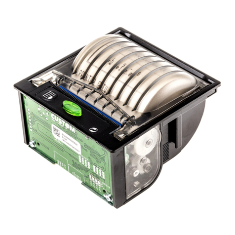
Custom Engineering TP 2000 User manual

TP 2000
TP 2000
User Manual
www.custom.it

TP 2000
2
All rights reserved. The reproduction of this manual, either totally or partially, in any
form whatsoever, whether it be on paper or through computer processes, is strictly
prohibited. Custom Engineering s.r.l. and the resource teams employed in the making
of this manual will not be held responsible for any problems arising as a result of
improper use of this manual, as they guarantee that the information contained in it has
been subjected to careful inspection.
Any suggestions regarding errors in its contents or possible improvements will,
nonetheless, be greatly appreciated. The products are continuously checked and
improved. For this reason Custom Engineering s.r.l. reserves the right to modify the
information contained in this manual without prior notice.
COD. DOME-TP2000 Revision 1.10
Copyright 1998 Custom Engineering s.r.l. – Italy
Custom Engineering
Str. Berettine 2 - 43010 Fontevivo (PARMA) - Italy
Tel. : +39 0521-680111 - Fax : +39 0521-610701

TP 2000
3
ytimrofnoCfonoitaralceD"EC"ytimrofnoCfonoitaralceD"EC" ytimrofnoCfonoitaralceD"EC" ytimrofnoCfonoitaralceD"EC"ytimrofnoCfonoitaralceD"EC"
41054NEdna22ediuGCEI/OSIsdradnatshtiwecnadroccanI41054NEdna22ediuGCEI/OSIsdradnatshtiwecnadroccanI 41054NEdna22ediuGCEI/OSIsdradnatshtiwecnadroccanI 41054NEdna22ediuGCEI/OSIsdradnatshtiwecnadroccanI41054NEdna22ediuGCEI/OSIsdradnatshtiwecnadroccanI :°N 6910110CD
:emans'rerutcafunaM.l.r.sgnireenignEmotsuC
:sserddas'rerutcafunaM2enittereBadartS )amraP(ovivetnoF ylatI
:tcudorpehttahtseralceD
:emantcudorPresnepsidtpiecertekciT
:epyttcudorP0002PT
:ledoM0002PT
:sevitceridgniwollofehthtiwytimrofnocnisi
EEC/86/39;EEC/13/29;EEC/633/98evitceriDytilibitapmoCcitengamortcelE
:sdradnatsgniwollofehthtiwecnadroccanI
22055NE BssalC ehtgnirusaemfosdohtemdnastimiL ybdecudorpecnabrutsidoidarfoscitsiretcarahc tnempiuqeygolonhcetnoitamrofni
4991
1-28005NEytinummilareneG-ytilibitapmoccitengamortcelE laicremmoc,laitnediseR:1traP.stnemeriuqer .stnemnorivneyrtsudnithgildna
2991
2-4-00016NE.stsetytinummiegrahcsidcitatsortcelE egrahcsidriaVK8,egrahcsidtcatnocVK4 5991
4-4-00016NE.stsetytinummitsrub/tneisnarttsaflacirtcelE VK1CAsenilrewoPVK5.0senillangiS 5991
04105VNEsdleifcitengamortceledetaidarriycneuqerf-oidaR .tsetytinummI- MAzHK1%08,zHM0001-zHM08,m/V3
3991
6991yraunaJ

TP 2000
4
GENERAL INFORMATION REGARDING SAFETY
•Read and keep the following instructions.
•Observe all warnings and follow all instructions attached to the printer.
•Before cleaning the printer, disconnect the feed cable.
•Clean the printer with a damp cloth. Do not use liquid or spray products.
•Do not operate the printer near to water.
•Do not place the printer on unsteady surfaces. It could fall and get seriously
damaged.
•Use the type of electricity supply marked on the printer label. In the event of
uncertainty, contact the seller.
•Position the printer in such a way as to ensure that the cables connected to it will
not be damaged.
•Ensure that the maximum absorbed current of the printer does not exceed the
maximum acceptable current for the type of feed cable used.
•Do not put objects of any kind inside the printer as they could cause a short circuit
or damage parts which could affect its performance.
•Do not spill liquids on the printer.
•Do not carry out technical operations on the printer with the exception of the
scheduled maintenance operations specifically indicated in the user’s manual.
•Disconnect the printer from the electricity supply and have it repaired by a
specialized technician should any of the following conditions occur:
A. The feed connector has been damaged.
B. Liquid has penetrated to the inside of the printer;
C. The printer has been exposed to rain or water;
D. The printer is not operating normally despite the instructions in the user’s
manual having been followed.
E. The printer has been dropped and its case damaged.
F. The performance of the printer is poor.
G. The printer does not work.
TP 2000
5
GENERAL SPECIFICATIONS
Power supply +12 VDC
Current
Medium 2A
Peak 4A
Serial interface RS232withDB9connector
Parallel interface Centronics(DB25)
Print mode text 35and42columnwith6x10matrix
17and21columnindoublewidthmode
Image 210dots/line
Environmental conditions
Operatingtemperature 0°C - +50°C
Operatinghumidity 35% - 85%
Storagetemperature/humidity -20°C - +70°C / 10%-90%
•Itispossibletoprintinimageandtextmodesimultaneouslywithupto14 software-selectable fonts
available.
• Bidirectional printing
• Self Check
•Emergencystop
•Automatic printingwithfull line buffer
•Printcolorselection
DESCRIPTION

TP 2000
6
J1 CUTTER CONNECTOR
No. SIGNAL
1 Cutterposition sensors
2 Cutter position sensors
3 GND
4 Cutter Motor 1 Control
5 Cutter Motor 2 Control
J4 POWER SUPPLY CONNECTOR
No. SIGNAL
1 +12 – 14 VDC
2 GND
J5 RS232 SERIAL CONNECTOR
No. SIGNAL FUNCTION
1
2 TX RS-232 Data output
3 RX RS-232 Data input
4
5 GND GND
6 DSR Printer ON Indicator (+12 V active)
7
8 RTS Request to send
9
CONNECTORS LIST

TP 2000
7
J10 STEP MOTOR CONNECTOR
No. SIGNAL
1 +12VDC Motor Neutral Wire
2 +12VDC Motor Neutral Wire
3 Phase 1
4 Phase 2
5 Phase 3
6 Phase 4
7 +5VDC
8 GND
9 Paper Signal (see J8)
10 Power on LED
11 n.c.
12 n.c.
13 +5 VDC
14 GND
15 Notch Signal (see J7)
16 Power on LED
This connector is EPSON M260-C-compatible, but it may also be used with other types of step motors.
The photocell signals are on the connector.
J2 PRINTER CONNECTOR
No. FUNCTION
1 Trigger magnet -
2 Trigger magnet +
3 Reset detector
4 GND
5 GND
6 Solenoid A
7 Solenoid B
8 Solenoid C
9 +12 VDC
10 +12 VDC
11 +12 VDC
12 Solenoid D
13 Solenoid E
14 Solenoid F
15 Solenoid G
16 +12 VDC Motor
17 Timing detect
18 Timing detect
19 Motor
20 n.c.
CONNECTORS LIST

TP 2000
8
J6 KEYBOARD CONNECTOR
No. SIGNAL FUNCTION
1 VDC present LED Output that activates the LED signalling 5VDC present.
2 Form Feed Key Key normally open, when pressed during normal operation, advances
thepaper up to a given signal (see J7).Iftheprinterdoes not encounter
the signal, after a maximum number of lines, the paper feed stops
automatically. This value is entered from the software.
During programming, this key is used to confirm entry selection.
3 Line Feed Key Key normally open, when pressed during normal operation,causes the
paper to advance for as long as it is held down. If pressed during reset,
the printer enters set-up. During set-up it is used to select the various
options. (see PROGRAMMING)
4 On-Line LED On-Line LED signal output. Remains lit during normal operation, but is
off during test and set-up and when OFF-LINE.
5 On-Line Key Key normally open, if pressed during reset, the printer will enter self-
check mode. During normal operation, it is used to switch between
ON-LINEand OFF-LINE.WhenOFF-LINE, the LEDgoesoff,theprinter
registers busy and suspends printing of any job currently in progress.
6 GND
CONNECTORS LIST

TP 2000
9
J3 CENTRONICS PARALLEL CONNECTOR
No. SIGNAL FUNCTION
1 STROBE A low-level impulse indicates that the dataisreadytoberead.
2 D0 Data 0
3 D1 Data 1
4 D2 Data 2
5 D3 Data 3
6 D4 Data 4
7 D5 Data 5
8 D6 Data 6
9 D7 Data 7
10 ACK A low-level impulse indicates that the printer has received the data.
11 BUSY A high-level signal indicates that the printer cannot receive data.
12 PE Paper End
13 SELECT Always high, or alternately indicates the presence of paper under the
NOTCH photocell (see JP3).
14 n.u.
15 ERROR A low level indicates error status.
16 INIT A low-level impulse causes the printer to reset.
17 GND
18 GND
19 GND
20 GND
21 GND
22 GND
23 GND
24 GND
25 GND
J9 REWINDER CONNECTOR
No. SIGNAL FUNCTION
1 +12VDC MOTOR This connector is used to supply power to a paper winder.
POWER SUPPLY Voltage is present on pin 1 when the printer is ON.
2 GND
CONNECTORS LIST

TP 2000
10
J7 NOTCH SENSOR CONNECTOR
No. SIGNAL FUNCTION
1 LED POWER SUPPLY Outputfor supplyingpowerto thephotocellLED.
2 NOTCH SIGNAL This signal serves to register either the presence of a notch
during FORM FEED or the position of the paper or receipt
when being used as a dispenser.
Paper presence signal 0=paper present 1= no paper
3 GND
4 GND
J8 PAPER SENSOR CONNECTOR
No. SIGNAL FUNCTION
1 LED POWER SUPPLY Output for supplying power to the photocell LED.
2 PAPER SIGNAL This signal serves to register either paper presence during
printing or the position of the paper or receipt when being
used as a dispenser.
Paper presence signal 0=paper present 1= no paper
Instead of a photocell, a microswitch may be used which,
when paper is present closes pin 2 at ground.
If neither a photocell nor a microswitch is desired, place a
jumper between pins 2 and 3.
!!!!!!!! If no jumper or paper sensor are present, the
MACHINE WILL NOT PRINT !!!!
3 GND
4 GND
CONNECTORS LIST

TP 2000
11
EMERGENCY STOP
If any one of the following problems arises during printer functioning, power is cut off to the motor,
solenoidsand triggermagnetand the ERRORsignalis at LOWlevel.Simultaneously, the BUSYandRTS
signalsindicate that the printer is in use. Reset the printer toresumeoperation.
1) Motor frozen
2) Timing detector timeout
3) Reset detector timeout
SELF-CHECK - AUTOTEST
If the FORM FEED key is held down during power-up, the printer will carry out a self-check routine in
which all font character sets will be printed out in continuous mode. To exit this routine, press the FORM
FEED key a second time.
PROGRAMMING OPERATING PARAMETERS
To enter this routine, hold the LINE FEED key down during power-up. The machine will begin to print out
all available fonts numbered 00 to 0x, a graphics test and, at the end, a machine status report.
Example: PRINT DIRECTION NORMAL
PRINT MODE NORMAL
PARALLEL PORT
AUTOFEED OFF
SELECTED FONT No.00
with the following messages:
PRESS LINE FEED TO ENTER SET-UP
PRESS FORM FEED TO SKIP SET-UP
When FORM FEED is pressed, the machine exits the set-up routine and automatically resets to zero; if
LINE FEED is pressed, the machine enters the set-up routine.
At this point, the LINE FEED key functions as a cursor for selecting the various functions and the FORM
FEED key is used to confirm the parameters selected.
USE

TP 2000
12
Table’s parameters setting
PRINT DIRECTION NORMAL
REVERSE
PRINT MODE NORMAL
DOUBLEWIDTH
DOUBLE HEIGHT
EXPANDED
PARALLEL PORT
SERIAL PORT RATE 9600
4800
2400
1200
600
300
PARITY NONE, BIT 8, STOP 1
PARITY NONE, BIT 8, STOP 2
PARITY NONE, BIT 7, STOP 2
PARITY EVEN, BIT 8, STOP 1
PARITY ODD, BIT 8, STOP 1
PARITY EVEN, BIT 7, STOP 1
PARITY ODD, BIT 7, STOP 1
PARITY EVEN, BIT 7, STOP 2
PARITY ODD, BIT 7, STOP 2
PROTOCOL XON/XOFF
RTS
AUTOFEED OFF
ON
Whenprogramming has been completed,themachineprints out a report withthenewset-up parameters
and automatically resets.
USE

TP 2000
13
Control commands list
ASCII CR
Hex 0Dh
Description Carriage Return
If AUTOFEED is ON, functions like the LF command; if OFF this command is ignored.
ASCII LF
Hex 0Ah
Description Line Feed
When this command is received, all data in the line buffer is printed out. If the buffer is
empty, the paper is fed one line.
ASCII ESC d
Hex 1Bh + 64h + n
Description Feed paper n lines
When this command is received, < n > line feeds are carried out.
N.B.: This command does not print out the line buffer.
ASCII ESC !
Hex 1Bh + 21h + n
Description Select print mode
Thiscommandselectstheprintmode.Dependingonthestatusofthe<n>bits,itactivates
or deactivates the double height, double width or underline options, where n1 :
bit 0 = 1 = double width
bit 1 = 1 = double height
bit 2
bit 3
bit 4
bit 5
bit 6
bit 7 = 1 = underline
ASCII ESC R
Hex 1Bh + 52h + n
Description Selects font to be used
Selects one of the available fonts. This number is displayed during the start-up test.
If <n> is greater than this number it is ignored.
This command permits the use of all available fonts during a single work session, but
the printer will return to the default font following initialization.
COMMANDS

TP 2000
14
ASCII ESC @
Hex 1Bh + 40h
Description Reinitializes the printer
When this command is received, the printer resets and all default parameters are
restored. Equivalentto turningthemachine offandthen onagain.
ASCII ESC *
Hex 1Bh + 2Ah + m + n1 + n2 + data
Description Prints in image mode
Prints a line in image mode. After this command has been received, the machine waits
for the reception of (n2*256)+n1 bytes. The maximum number of dots per line is 210.
A line printed in image mode is 8 dots high. Parameter <m> is a byte included for
eventual future expansion which is not used and can therefore have any value.
Example:
To print a solid line 8 dots high and 210 dots long
<1Bh> <2Ah> <00h> <D2h> <00h> (210 * <FFh>)
ASCII ESC K
Hex 1Bh + 4Bh + n1 + n2 + n3 + n4 + n5 + data
Description Prints a graphic image
This command allows for the printing in image mode of a graphic ((n4*256)+ n3) wide,
n5 lineshigh and with a border offset of ((n2*256)+n1) dots. The number of dots per
line is 210 and anything over this amount is read but not displayed. Therefore, it is
important to make sure that the margin offset plus line length does not exceed the
maximum allowed.
Example:
To print a square 80*80 dots, 100 dots from the border
<1Bh> <4Bh> <00h><64h> <00h><50h> <0Ah> (800 * <FFh>)
dots offset 80 dots 80/8 data bytes length height (len * ht)/8
ASCII ESC r
Hex 1Bh + 72h + n
Description Sets print color ( only in the two-color model )
When this command is received, the ribbon color changes.
The color is determined by n: n = 0Black
n = 1Red
COMMANDS

TP 2000
15
COMMANDS
ASCII ESC i
Hex 1Bh + 69h
Description Complete cut
Ifthe cutter is not disactivated, a complete paper cutiscarriedout.Ifthe cutter is not
connected, the disactivation flag is set and any subsequent paper cut commands will
be ignored.
ASCII ESC m
Hex 1Bh + 6Dh
Description Partial cut
If the cutter is not disactivated, a partial paper cut is carried out. If the cutter is not
connected, the disactivation flag is set and any subsequent paper cut commands will
be ignored.
ASCII ESC &
Hex 1Bh + 26h + n1 + n2 + ... n11
Description Defines a new character
This command is used to change a font character and is useful for personalizing fonts.
The modification is only temporary, and changes made to the character are cancelled
when the printer is reset or the font is changed using the ESC+ t o ESC R commands.
n1 = value of the byte to be modified (32÷255)
n2÷n11 = 10 bytes that make up the 10 rows of the character
Example:
To change the letter “A” so that it has double-width lines and is taller
1Bh + 26h + 41h + 1Eh + 3Fh + 33h + 33h + 3Fh + 3Fh + 33h + 33h + 33h + 33h

TP 2000
16
ASCII ESC W
Hex 1Bh + 57h + n
Description Sets the number of columns
Thiscommand selects the number of print columns. Itmustbechangedat the beginning
of a line since it is not possible to print a line in two different modes, and it also causes
theline buffer tobecancelled. The numberofcolumns is determinedby<n>:
n = 035 columns
n = 142 columns
ASCII ESC t
Hex 1Bh + 74h + n
Description Selects the default font
Selects the new font to be used which automatically becomes the default font. This
means that following the next initialization, the font used will be the one that has just
been selected. The font number must be chosen from among the available ones, and
any request for n1 greater than the fonts available will be ignored. The font number is
displayed during set-up.
ASCII ESC C
Hex 1Bh + 43h + n
Description Selects print direction
This command selects print direction, i.e., in which direction the line is printed.
n1 == 0 normal printing
n1 <> 0 reverse printing
ASCII ESC l
Hex 1Bh + 6C + n
Description Setting cutter status
This command selects cutter status, activating or disactivating it depending on the
status of <n>. If disactivated, <Esc i> and <ESC m> are ignored.
Ifthecutter isactivated butfor somereason isinactive (breakdown,connector unplugged,
etc.) the flag is reset. Cutter presence is tested duringpower-upand if itisnotpresent,
it is disactivated automatically.
n1 == 0 cutter disactivated
n1 <> 0 cutter activated
COMMANDS

TP 2000
17
ASCII ESC f
Hex 1Bh + 66h + n
Description Status request
Thiscommand requests a stamper statusreport.
The response byte is sent via the serial port without any control
bit 0 = PAPER
bit 1 = NOTCH
bit 2 = F-FEED
bit 3 = L-FEED
bit 4 = ERROR
bit 5 = CUTTER PRESENT
bit 6 =
bit 7 = MOTOR STATUS
ASCII ESC A
Hex 1Bh + 41h + n1 + n2
Description Moves the step motor
This command moves the step motor in direction n1, n2 lines
n1 == 0 forward
n1 <> 0 backward
n2 = number of steps
ASCII ESC z
Hex 1Bh + 7Ah + n
Description Sets the number of lines for Form Feed
This command sets the maximum number of lines for the Form Feed.
COMMANDS
Table of contents
Other Custom Engineering Printer manuals

Custom Engineering
Custom Engineering Ticket Gaming TG35 User manual

Custom Engineering
Custom Engineering KPM150-H User manual

Custom Engineering
Custom Engineering KPM150-H User manual

Custom Engineering
Custom Engineering s'print User manual

Custom Engineering
Custom Engineering s'print User manual

Custom Engineering
Custom Engineering MT002-1 User manual

Custom Engineering
Custom Engineering My3-BT3B User manual

Custom Engineering
Custom Engineering PLUS II User manual

Custom Engineering
Custom Engineering VKP80II User manual

Custom Engineering
Custom Engineering TG35/58-T User manual