Custom Engineering PLUS II User manual

OEM
USER MANUAL
PLUS II
PLUS II
Command Reference: DOMC-0009e

All rights reserved. Total or partial reproduction of this manual in whatever form, whether by printed or elec-
tronic means, is forbidden. While guaranteeing that the information contained in it has been carefully checked,
CUSTOM ENGINEERING SPA and other entities utilized in the realization of this manual bear no responsibility
for how the manual is used.
Information regarding any errors found in it or suggestions on how it could be improved are appreciated. Since
products are subject to continuous check and improvement, CUSTOM ENGINEERING SPA reserves the right
to make changes in information contained in this manual without prior notification.
Copyright © 2007 CUSTOM ENGINEERING S.p.a. – Italy
CUSTOM ENGINEERING S.p.A.
Str. Berettine 2 - 43010 Fontevivo (PARMA) - Italy
Tel.: +39 0521-680111 - Fax: +39 0521-610701
http: www.custom.biz
Customer Service Department:
Tel.: +39 059 88 69 587
Email: [email protected]

PRINTER COMPONENTS
A. PLUS II - Front view
1 - STATUS Led
2 - Paper roll compartment
3 - Paper mouth
4 - OPEN key
5 - FEED key
5
4
3
1
2
1
2
PLUS II
4
1
2
5
3
1
2
1
2
PLUS II (OPTION -0128)
(Fig.1)
(Fig.2)
User Manual PLUS II

B. PLUS II - Rear view
1 - Power supply connector
2 - RS232 / TTL serial interface connector
3 - CENTRONICS / TTL parallel interface connector
4 - USB interface connector
5 - RS232 serial interface connector (1)
1 2 1 2
PLUS II-S / PLUS II-T PLUS II-S-0004
1 3 1 3
PLUS II-C / PLUS II-P PLUS II-C-0004
(Fig.3) (Fig.4)
(Fig.5) (Fig.6)
PLUS II User Manual

145
PLUS II-USB
NOTE (1) : RESERVED interface, only for service use.
(Fig.7)
User Manual PLUS II

C. PLUS II - Internal view
1 - Printing head
2 - Rubbed roller
3 - Seat for fixing hook (provided in the package)
4 - Paper presence sensor
5 - Cover open sensor (optional)
4
5
3
1
2
NOTE : The description of the internal components is valid for all the PLUS II models.
(Fig.8)
PLUS II User Manual

INTRODUCTION
MANUAL CONTENTS......................................................................................................................................1
EXPLANATORY NOTES USED IN THIS MANUAL .........................................................................................1
GENERAL SAFETY INFORMATION................................................................................................................ 1
UNPACKING THE PRINTER ...........................................................................................................................2
GENERAL FEATURES.....................................................................................................................................3
1. INSTALLATION AND USE
PRINTER DESCRIPTION ................................................................................................................................ 3
1.1 PAPER SPECIFICATIONS......................................................................................................................1-1
1.1.1 Specifications for LINERLESS paper ..............................................................................................1-1
1.2 CONNECTIONS OF PLUS II-S AND PLUS II-T......................................................................................1-2
1.2.1 Power supply...................................................................................................................................1-2
1.2.2 Setting serial interface.....................................................................................................................1-3
1.3 CONNECTIONS OF PLUS II-S-0004......................................................................................................1-4
1.3.1 Power supply...................................................................................................................................1-4
1.3.2 Setting serial interface.....................................................................................................................1-5
1.3.3 Power-On configuration...................................................................................................................1-5
1.4 CONNECTIONS OF PLUS II-C AND PLUS II-P .....................................................................................1-6
1.4.1 Power supply...................................................................................................................................1-6
1.4.2 Setting serial interface.....................................................................................................................1-7
1.5 CONNECTIONS OF PLUS II-C-0004......................................................................................................1-8
1.5.1 Power supply...................................................................................................................................1-8
1.5.2 Setting serial interface.....................................................................................................................1-9
1.5.3 Power-On configuration...................................................................................................................1-9
1.6 CONNECTIONS OF PLUS II-USB........................................................................................................1-10
1.6.1 Power supply.................................................................................................................................1-10
1.7 SELF-TEST ........................................................................................................................................... 1-11
1.8 CONFIGURATION.................................................................................................................................1-12
1.9 HEXADECIMAL DUMP .........................................................................................................................1-13
1.10 MAINTENANCE ..................................................................................................................................1-13
1.10.1 Changing the paper roll ...............................................................................................................1-13
1.10.2 Notes about the installation .........................................................................................................1-15
1.10.3 “EASYLOCK” fixing system.........................................................................................................1-16
TABLE OF CONTENTS
User Manual PLUS II i

2. INTERFACES
2.1 INTERFACE OF PLUS II-S AND PLUS II-T ............................................................................................2-1
2.1.1 Connection Printer-PC ....................................................................................................................2-2
2.2 INTERFACE OF PLUS II-S-0004 ............................................................................................................2-4
2.2.1 Connection Printer-PC ....................................................................................................................2-5
2.3 INTERFACE OF PLUS II-C AND PLUS II-P............................................................................................2-6
2.3.1 Connection Printer-PC ....................................................................................................................2-7
2.4 INTERFACES OF PLUSII-C-0004...........................................................................................................2-9
2.4.1 Connection Printer-PC ..................................................................................................................2-10
2.5 INTERFACES OF PLUS II-USB............................................................................................................ 2-11
2.5.1 USB interface ................................................................................................................................ 2-11
2.5.1 RS232 serial interface ...................................................................................................................2-12
3. TECHNICAL SPECIFICATIONS
3.1 TECHNICAL SPECIFICATIONS..............................................................................................................3-1
3.2 DIMENSIONS..........................................................................................................................................3-4
4. CHARACTER SETS
4.1 CHARACTER SETS................................................................................................................................4-1
4.1.2 Character sets for PLUS II-S, PLUS II-S, PLUS II-T, PLUS II-C, PLUS II-T ...................................4-1
4.1.2 Character sets for PLUS II-USB......................................................................................................4-2
APPENDIX A - ACCESSORIES AND SPARE PARTS
A.1 ACCESSORIES ..................................................................................................................................... A-1
A.1.1 Power supply ................................................................................................................................. A-1
A.1.2 Adaptor frame kit 112X112 ............................................................................................................. A-3
A.1.3 Data and power supply cables kit for PLUS II-S and PLUS II-T .................................................... A-6
A.1.4 Data serial cable kit for PLUS II-S-0004 ........................................................................................ A-7
A.1.5 Data and power supply cables kit for PLUS II-C and PLUS II-P.................................................... A-8
A.1.6 Data parallel cable kit for PLUS II-C-0004 ..................................................................................... A-9
A.2 SPARE PARTS..................................................................................................................................... A-10
A.2.1 Supplies ....................................................................................................................................... A-10
TABLE OF CONTENTS
ii PLUS II User Manual

MANUAL CONTENTS
In addition to the Introduction which includes a description of the explanatory notes used in the manual, general
safety information, how to unpack the printer and a brief description of the printer including its basic features,
this manual is organized as follows:
Chapter 1: Contains the information required for correct printer installation and its proper use
Chapter 2: Contains information on interface specifications
Chapter 3: Contains technical specifications of the printer
Chapter 4: Contains the character sets (fonts) used by the printer
EXPLANATORY NOTES USED IN THIS MANUAL
N.B.
Gives important information or suggestions relative to the use of the printer.
WARNING
Information marked with this symbol must be carefully followed to guard against damaging the
printer.
DANGER
Information marked with this symbol must be carefully followed to guard against operator injury
or damage.
GENERAL SAFETY INFORMATION
• Read and keep the instructions which follow.
• Follow all warnings and instructions indicated on the printer.
• Before cleaning the printer, disconnect the power supply.
• Clean the printer with a damp cloth. Do not use liquid or spray products.
• Do not operate the printer near water.
• Do not use the printer on unstable surfaces that might cause it to fall and be seriously damaged.
• During the integration of the printer, we strongly warn to keep an adeguate paper loop outlet underneath
the presenter, in order to allow the receipt being properly printed out.
• Only use the printer on hard surfaces and in environments that guarantee proper ventilation.
• Make sure the printer is placed in such a way as to avoid damage to its wiring.
• Use the type of electrical power supply indicated on the printer label. If in doubt, contact your retailer.
• Do not block the ventilation openings.
• Do not introduce foreign objects of any kind into the printer as this could cause a short circuit or damage
parts that could jeopardize printer functioning.
• Do not spill liquids onto the printer.
• Do not carry out technical operations on the printer, with the exception of the scheduled maintenance
procedures specifically indicated in the user manual.
• Disconnect the printer from the electricity supply and have it repaired by a specialized technician when:
A. The feed connector has been damaged.
B. Liquid has seeped inside the printer.
C. The printer has been exposed to rain or water.
D. The printer is not functioning normally despite the fact that all instructions in the users
manual have been followed.
E. The printer has been dropped and its outer casing damaged.
F. Printer performance is poor.
G. The printer is not functioning.
INTRODUCTION
User Manual PLUS II 1


UNPACKING THE PRINTER
Remove the printer from its carton being careful not to damage the packing material so that it may be re-used
if the printer is to be transported in the future. Make sure that all the components illustrated below are present
and that there are no signs of damage. If there are, contact Customer Service.
1. Fixing hooks
2. Box
3. Paper roll (inside the printer)
4. Printer
4
3
1
1
2
Open the printer packaging•
Take out the fixing hooks and remove it from its plastic covering•
Take out the printer and remove it from its plastic covering•
Keep the box packing materials in the event the printer must be transported/shipped in the future•
(Fig.1)
INTRODUCTION
2 PLUS II User Manual

GENERAL FEATURES
PLUS II is the new ultra-compact thermal panel printer, paper width 57,5 mm, with “SIXLOAD” easy paper loading
system. PLUS II is performing and versatile, able to satisfy any printing requirements for industrial automation
and garage equipment. In particular, PLUS II is suitable for measurement instrument applications, analysis and
check, weighing systems, gas analyser, anti-theft devices, autoclaves, Pos.
PLUS II is provided with the innovative fixing system “EASYLOCK”: this system allows to fit the printer to any
panel thickness. Moreover PLUS II can be equipped with a plastic surround which makes mechanically com-
patible with CUSTOM F and P series panel printers.
PLUS II is available with serial RS232/TTL interface, parallel Centronics/TTL, USB and paper sensor. It’s
equipped with a 204 dpi thermal printing mechanism, using 57,5 mm-wide paper rolls. It can print 24, 32, 40 or
42 characters per line according to the printer’s model and to the selection made at the Setup stage or through
a software command. Printer manage LINERLESS paper.
PRINTER DESCRIPTION
The printer has an ABS casing with a front cover which opens to allow access to the paper roll and print head.
The control panel is located on the front (see fig.2) and has a FEED key (3) and an OPEN key (1) for paper
roll compartment opening. The OPEN key is made of transparent plastic material so it works also a STATUS
Led (2).
In the PLUS II model with the OPTION -0128, the OPEN key is not present because the front panel is opened
by the two plastic hooks (see fig.3).
1 2 3 2 3
PLUS II PLUS II (OPTION -0128)
(Fig.2) (Fig.3)
INTRODUCTION
User Manual PLUS II 3

• FEED key When the LINE FEED key is pressed (see fig.4), the printer advances the paper. During
power-up, if the FEED key is held down, the printer enters the SETUP routine and print the
SETUP report. The printer will remain in standby in Hexadecimal dump mode until another
key is pressed or characters are received through the printer communication port; for every
10 characters received it prints hexadecimal values and ASCII codes (if the characters appear
underlined, it means the receive buffer is full); See Hexadecimal Dump.
• OPEN key Press the OPEN key to open the paper roll compartment.
< 500 msec
FAST PUSH > 500 msec
PUSH
FEED
The FEED key functions are valid for all the PLUS II models.
ENTER SETUP
PRINT SETUP REPORT
Next parameter
SKIP SETUP
ON
Modify parameter
(Fig.4)
INTRODUCTION
4 PLUS II User Manual

• STATUS led displays printer hardware status. In case of malfunction, the flash frequency changes as shown
in Tab.1 for models with USB interface and in Tab.2 for all the other models.
STATUS
LED COLOUR DESCRIPTION
OFF Printer OFF
GREEN Printer ON: no error
GREEN
COMMUNICATION STATUS
Nr. flashings Description
x 2 Heading over temperature
x 3 Paper end
x 4 Power supply voltage incorrect
x 5 Reception errors (parity, frame error, overrun error)
x 6 Misinterpret command
x 7 Command reception time out
x 8 Paper roll compartment open (1)
NOTE (1) : Only for models with optional cover open sensor.
STATUS
LED COLOUR DESCRIPTION
OFF Printer OFF
GREEN Printer ON: no error
GREEN
COMMUNICATION STATUS
Flashings Description
Slow Paper end
Fast Heading over temperature or
power supply voltage incorrect
(Tab.1)
(Tab.2)
INTRODUCTION
User Manual PLUS II 5

Blank page
INTRODUCTION
6 PLUS II User Manual

1.1 PAPER SPECIFICATIONS
Printer manage thermal roll (heat-sensitive side on outside of roll) or LINERLESS paper (see paragraph
1.1.1).
1.1.1 Specifications for LINERLESS paper
LINERLESS paper is a thermal paper with a self-adhesive layer without liner (on non heat-sensitive side). For the
better use with the printer the self-adhesive area must comply with the following dimensions (see fig. 1.1):
HEAT SENSITIVE SIDE
SELF-ADHESIVE
10 42 5
57 ± 0.5
LINERLESS PAPER SPECIFICATIONS
Self-adhesive Water based acrylic
Self-adhesive mass Permanent 16 gr/m2±2gr
Total thickness 93 μm ±2 μm
Total weight 96 gr/m2±2gr
Recommended temperature
Stick from +15°C to +40°C
Storage from +10°C to +40°C
Resistance after stick from -10°C to +50°C
(Fig.1.1)
1. INSTALLATION AND USE
User Manual PLUS II 1-1

WARNING
Do not set “Printer Density” parameter on “Linerless” mode during the printer SETUP (see par.1.8)
with common thermal paper!
ATTENZIONE
In “Linerless” mode, if the printer is turned off a few hours, the first row of the press could be com-
pressed, during the turning on. It is recommended to perform one or more paper FEED before
printing.
1.1.2 Specifications for label roll paper
Paper roll with alignment notch is permitted. To guarantee proper alignment, the “Notch Align.” parameter must
be set to “Enable” during the SETUP procedure (see par.1.8).
The black notch must be placed on the heat-sensitive side of the ticket (printable area).
For the better use with the printer the label must comply with the following dimensions (see fig. 1.2):
HEAT SENSITIVE SIDE
56.5± 0.5 mm
54 mm
6.0 mm
1.5 mm
5 mm
10 mm
5 mm
25.75 mm
1.5 mm
0.5 mm
0.5 mm
(Fig.1.2)
1. INSTALLATION AND USE
1-2 PLUS II User Manual

1.2 CONNECTIONS OF PLUS II-S AND PLUS II-T
1.2.1 Power supply
The printer is equipped with a 4 pin JST male connector (90°) for the power supply. The signals on the con-
nector pins are as follows:
1
Model no. type:
Header: S4B-PH-K-S 90° (JST)
Housing: PHR-4 (JST) or equivalent
PIN SIGNAL DESCRIPTION
1GND Ground signal
2GND Ground signal
3+Vin* Head voltage
4+Vcc* Logic supply voltage
NOTE
(*) For the electrical specifications see Chapter 3.
WARNING
Respect the polarity of the power supply.
(Fig.1.3)
1. INSTALLATION AND USE
User Manual PLUS II 1-3

1.2.2 Setting serial interface
The JP4, JP5, JP6 and JP7 jumpers on controller board (see Fig.1.4) manages the setting of serial interface as
indicated:
SERIAL JP4 JP5 JP6 JP7
RS232
TTL
Refer to Fig.1.4 for the jumpers position.
JP5
JP6
JP7
JP4
RS232
TTL
JUMPERS
SELECTION
INTERFACE
JP5
JP6
JP7
JP4
RS232
TTL
JUMPERS
SELECTION
INTERFACE
(Fig.1.4)
1. INSTALLATION AND USE
1-4 PLUS II User Manual

1.3 CONNECTIONS OF PLUS II-S-0004
1.3.1 Power supply
The printer is equipped with a 2 pin male connector terminal block (90°) for the power supply. The signals on
the connector pins are as follows:
1
Model no. type:
Header: 90° Terminal block (pitch 5.08mm)
Housing: Terminal block (AWG 20-14)
PIN SIGNAL DESCRIPTION
1GND Ground signal
2+Vin* Logic supply voltage
NOTE
(*) For the electrical specifications see Chapter 3.
WARNING
Respect the polarity of the power supply.
(Fig.1.5)
1. INSTALLATION AND USE
User Manual PLUS II 1-5

1.3.2 Setting serial interface
See paragraph 1.2.2.
1.3.3 Power-On configuration
The JP8 jumper on controller board (see Fig.1.6) manages the power-on setting function as indicated:
J8
CLOSED Auto Power-On enabled
OPEN Auto Power-On disabled
If JP8 is closed:• The printer switches on when powered up, and it switches off when power is off (default
condition). In this condition the ESC ‘0’ command has not effects.
If JP8 is open:• When the printer is powered up the low-consumption mode is activated. An impulse of at
least 500 m/sec on pin 6 of the serial RS232 connector must be given to switch on the printer (see par.
2.2.1 and table 2.2). Use ESC “0” command to switch off the printer and bring it back to low-consumption
mode.
Refer to Fig. 1.6 for the JP8 jumper position.
JP8
JP5
JP6
JP7
JP4
RS232
TTL
JUMPER
SELECTION
POWER-ON
CLOSE=AUTO
OPEN=EXTERNAL
JUMPERS
SELECTION
INTERFACE
JP8
JUMPER
SELECTION
POWER-ON
CLOSE=AUTO
OPEN=EXTERNAL
JP8
JUMPER
SELECTION
POWER-ON
CLOSE=AUTO
OPEN=EXTERNAL
(Fig.1.6)
1. INSTALLATION AND USE
1-6 PLUS II User Manual
Table of contents
Other Custom Engineering Printer manuals

Custom Engineering
Custom Engineering VKP80II User manual

Custom Engineering
Custom Engineering s'print User manual

Custom Engineering
Custom Engineering Ticket Gaming TG35 User manual

Custom Engineering
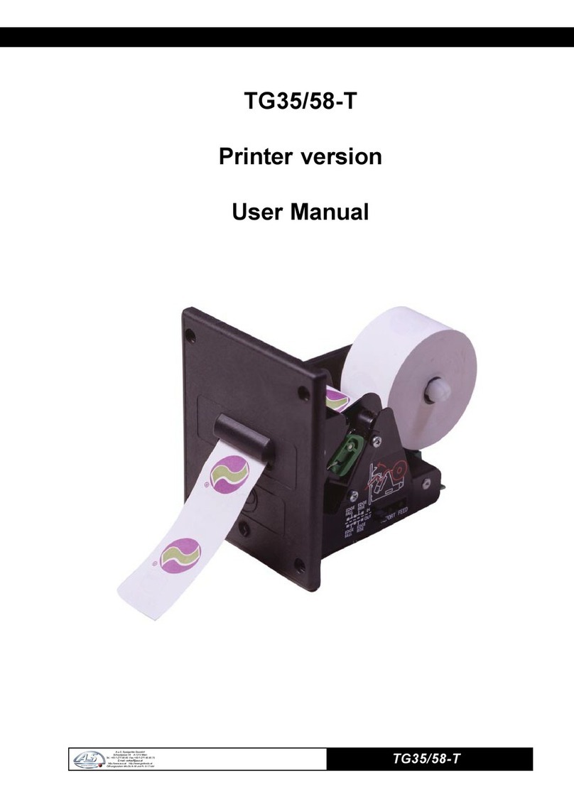
Custom Engineering TG35/58-T User manual

Custom Engineering
Custom Engineering KPM 216H II User manual

Custom Engineering
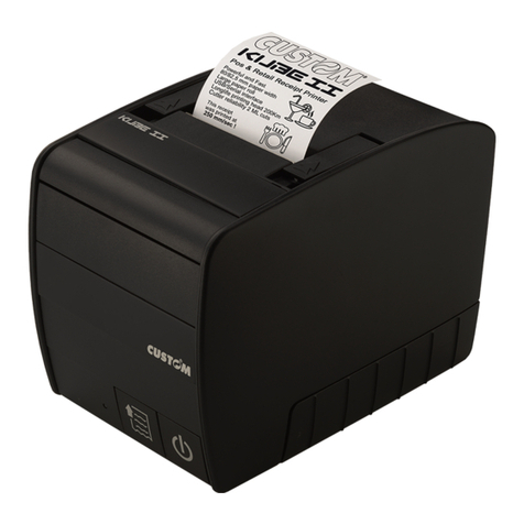
Custom Engineering KUBE II ETH User manual

Custom Engineering
Custom Engineering MT002-1 User manual

Custom Engineering
Custom Engineering My3-BT3B User manual

Custom Engineering
Custom Engineering TG02H User manual

Custom Engineering
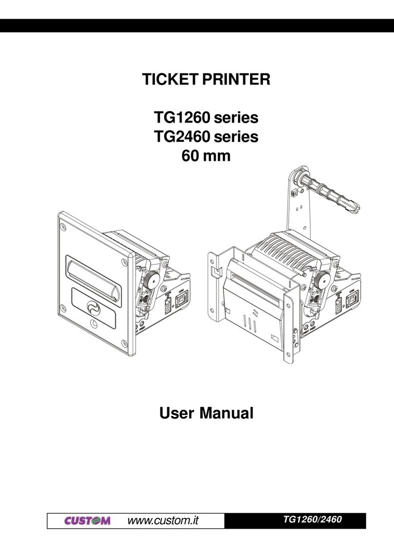
Custom Engineering TG1260 series User manual