Custom Engineering TG35/58-T User manual

TG35/58-T
TG35/58-T
Printer version
User Manual
www.custom.it

TG35/58-T
All rights reserved. Total or even partial reproduction of this manual in any
form, whether on paper or electronically, is strictly forbidden. While CUSTOM
ENGINEERING SPA guarantees that the information contained in this manual
has been carefully checked and verified, CUSTOM ENGINEERING SPA and
other resources utilized in its creation assume no responsibility for situations
arising from its use.
Feedback regarding any errors in the manual’s content or suggestions on
how it could be improved would be greatly appreciated. Since its products
are subject to continuous checking and improvement, CUSTOM
ENGINEERING SPA reserves the right to modify the information contained
in this manual without prior notice.
COD. DOME - TG35-58-T VERS. 1.33
Copyright 2001 CUSTOM ENGINEERING SPA – Italy
CUSTOM ENGINEERING SPA
Str. Berettine 2 - 43010 Fontevivo (PARMA) - Italy
Phone : +39 0521-680111 - Fax : +39 0521-610701
http: www.custom.it http: www.smice.com
To contact our Technical Support :
Phone. : +39 0521-680163 - Fax : +39 0521-680146

TG35/58-T
5
2
1
3
8
4
6
7
PRINTER COMPONENTS
A. TG35/58-T - exterior view
1- Printing mechanism
2- Report “Key”
3- Feed “Key”
4- Paper roll support
5- Case
6- Front panel
7- Led
8- Paper output
TG35/58-T
3
1 2
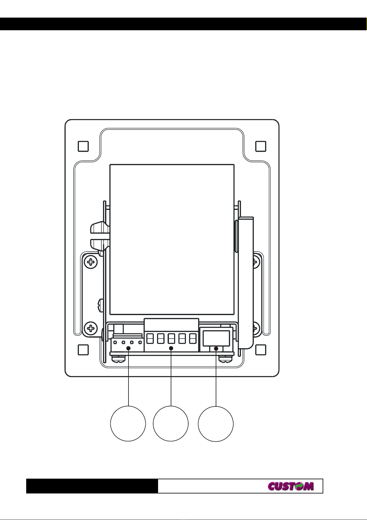
B. TG35/58-T - rear view
1- Power supply connector
2- Power supply connector and additional signals
3- TTL serial interface connector

TABLE OF CONTENTS
TG35/58-T
i
INTRODUCTION
MANUAL ORGANIZATION ............................................................................ 1
SYMBOLS USED IN THE MANUAL............................................................... 1
GENERAL SAFETY INFORMATION ............................................................. 1
UNPACKING THE PRINTER ......................................................................... 2
MAIN CHARACTERISTICS ........................................................................... 2
PRINTER DESCRIPTION ............................................................................. 3
1. INSTALLATION AND OPERATION
1.1 CONNECTIONS ................................................................................... 1-1
1.1.1 Power supply and Input/Output ...................................................... 1-1
1.2 SETUP .................................................................................................. 1-2
1.2.1 Configuration of REPORT and FEED keys ................................... 1-3
1.3 AUTOTEST .......................................................................................... 1-3
1.4 CAUTIONS ........................................................................................... 1-3
1.5 MAINTENANCE.................................................................................... 1-4
1.5.1 Using the control discs................................................................... 1-4
1.5.2 Changing the paper roll .................................................................. 1-4
2. INTERFACES
2.1 TTL SERIAL ......................................................................................... 2-1
3. PRINTER FUNCTIONS
3.1 COMMAND DESCRIPTIONS .............................................................. 3-1
3.1.1 ESC/POS Emulation ..................................................................... 3-1
4. TECHNICAL DATA
4.1 TECHNICAL DATA............................................................................... 4-1
4.2 DIMENSIONS ....................................................................................... 4-2

TABLE OF CONTENTS
TG35/58-T ii
APPENDIX A - ACCESSORIES AND SPARE PARTS
A.1 ACCESSORIES................................................................................... A-1
A.1.1 Power supply ................................................................................. A-1
A.1.2 RS232 cable adaptation ................................................................ A-2
A.2 SPARE PARTS .................................................................................... A-5

INTRODUCTION
TG35/58-T
1
MANUAL ORGANIZATION
In addition to the Introduction which contains information regarding the
symbols used in the manual, general safety information, instructions for
unpacking the printer and a brief description and main characteristics of the
machine, this manual is divided into the following chapters:
Chapter 1: Contains the information required for correct printer installation
and use
Chapter 2: Contains interface data
Chapter 3: Contains a description of printer controls
Chapter 4: Contains printer technical data
Chapter 5: Contains the character sets (fonts) used by the printer
SYMBOLS USED IN THE MANUAL
NOTE
Gives important information or suggestions for printer use.
WARNING
Information indicated by this symbol must be followed carefully to
avoid damaging the printer.
DANGER
Information indicated by this symbol must be followed carefully to
avoid damage or operator injury.
GENERAL SAFETY INFORMATION
•Read and retain the instructions which follow.
•Before cleaning the printer, be sure to pull out the electrical cable.
•Use a damp cloth to clean the printer. Do not use liquid or spray products.
•Do not operate the printer near water.
•When positioning the printer, make sure its cables will not be damaged.
•Use the type of electrical power supply indicated on the printer label. If
uncertain, contact your dealer.
•Do not block the ventilation openings.

INTRODUCTION
TG35/58-T 2
•Do not insert objects inside the printer as this could cause short-circuiting
or damage components that could jeopardize printer functioning.
•Do not spill liquids onto the machine.
•Do not carry out repairs on the machine yourself, except for the normal
maintenance operations given in the user manual.
•Unplug the printer from the electrical mains and call a specialized
repairman if any of the following conditions should arise:
A. the power supply connector is damaged
B. liquid has spilled into the printer
C. the printer has been exposed to rain or water
D. the printer is not functioning normally despite the fact that all
instructions given in the user manual have been followed
E. the printer has been dropped and the cover is damaged
F. printer performance is noticeably reduced
G. the printer is not working
UNPACKING THE PRINTER
Remove the printer from the carton, taking care not to damage the packing
materials which should be retained for future shipping/moving.
Make sure all components listed below are present and not damaged. If any
part is missing and/or damaged, contact customer service.
1. Manual (or CD-rom)
2. Printer
3. Discs control of paper roll
MAIN CHARACTERISTICS
The TG35/58-T printer is the ideal solution for :
• Gaming machines
• Vending machines
• Self-service machines
• Paper tear-off and anti-paper jam system.
• Optional RS232 cable adaptation.

INTRODUCTION
TG35/58-T
3
5
2
1
3
8
4
6
7
PRINTER DESCRIPTION
It is equipped with a 200 dpi thermal print mechanism that uses paper with a
width of 35/58 mm; it has a TTL serial interface (optional RS232 cable) and
is also equipped with a calendar clock (Real Time Clock).
The TG35/58-T printer consists of a case (5) onto which the following
components are fitted: thermal print mechanism (1), paper roll pin (4) front
panel (6) in PPO for installation on Gaming/Vending Machines.
• When the “REPORT” key (2) is pressed, it prints the printer operational
report.
• When the “FEED” key (3) is pressed, the paper can be fed forward
manually.
(Fig. 1)

INTRODUCTION
TG35/58-T 4
• The red Status LED (7) displays a printer hardware error status and the
winnings. The check is carried out“on line”, i.e. in the event of a
malfunctioning, the LED will starts flashing as follows:
DELSUTATSDELSUTATS DELSUTATS DELSUTATSDELSUTATSNOITPIRCSEDNOITPIRCSED NOITPIRCSED NOITPIRCSEDNOITPIRCSED
FFOsyawlAFFOretnirP
NOsyawlAstluafon–NOretnirP
)doirepgnolarofno(gnihsalfwolSdesiarrevocgnitliT
)doireptrohsarofno(gnihsalfwolSegasseMtuOrepaP
(Tab.1)
Table of contents
Other Custom Engineering Printer manuals

Custom Engineering
Custom Engineering TP 2000 User manual

Custom Engineering
Custom Engineering KPM 216H II User manual

Custom Engineering
Custom Engineering PLUS II User manual

Custom Engineering
Custom Engineering KPM150-H User manual

Custom Engineering
Custom Engineering s'print User manual

Custom Engineering
Custom Engineering Ticket Gaming TG35 User manual

Custom Engineering
Custom Engineering KPM150-H User manual

Custom Engineering
Custom Engineering VKP80II User manual

Custom Engineering
Custom Engineering s'print User manual

Custom Engineering
Custom Engineering My3-BT3B User manual


