CustomWorks ENFORCER G6 User manual

760 Crosspoint Drive
Denver, NC 28037
www.CustomWorksRC.com
Manufactured By:
#0926 ENFORCER G6 DIRECT DRIVE RACING KIT

REQUIRED READING...UNDERSTAND THIS MANUAL!
Thank You and Congratulations on purchasing the ENFORCER G6 DD! Within this kit you will nd a race winning
car with over 28 years worth of CUSTOM WORKS design and quality. In order for you to realize this race car’s
winning potential it is important to follow the written text along with the pictures included. The steps required to
build this car are very easy, as long as you read before you build.
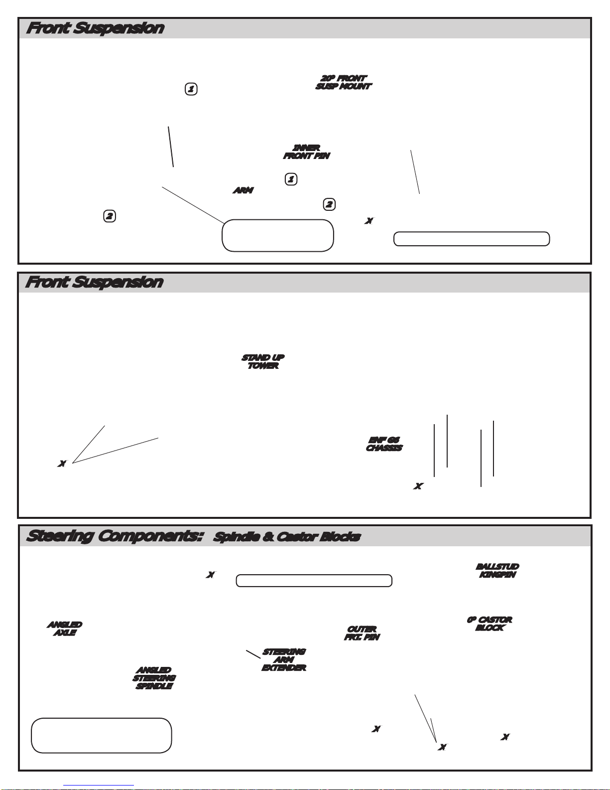
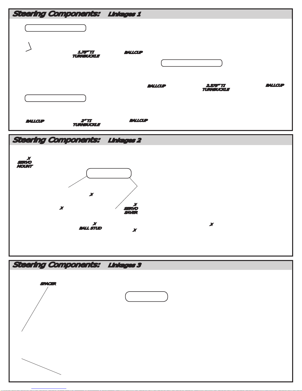
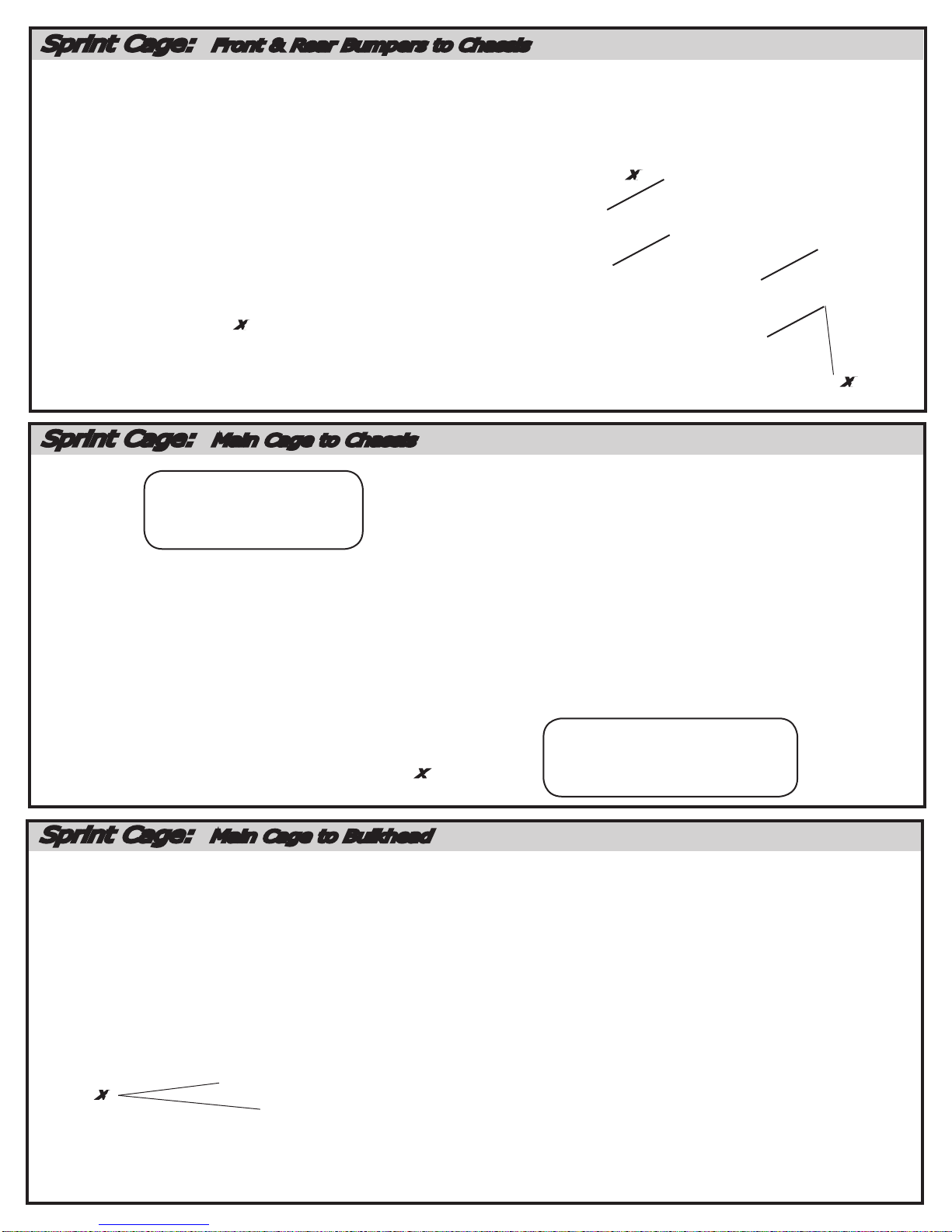
The instructional format for building this car is to use the “named” bag titled at the top of each section. Each
section will be broken down into “steps” thru the section . The bag containing the chassis holds a variety of
unique parts for your kit. Parts and hardware needed to complete each step will be found in the individual
“named” bag plus the few unique items from the chassis bag you may need for that particualar step. All parts are
referred to by their replacement part number in the instructions.
Considering the various dirt or clay surfaces that Dirt Oval cars are raced on today, the Enforcer has been
designed to be competitive on high bite and well groomed clay tracks with foam racing tires. The instructions
will build the kit using the most verastale set-up Custom Works has found in testing on different types of tracks,
however there are various other suspension congurations available to you that you may nd more suitable for
your local track. For updates and more proven set-ups login to CustomWorksRC.com or check out our video’s on
our YouTube channel.
BUILDING TIPS...
-Parts are made with tight tolerance and held to the side of a “snug” t as wear is expected over time. Try as we
may, occasionally a burr may remain in a part and t more tightly than desired. It is ok to use 400 Grit Sandpaper
or a .125” drill to SLOWLY relieve a part from time to time. Suspension components should always pivot and swivel
freely but not sloppily.
-Using some type of thread locking uid is suggested for all parts where metal screws thread into other metal parts.
We suggest using a lite setting strength thread lock for the reason you may want to take the screw out one day.
Remember it only takes a very small amount to secure the screw.
-Do NOT use power screwdrivers to drive screws into parts. The fast rotation speed can melt and strip plastic parts
or cross-thread into the aluminum parts.
-Lightly sand the edges of graphite pieces using a medium grade sandpaper to avoid splinters. Run a thin bead of
Super Glue around the edges to give pieces greater durability.
SUGGESTED TOOLS
400 Grit Sandpaper Wire Cutters Blue Loctite
Hobby Scissors X-Acto Knife 3/16” Wrench
Small Needle Nose Pliers Phillips Head Screw Driver
HARDWARE GUIDE
-Use the hardware below to help identify the appropriate screw to use throughout the manual.

Steering Components: Spindle & Castor Blocks
3213
ANGLED
STEERING
SPINDLE 8122
5253 X2
5292 X2
7224
ANGLED
AXLE
5217
1255 X2
7209
BALLSTUD
KINGPIN
3400
0
O
CASTOR
BLOCK
4244
OUTER
FRT. PIN
- HELP ALIGN AXLE
AND SPINDLE HOLES
USING A .125” DRILL BIT
BY HAND ONLY.
*MAKE L & R ASSEMBLY*
7209 X2
5230
1255
1292
STEERING
ARM
EXTENDER
Front Suspension
5253 X2
3508
STAND UP
TOWER
5262 X4
Front Suspension
1
2
4246
INNER
FRONT PIN
5212
5284
3251
ARM
2320
20
O
FRONT
SUSP MOUNT
*MAKE L & R ASSEMBLY*
3502
ENF G6
CHASSIS
THREAD 5284
UNTIL FLUSH
WITH THIS FACE.
5292 X2
2
1

3246
SLIDE
NUT
Steering Components: Linkages 1
5235
BALLCUP
*MAKE 2 LINKAGES*
*MAKE 2 LINKAGES*
5213 5223
1.75” TI
TURNBUCKLE
5235
BALLCUP
5235
BALLCUP 5225
2” TI
TURNBUCKLE
Steering Components: Linkages 2
Steering Components: Linkages 3
1255
SPACER
5257
SNAP BALL CUPS
ONTO BALL STUDS
5217
-FRONT CAMBER LINKS
-REAR CAMBER LINKS
5235
BALLCUP
*MAKE 2 LINKAGES*
5235
BALLCUP 5226
2.375” TI
TURNBUCKLE
-STEERING LINKS
5263 X2
5244 X2
SERVO
MOUNT
5205 X2
5237 X2
SERVO
SAVER
8121 X2
BALL STUD
5253 X2
5212 X2
SCREW PROVIDED
WITH YOUR SERVO
5263 X2

CVD & Drive Assembly: Bearing Carrier & CVD
LOCTITE
GREASE
7217
DRIVE
PIN
7215 (SHORT) X1
DRIVE BONE
7216
DRIVE
AXLE
7211
COUPLING
7211
SET
SCREW
7214 (MED) X1
DRIVE BONE
5292 X2
4245
REAR OUTER
SUSP PIN
1255 X4
SPACER
3241
BEARING
CARRIER
1226 X2
BEARING
TIP: FILE SMALL
FLAT HERE FOR CVD
SET SCREW, LESS
CHANCE OF PIN LOSS.
Rear Suspension: Chassis Locations
1
2
5251
5263
5205 X2
3242
SHORT
ADJ. ARM
3246
OUTER
SWING
5259
5212
3246
SLIDE
NUT
*MAKES LEFT ARM*
-INSERT SLIDE NUT
ASSEMBLY OPPOSITE AS
SHOWN TO MAKE RIGHT
ARM.
THICK AREA OF 2236 SUSP MOUNT
TOWARD REAR OF CAR!!!
2236
SUSP. MOUNT
4247
REAR INNER
PIN
5262 X2
5264 X4
MIDDLE
POSITION
5292 X2
USE BRASS SHIM
HERE TO REMOVE
PLAY WHEN HOUSED
IN 3242
INNER
POSITION
Rear Suspension: Tower & Suspension Arm Assembly
5252 X6
8122 X2
BALL STUD
2224 X2
MOUNT
BLOCK
3512
REAR BULKHEAD
3 HOLES
THIS SIDE
5253 X6
5217 X6
3514 X2
REAR
TOWER EARS
INNER
POSITION
MIDDLE
POSITION
2218 X2
CAMBER LINK
STANDOFF

Transmission
4124
BEARING
CARRIER (R)
4123
RIGHT
BULKHEAD
4121
LEFT
BULKHEAD
4122
BEARING
CARRIER (L)
5252 X2
4131 X2
BEARING
5252 X2
5253 X2
3519
TRANS
BRACE
USE SMALL
AMOUNT OF DIFF
LUBE ON BLADE.
4382
BLADE
STRETCH BLADE OVER
PIN ON DRIVE BONE
5262 X5
*MOUNT DD BULKHEADS*
Direct Drive Diff Assembly
DIFF LUBE
DIFF LUBE
DIFF LUBE
4129
DIFF BOLT
4361
DIFF BOLT
COVER
4360 X3
THRUST
WASHER
4367
THRUST
BEARING
4125
RIGHT
OUTDRIVE
4133
BEARING
8035
DIFF RING
4361
T- NUT
4362
DIFF
SPRING
4126
LEFT
OUTDRIVE
4133
BEARING
8035
DIFF RING
4132 X12
CERAMIC
DIFF BALLS
4887
SPUR GEAR
48P / 87T
Thread the Diff Bolt Outdrive with the Allen
Key into the assembled outdrive with the T-Nut
until you feel the Diff Spring begin to compress.
When diff spring fully compresses threading will
be come difcult, STOP HERE!
Back off 1/2 turn from this point, the thrust load
on your diff should be close.
CVD & Drive Assembly: Installation
7203
ROLL PIN
1255
SPACER
8122
BALL STUD
7047 X1
(THICK)
1
2
SNAP BALL CUPS
ONTO BALL STUDS
STRETCH BLADE
OVER PIN ON DRIVE
BONE
4382
BLADE
4382 X2
DRIVE
BLADES
7047 X1
(THIN)

Transmission
3228
SET
SCREW
3228
SHORT
BODY POST
5252 X2
3228
POST
COLLAR
4130
BODY POST
MOUNT
5283
Shocks: Assembly
1250 X2
O-RING
1429 MEDIUM SHAFT
1430 SHORT SHAFT
1438
EYELET
CAP
5230 X21436
PISTON
(MEDIUM)
1415 MEDIUM BODY
1414 SHORT BODY
1464 X2
GUIDE
1417
SEAL
CAP
1437
BLADDER
1433
SPRING
COLLAR
5235
BALL
CUP
NOTE!!! USE SMALL AMOUNT
OF DIFF LUBE OR SHOCK FLUID ON
O-RINGS BEFORE INSERTING THE
SHOCK SHAFT! THIS IS TO PREVENT
TEARING THE O-RING. THREAD BALL CUP
UNTIL EVEN WITH END
OF THREADS ON SHAFT.
INSERT O-RING
INTO COLLAR
2) Slowly move the shaft
up and down several
times to allow air bubbles
to escape to the top.
1) Holding the
shock upright, ll
with oil until just
under the top of
the body.
3) Rell shock
as instructed in
Step 1 if need
be.
5) Move the shock shaft in and out a few
times and then push it all the way in. It
should be easy to push the shaft in until the
ball cup is within 1/16” of hitting the body.
4) Place Bladder onto top of
shock, small amount of oil
should displace.
Thread the Eyelet Cap
assembly onto the
Shock Body until it is
hand tight.
Oil should seep
out of the bleed hole
in the Eyelet Cap.
OIL
OIL
SUGGESTED
35 WT R/C
SHOCK OIL.
Shocks: Fluid Filling
6) Then the shaft should
push itself out to its full
length slowly.
7) If the shock does not push out
this far there is not enough oil in it.
Add just a little oil and try steps 5-6
again.
OIL
8) If the shock rebounds
too fast , or you cannot
push the shaft in until the
ball cup gets close to the
body, there is too much oil.
Simply remove the Eyelet
Cap and retighten the cap,
typically this will allow just
enough oil to escape to be
successful without un-
der-lling the shock.
MAKE (2) OF EACH!!!
A) SHORT BODY WITH
SHORT SHAFT
B) MED BODY WITH
MED SHAFT
1407 X4
Spring Bucket

Shocks: Mounting
5277
2214
STAND OFF
1408
SHOCK
BUSHING
5217
8122
1408
SHOCK
BUSHING
8122
2ND
HOLE FROM
TOP
2214
STAND
OFF
5217
5277
Battery Mounts
3266 X2
Battery Mount 3009
Battery
Straps
5263 X4
USE THE BATTERY LOCATION
SHOWN TO START.
- MOVE THE BATTERY AND ANY
WEIGHT BACK FOR MORE DRIVE
OFF THE CORNER.
- MOVE THE BATTERY AND ANY
WEIGHT FRONT FOR MORE ON
POWER STEERING.

Sprint Cage: Front & Rear Bumpers
5254 X4
3433
Front Bumper
3435
Offset
Rear Connector
3435 X2
Connector Post
1” Length
3433 X2
Front
Down Tubes
5254 X2
Sprint Cage: Nerf Bar & Cage Connector
3434 X2
Rear Bumper
3434
Stud
THREAD STUD ON TO
BUMPER, THEN THREAD OTHER
BUMPER ON TO THE STUD UNTIL
THE POSTS MEET.
3431
Main
Cage Half
3432
Nerf Bar 5254 X2
*MAKE L & R ASSEMBLY*
5255
3421
Wing Slide
Bushing 5217
Sprint Cage: Main Cage
5254 X2
5254
5280
Hole Head
Screw
5254
5254
3433
Halo Bars
3431 X2
Body Post
Bar
5254 X4
3435
Cage
Connector
3435
Connector
Post 1”
NOTE: SELECT CORRECT
“CAGE CONNECTOR” AND
“CONNECTOR POST” AS
SHOWN IN DIAGRAM.
FOR FINAL ASSEMBLY
BODY PANELS
MOUNT BETWEEN NERF BAR AND OTHER MOUNT-
ING SCREWS FROM THIS STEP FORWARD. YOU MAY
CONSIDER PREPARING YOUR BODY PANELS NOW TO
AVOID DOUBLE-WORK.

Sprint Cage: Main Cage to Chassis
Sprint Cage: Main Cage to Bulkhead
5263 X2
5264 X2
5253 X2
5263 X4
CAGE POSTS MOUNT
IN “FRONT” HOLES OF
LOCATION WHERE THEY
MEET TO THE CHASSIS.
BE SURE CAGE SIDE
PANELS DO NOT TOUCH SUSP
ARMS OR CAMBER LINKS IN
MOTION OF TRAVEL!
5252 X2
Sprint Cage: Front & Rear Bumpers to Chassis

Body Panel Prep & Mounting
*Do these steps BEFORE painting any of the body panels !!!
The body panels in the pictures are painted so that it is easier to see them in these instructions.
- Nose Pieces (2 types): From the single mold, choose from based on your taste or handling desire.
1) The nose on the left is a conventional type nose typically seen on real sprint cars. Its effect for the RC
car is less downforce. Its the better RC racing choice if you have a very low bite loose dirt track or need to
numb the steering feel of your car.
2) The nose on the right is a much more aggresive nose used primarily for most RC dirt ovals. It provides
the most downforce possible but is easier to damage due to its proximity to the front of the car and track.
Trimming:
- To make following the trim lines easiest, trace the trim lines on your body panels with a Sharpie pen so
they follow the path in the panels shown above. Other trim lines exist on the mold but are not the best t
for your kit.
- Drill a .125” hole on the dimpled dot molded on the panel in the location shown above with the “O”.
- Make a body post hole (.200”) on the spot marked with the “X”
- Slight additional clearance needed for the front bumper in the areas marked with a “Z”
O
OO
O
X
Z
Z
X
Hood, Headers & Tank: Follow the molded lines on the mold to cut the body parts out. Make body
post hole (.200”) on the “X”. Drill a .125” hole on the dimpled dot on the headers marked with an “O”.
X
X
Follow the
“notch” in
the body lines.
X
OO
Body Panels: After mounting the panels to the cage, follow
the dotted lines shown to make clearance for suspension to move.
Attach the Headers to the side panel using the nylon screws and
nuts.
- No need to
trim this area unless
it interferes with
your shock location.
Remove to give
clearance for susp
movement. Do both
sides of car.

Mounting Low DF Nose to Cage Mounting High DF Nose to Cage
- In the hole shown in the above image marked with
the “X”, use (1) 5253 screw to fasten the body panel
to the Front Down Tubes.
- In the hole shown in the above image marked with
the “X”, use (1) 5253 screw to fasten the body panel
to the Front Down Tubes.
- Use a .113” drill or smaller thru the (2) remaining
holes in the Front Down Tube to make the holes
marked by the “O”.
X
OO
X
- Re-attach the Front Bumper using (2) 5254 Screws in the remaining holes. Optional front wing mounts
will attach using the screws noted with the “X”.
5254 X25253 5254 X25253
X
X
X
X
Top Wing: Assemble the wing kit using the instructions provieded inside the wing kit. Mount the wing to
the car and it should look just like the car shown below.

- Bent Suspension Pins: Remove shocks to check
free movement.
- Bound Ball Joint: Should spin free on balls while
mounted to the car.
- Bent or Loose Camber Links
- Wore out Bearings or Completely Seized Bearings
- Chunked Tire: Check to see if Foam or Rubber Tire
is still glued to wheel.
- Loose Screws: Especially Chassis Screws, add Blue
Loctite to prevent.
- Shocks: Either Bound-up or Out of Oil. Must swivel
freely on mounts.
- Foreign Objects: Unlucky Dirt/Stones preventing
Suspension or Steering Movement.
- Blown Differential
- Radio Problem: Bad Servo, Weak Servo Saver
Spring, Transmitter Pot blown.
- Decrease Wing Angle
- Decrease Spoiler on Wing
- Heavier Rear Spring
- Softer Front Spring
- Use Rear Sway Bar
- Try Softer Front Compound Tire
- Try Harder Rear Compound Tire
- Lower Front Ride Height
- Raise Rear Ride Height
- Thread Shock Collar UP on
Right Front
- Thread Shock Collar DOWN on
Right Rear
- Decrease Rear Toe
- Decrease Castor
- Add Rear Toe Stagger or Increase
the difference
- Increase Wing Angle
- Add Spoiler to Wing
- Softer Rear Spring
- Heavier Front Spring
- Use Front Sway Bar
- Try Harder Front Compound Tire
- Try Softer Rear Compound Tire
- Raise Front Ride Height
- Lower Rear Ride Height
- Thread Shock Collar
DOWN on Right Front
- Thread Shock Collar UP on
Right Rear
- Increase Rear Toe
- Increase Castor
- Decrease Rear Toe Stagger or
Decrease the difference
Car Is Loose (oversteers):
Car Pushes (understeers): Car Is Erratic:
TUNING TIPS:
In this manual are some general guidelines for optimizing handling
performance. Be SURE to check out the CustomWorks RC channel on YouTube for more
indivdualized explanation of the many tuning features of your new car. None of these “tips” are
EVER set in stone. On any given day this manual or any chassis engineering book or guru can be
proved wrong by the stop watch. A good way to approach chassis set-up is to try one change,
practice it, think how the car felt different from before, and compare lap times from the stop
watch…..this will never fail.
CONGRATULATIONS!!!You have now completed the assembly process of your new
CustomWorks Enforcer. In the next section of this manual you will nd some basic setup hints and
advice. It is important to remember that all tracks and racing surfaces are different. Therefore the
suggestions we give you are general in nature and should by no means be treated as the only options.
MAINTNANCE:Occasionally dirt will get into the moving and pivoting locations in your car. It is
best to periodically clean your car during the race day to keep all the suspension components moving
freely. Read the tips below to keep your car running at its best!
-Begin by removing the majority of the dirt using a small brush, toothbrush, or compressed air.
-Compressed air is ok to use, be mindful to not FORCE the dirt into the radio gear, transmission or
bearings.Typically these items only have dirt on them, hitting the dirt with compressed air puts dirt IN
these parts!
-Tires, either foam or rubber are best cleaned using water or cleaners like Simple Green (TM). Simple
Green also does a great job of cleaning car parts as well. Lightly spraying car parts (NOT radio
components transmission, bearings) with Simple Green and blowing off with compressed air or wiping
the parts using a paint brush is a great way to clean in hurry.
-Another R/C friendly cleaner is WD-40 (TM). After the car is clean, very lightly spray the car
components and bearings (NOT radio components transmission). Use your brush or compressed air
to remove the extra WD-40. This will lube your bearings and leave a protective coating on the parts
making it easier to remove dirt later. Other products related to R/C and motorcross sell spray coatings
that accomplish the same or better protection.
-Differential Maintnance is needed when the action of the diff feels “notchy”. This occurs when the car
is loose of the corner, spinning the LR tire extremely and/or when there is more motor in the car than
necessary. Usually cleaning the diff parts, re-sand the thrust and diff plates with 400 grit paper, and
lube appropriately will be all that is needed to bring back to new. Ignoring your diff will lead to handling
woes and increased trans temps, which will cause part failure.

SET-UP GLOSSARY:
Caster: Angle of the kingpin in relation to a vertical plane as viewed from the side of the car.
Increasing the angle will make the car more stable out of the turn and down the straights and increase
steering entering a turn. Decreasing the angle will make the car feel more “touchy” at high speeds and
help steering while exiting the turn.
Camber Gain: Angle of the Camber Link relative to the Suspension Arm. Lowering the camber link
on the shock tower OR raising the camber link on the castor block will INCREASE the camber angle of
the tire when the suspension is compressed. Raising the camber link on the shock tower OR lowering
the camber link on the castor block will DECREASE the camber angle of the tire when the suspension is
compressed. There is not a “correct” set-up and once again too much of anything is generally bad. This
will help change the “feel” of the car thru the turns.
Camber Link Length: Comparing this to the length of the Suspension Arm from each pivot point and
keeping the Camber the same, making the link shorter will decrease traction for that corner of the car
while making it longer will increase traction for that corner of the car. Once the camber link is equal to
or greater than the Suspension Arm pivots, the gain of traction ends. Also a shorter camber link will
increase camber gain and a longer decrease camber gain.
Shock Angle: Leaning the shock toward the car is effectively like changing to a softer spring.
Standing the shock closer to vertical is effectively like changing to a stiffer spring. Try when the car is
working well and when one spring change is TOO much for your set-up.
Ride Height: Check by pushing the chassis down once or twice to simulate bumps on the track.
Having the front end higher than the rear will make the car increase rear traction especially out of
the turn. Having the front end lower than the front will make the car increase front traction especially
entering the turn. Generally its safe to start the car with the ride heights even.
Rear Toe-In: Front edge of car tires point toward the chassis as viewed from above the car.
Increasing the angle toward the car will increase rear traction while decreasing front traction.
Decreasing the angle will do the opposite.
SETUP GUIDELINES:
When looking for the “perfect set-up” it is important to remember 2 things...
1) Keeping things simple is best.
2) As you are making your set-up change, the track is changing too! Ask a local racer what the track
usually does from begining to end, especially day to night.
- Start your car’s ride height with it equal at all four corners to start. Use the shock collars to adjust
ride height by measuring the distance under the chassis when the car is sitting on a FLAT & LEVEL
surface. With foam tires in the 2.6” range, .600” to the top of the chassis (1/2” under the chassis) is a
good measurement to start with.
- Shock collars can only jack weight and adjust the car’s handling when the car makes ALL 4 shocks
squat when the car is set down. Use the RF shock collar to adjust how the car ENTERS the corner. Use
the RR shock collar to adjust how the car exits the corner ON-POWER. Use the LF shock collar to make
the car turn in less, and off the corner more.
- It is best to have a little bit of brake drag when you let off the gas, this will allow for a more
controlable car in ALL conditions. Increasing how much the brake drags will make your car turn into the
corner harder but can make the car also much more loose to drive into the corner. With most speed
controls today a drag brake strength of 10-20% is a good range to work with.

SET-UP GLOSSARY:
Caster: Angle of the kingpin in relation to a vertical plane as viewed from the side of the car.
Increasing the angle will make the car more stable out of the turn and down the straights and increase
steering entering a turn. Decreasing the angle will make the car feel more “touchy” at high speeds and
help steering while exiting the turn.
Camber Gain: Angle of the Camber Link relative to the Suspension Arm. Lowering the camber link
on the shock tower OR raising the camber link on the castor block will INCREASE the camber angle of
the tire when the suspension is compressed. Raising the camber link on the shock tower OR lowering
the camber link on the castor block will DECREASE the camber angle of the tire when the suspension is
compressed. There is not a “correct” set-up and once again too much of anything is generally bad. This
will help change the “feel” of the car thru the turns.
Camber Link Length: Comparing this to the length of the Suspension Arm from each pivot point and
keeping the Camber the same, making the link shorter will decrease traction for that corner of the car
while making it longer will increase traction for that corner of the car. Once the camber link is equal to
or greater than the Suspension Arm pivots, the gain of traction ends. Also a shorter camber link will
increase camber gain and a longer decrease camber gain.
Shock Angle: Leaning the shock toward the car is effectively like changing to a softer spring.
Standing the shock closer to vertical is effectively like changing to a stiffer spring. Try when the car is
working well and when one spring change is TOO much for your set-up.
Ride Height: Check by pushing the chassis down once or twice to simulate bumps on the track.
Having the front end higher than the rear will make the car increase rear traction especially out of
the turn. Having the front end lower than the front will make the car increase front traction especially
entering the turn. Generally its safe to start the car with the ride heights even.
Rear Toe-In: Front edge of car tires point toward the chassis as viewed from above the car.
Increasing the angle toward the car will increase rear traction while decreasing front traction.
Decreasing the angle will do the opposite.
When looking for the “perfect set-up” it is important to remember 2 things...
1) Keeping things simple is best.
2) As you are making your set-up change, the track is changing too! Ask a local racer what the track
usually does from begining to end, especially day to night.
- Start your car’s ride height with it equal at all four corners to start. Use the shock collars to adjust
ride height by measuring the distance under the chassis when the car is sitting on a FLAT & LEVEL
surface. With foam tires in the 2.6” range, .600” to the top of the chassis (1/2” under the chassis) is a
good measurement to start with.
- Shock collars can only jack weight and adjust the car’s handling when the car makes ALL 4 shocks
squat when the car is set down. Use the RF shock collar to adjust how the car ENTERS the corner. Use
the RR shock collar to adjust how the car exits the corner ON-POWER. Use the LF shock collar to make
the car turn in less, and off the corner more.
- It is best to have a little bit of brake drag when you let off the gas, this will allow for a more
controlable car in ALL conditions. Increasing how much the brake drags will make your car turn into the
corner harder but can make the car also much more loose to drive into the corner. With most speed
controls today a drag brake strength of 10-20% is a good range to work with. Final Drive Chart: The chart provided below gives you the nal drive of the motor to spin the axle
1 revolution. This chart is NOT just the pinion and spur, but has the transmission ratio included as
well.
Rear Toe Stagger: Difference in the amount of Rear Toe-In among the rear tires. Typically used
only on high bite tracks with MORE toe-in on the Left Rear tire than the Right so the rear of the car
helps turn the car LEFT under acceleration.
Wheelbase (Front End): Wheelbase is the distance between the front and rear axles. Running
the entire front end assembly in the forward position makes the wheelbase longer and therefore
more stable on long/fast tracks with owing turns. Running the entire front end assembly in the rear
position make the wheelbase shorter and therefore more suitable for short-tracks where you are
constantly turning.
Wheelbase (Rear End): This adjustment uses the plastic spacers on the kingpin the rear bearing
carrier rides on. With the spacers in front of the carrier it will lengthen the wheelbase but will
increase steering. If the spacers are behind the carrier it will shorten the wheelbase but increase
rear traction. This is completely backwards from how it works for the Front End only because in
the rear of the car you have the weight of the motor and the torque it creates. Shortening the
wheelbase here makes more of the car hang over the rear tires and promotes more weight transfer.
- To determine the nal drive in your car:
1) Divide the Spur Gear by the Pinion Gear, which
equals a “Ratio”.
2) Multiply the “Ratio” by the “Transmission Ratio”
which will equal your “Final Drive”.
***Transmission Ratio = 2.4 for this car.***
- Gearing choice can vary greatly depending
on track size, surface type, amount of traction,
you motor and driving style. For starters consult
your local hobby dealer or fellow racer at your
local track for the ideal gear choice for your
application.


LONG SHORT
INNER SUSP MOUNT
SHORT LONG
TOE:
___________
SWAY BAR:
NONE ______________
DRIVER: _____________________________
EVENT:_______________________________
CLASS:_______________________________
TRACK: ______________________________
Clay Hard Packed Loose Dirt
Carpet Asphalt Concrete
Flat Banked True Oval Tri-Oval
Traction: High Medium Low
_________________
CAMBER
_________________
CASTOR
+10O +5O 0O -5O -10O +10O +5O 0O -5O -10O
RIGHT
ACKERMANN
OUTER MIDDLE INNER INNER MIDDLE OUTER
LEFT FRONT
BODY LENGTH
SHORT MED LONG
SHAFT LENGTH
SHORT MED LONG
SPRING:________________
OIL: ___________________
PISTON:________________
LENGTH:________________
COLLAR:________________
SHOCKS
SHOCK LENGTH
COLLAR
LENGTH
FRONT SUSPENSIONLEFT
________________
AXLE SHIMS
________________
OUTER CAMBER LINK LOCATION
OUTER INNER INNER OUTER
0O ANGLED
KINGPIN INCLINE
ANGLED 0O
____________
CAMBER RATE SHIMS
_____________
SUSPENSION LOCATION
OUTER MIDDLE INNER INNER MIDDLE OUTER
KICK-UP:
15O LO 15O HIGH 20O LO 20O HIGH 25O 35O
RIGHT FRONT
BODY LENGTH
SHORT MED LONG
SHAFT LENGTH
SHORT MED LONG
SPRING:________________
OIL: ___________________
PISTON:________________
LENGTH:________________
COLLAR:________________
LEFT REAR
BODY LENGTH
SHORT MED LONG
SHAFT LENGTH
SHORT MED LONG
SPRING:________________
OIL: ___________________
PISTON:________________
LENGTH:________________
COLLAR:________________
RIGHT REAR
BODY LENGTH
SHORT MED LONG
SHAFT LENGTH
SHORT MED LONG
SPRING:________________
OIL: ___________________
PISTON:________________
LENGTH:________________
COLLAR:________________
__________________
CAMBER
__________________
RIGHTREAR SUSPENSIONLEFT
WHEEL SPACERS
.250” .125” NONE NONE .125” .250”
ANTI-SQUAT SHIMS
3O1.5ONONE NONE 1.5O3O
ROLL CENTER SHIMS
.125” .060” NONE NONE .060” .125”
BEARING CARRIER SPACING
RIGHT:
FWD 1-OFF FWD MIDDLE 1-OFF REAR REAR
LEFT:
FWD 1-OFF FWD MIDDLE 1-OFF REAR REAR
OUTER CAMBER LINK LOCATION
OUTER INNER INNER OUTER
BEARING CARRIER PIN HEIGHT
HIGH R.C. LOW R.C. (NEAR AXLE) LOW R.C. HIGH R.C.
RF:
___________________________________________________
LF:
___________________________________________________
RR:
___________________________________________________
LR:
___________________________________________________
CLEANED WITH:
_________________________________________
TRACTION ADDITIVE:
____________________________________
NOTES:
________________________________________________
______________________________________________________
______________________________________________________
______________________________________________________
______________________________________________________
______________________________________________________
COMPOUND DIAMETER INSERT
TIRE TYPE:
FOAM STREET RUBBER LOOSE
-SHADE IN MOUNTING
LOCATIONS ON SUSPEN-
SION ARMS, BEARING
CARRIER AND SHOCK
TOWER.
TIRES & TRACTION
____________________
TOE
____________________
SHOCK LOCATION:
AB C D
A
SHOCK LOCATION:
AB C
A
C
D
RIGHT LEFT
-SHADE IN MOUNTING LOCATIONS
ON SUSPENSION ARMS, BEARING
CARRIER AND SHOCK TOWER.
SHOCK
LOCATION:
ON SUSP ARM:
AB C D
ABD
C

RECEIVER
AS SHOWN
___________
SPEED CONTROL
AS SHOWN
________________
BATTERY
POSITION
FR
SPEED
CONTROL
RECEIVER
RIDE HEIGHTS
BY LOCATION
:
LF:___________ RF:___________
LR:___________ RR:___________
MEASURED FROM:
TOP OF CHASSIS BOTTOM OF CHASSIS
CORNER WEIGHTS:
LF:___________ RF:___________
LR:___________ RR:___________
MAX CHASSIS HEIGHT:
LF:___________ RF:___________
LR:___________ RR:___________
MEASURED FROM:
TOP OF CHASSIS BOTTOM OF CHASSIS
-MEASURED “RACE READY” WITHOUT THE TOP WING
OVERALL:_______________________
LF
RF RR
LR
POWER SETTINGS
MOTOR:______________________
AMP DRAW:___________________
TIMING:______________________
PINION:______________________
SPUR:________________________
SPEED CONTROL:______________
”BLINKY” OPEN
SETTINGS:___________________
_____________________________
_____________________________
BATTERY:_____________________
MOTOR TEMP AFTER RUN:_______
NOTES:
_______________________________________________________________________________
_______________________________________________________________________________________
_______________________________________________________________________________________
_______________________________________________________________________________________
_______________________________________________________________________________________
_______________________________________________________________________________________
_______________________________________________________________________________________
AERO
MAIN WING
6X6
7X7
FRONT WING
NONE SMALL
LARGE
HOOD TYPE
TRADITIONAL
SCOOP (HIGH DF)
MAIN WING LOCATION
LOW WING
HIGH WING
1 2 3 4 5 6
1 2 3 4 5 6 7
AB
C
D
TRANNY TYPE:
DIRECT DRIVE
GEAR BOX
TRANNY LOCATION:
FORWARD
REAR
BATTERY MOUNT
AS SHOWN
LAID DOWN
SERVO MOUNT
AS SHOWN
DIRECT/NOSE
ADDED WEIGHT:
FRONT____________
MIDDLE___________
REAR _____________
Table of contents
Other CustomWorks Motorized Toy Car manuals

CustomWorks
CustomWorks ENFORCER GSX User manual

CustomWorks
CustomWorks Rocket Pro-Comp User manual

CustomWorks
CustomWorks NITRO ROCKET KIT 0715 User manual

CustomWorks
CustomWorks Aggressor SE 0802 User manual

CustomWorks
CustomWorks Dominator User manual

CustomWorks
CustomWorks Intimidator SE3 DD 0914 User manual

CustomWorks
CustomWorks Outlaw 4 User manual

CustomWorks
CustomWorks INTIMIDATOR GSX2 User manual

CustomWorks
CustomWorks Intimidator SE User manual

CustomWorks
CustomWorks Rocket Stage-3 User manual