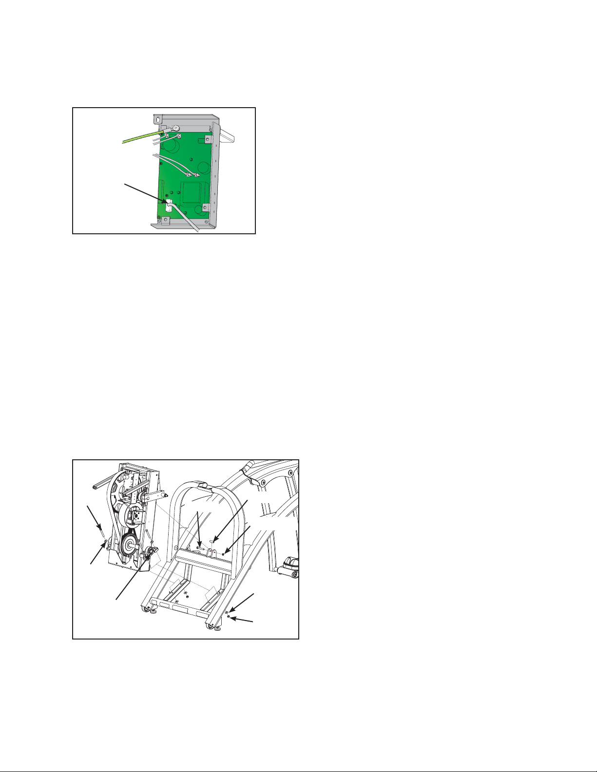
manuals.online logo
Brands
  1. Home
  2. •
  3. Brands
  4. •
  5. CYBEX
  6. •
  7. Fitness Equipment
  8. •
  9. CYBEX Arc Trainer 610AK019-4 User manual

CYBEX Arc Trainer 610AK019-4 User manual

Arc Trainer®Main Frame Assembly
Kit No. 610AK019-4
Kit No. 630AK019-4
Installation Instructions
NOTE: This instruction sheet describes how to replace
the main frame assembly in the Arc Trainer 610A.
Tools Required
• 3/16” Allen wrench • Rubber mallet
• 7/32” Allen wrench (2) • Side cutter
• 9/16” Socket • Punch
• 9/16” Open end wrench • Torque wrench
• 6” Phillips screwdriver
NOTE: Two people is recommended for this procedure.
1. Read and understand all instructions thoroughly
before installing this kit.
2. Verify kit contents.
A. Main Frame Assembly (1)
B. Foot Pad (2), 11090-405
C. CE Decal (1), CM000242
D. Loctite 242 (2), YA000201
3. Elevate the unit and disconnect the power
source.
A. Elevate the unit to a minimum of level 7 incline.
B. While the unit is elevated, turn the main power
switch to the off (0) position and unplug the
power cord from the power outlet.
4. Remove console
A. Using a 7/32” Allen wrench, remove the four
.375-16 x 1.50 BHCS (Button Head Cap Screw)
and four washers. See Figure 1.
B. Unplug upper display cable from lower display
cable.
C. Set console aside. NOTE: Console will be
attached to the new frame later.
5. Remove lower left linkage rod.
A. Using a 3/16” Allen wrench, remove each SHCS
(Socket Head Cap Screw), spacer, cap and
washer securing both ends of the lower linkage
rod. See Figure 2
B. Remove lower linkage rod and set aside along
with hardware removed in step 5A. NOTE: These
will be attached to the new frame later.
C. Repeat steps 5A and 5B to remove other linkage
rod.
6. Remove handle linkage rod and arm handle.
A. Using a 3/16” Allen wrench, remove each SHCS,
spacer, cap and washer securing both ends
of the linkage rod. See Figure 2.
Figure 1
Figure 2
Lower Linkage Rod
Handle Linkage Rod
Upper
Display
Cable
Lower
Display
Cable
Console
Washer
BHSCS
Heart rate
cable
D. Using two 7/32” Allen wrenches, remove the
two BHSCS, washers and pivot pin securing
the arm handle onto the frame. NOTE: You
may need a rubber mallet and punch to remove
the pivot pin. See Figure 4
E. Carefully remove the arm and set aside along
with hardware removed in step 4A. NOTE:
These will be attached to the new frame later.
BHSCS
BHSCS
Washer
Figure 4
Figure 3
Pivot pin
Washer
BHSCS
Front foot
plate arm
Pivot cover
Retainer Pivot pin
10. Install left pivot cover.
A. Place pivot cover on frame. See Figure 5
11. Install left foot plate arm assembly.
A. Place foot plate arm assembly on floor and
raise rear foot plate arm so that the holes
align with holes in frame and pivot cover.
B. Insert pivot pin (removed in step 8A). See
Figure 5.
C. Place a drop of loctite #242 on the BHSCS
(removed in 8A). Place another drop of loctite
#242 inside the shaft (where the BHSCS will
be tightened into).
D. Install BHSCS and retainer (removed in step 8A)
and tighten using two 7/32’’ Allen wrenches.
See Figure 5.
E. Raise front footplate arm so that the holes
align with holes in frame and pivot cover.
F. Insert pivot pin (removed in step 7A). See
Figure 5.
G. Repeat steps 11C-11D.
Rear foot
plate arm
Foot plate arm
assembly
F. Repeat steps 6A-6E to remove other handle
linkage rod and arm handle.
7. Remove left front foot plate arm.
A. Using two 7/32” Allen wrenches, remove the
inside BHSCS and retainer. While holding the
left front foot plate arm remove the pivot pin.
NOTE: You may need a rubber mallet and
punch to remove the pivot pin.
B. Carefully remove the left front foot plate arm
and tilt forward to lay on the floor. See Figure 5.
8. Remove left rear foot plate arm.
A. Using two 7/32” Allen wrenches, remove the
inside BHSCS and retainer. While holding the
left rear foot plate arm remove the pivot pin.
NOTE: You may need a rubber mallet and
punch to remove the pivot pin.
Figure 5
B. Carefully remove the left foot plate arm
assembly and set aside. See Figure 5.
9. Remove left pivot cover.
A. Remove left pivot cover and set aside. See
Figure 5.
B. Remove handle linkage rod and set aside along
with hardware removed in step 6A. NOTE: These
will be attached to the new frame later.
C. Unplug the heart rate cable. See Figure 3.
14. Remove the access cover.
A. Using a Phillips screwdriver, remove the two
lower screws (one screw on each side),
securing the access cover. See Figure 6.
B. Remove the two upper screws (one screw on
each side), securing the access cover.
C. Remove the Access cover.
Figure 6
Lower
Screw
Access Cover
Upper
Screw
12. Remove right foot plate arm assembly and right
pivot cover.
A. Repeat steps 7-9. See Figure 5.
13. Install right foot plate arm assembly and right
pivot cover.
A. Repeat steps 10 and 11. See Figure 5.
15. Remove the left and right crank covers.
A. Using a Phillips screwdriver, remove the screws
securing the crank covers and remove. See
Figure 7.
Screws
16. Remove the left shroud.
A. Using a long phillips head screwdriver remove the
ten screws and two washers securing left shroud
cover in place. See Figure 8.
Screws
17. Remove the right shroud.
A. Using a long phillips screwdriver remove five
screws and two washers securing right shroud
cover in place. See Figure 9.
Figure 8
Washer
Screws
Washer
Screws
Washer
Screw
Washer
Figure 7
Figure 9
Controller
Cover
18. Remove controller cover.
A. Pull out on the controller cover (it will snap
out). See Figure 10.
Figure 10
Display
Cable
19. Unplug and remove the display cable.
A. Unplug the display cable from the control board
and remove cable from drive frame assembly.
See Figure 11.
Figure 11
20. Remove drive frame assembly.
A. Using a 9/16” socket and open end wrench,
remove HHCS (Hex Head Cap Screw), sleeve
and locknut securing the elevation motor to
frame. See Figure 12.
B. Using a 9/16” socket and open end wrench,
remove four washers and nuts from HHCS
holding the two pillow blocks of the drive frame
assembly to the main frame. See Figure 12
C. Carefully lift drive frame assembly off main frame.
See Figure 12. NOTE: Two persons is strongly
recommended to do this procedure.
Washer
Lock Nut
Nut
Sleeve
HHCS
HHCS
Washer
Figure 12
21. Attach drive frame assembly.
A. With two assistants lifting drive frame assembly
align pin in pillow blocks with holes in frame
and set in place.
Pillow
Block
B. Using a 9/16” socket and open end wrench,
attach four washers and nuts (removed in step
20B) to HHCS and tighten securing two drive
frame assembly pillow blocks to main frame.
See Figure 12.
C. Using a 9/16” socket and open end wrench,
attach HHCS, sleeve and locknut (removed in
step 20A) and tighten securing elevation motor
to frame. See Figure 12.
22. Attach display cable to control board.
A. Route display cable through holes in drive
frame assembly following existing wires to
control board.
B. Plug display cable in to display jack on control
board. See Figure 11.
23. Attach controller cover.
A. Place cover in position and secure by pushing
the finned fasteners in place. See Figure 10.
24. Install right shroud cover.
A. Using a Phillips head screwdriver install the
five screws and two washers (removed in step
17A) securing right shroud cover in place.
See Figure 9.
25. Install left shroud cover.
A. Using a long Phillips head screwdriver install
the ten screws and two washers (removed in
step 16A) securing left shroud cover in place.
See Figure 8.
26. Install the left and right crank covers.
A. Using a Phillips screwdriver, install the screws
(removed in step 15A) securing the crank covers.
See figure 7.
27. Install access cover.
A. While being sure not to pinch any cables, hold
the access cover in place. See Figure 6.
B Using a Phillips head screwdriver, install and
tighten the two upper screws first (removed in
step 14B). NOTE: Do not over tighten screws.
C. Install and tighten the two lower screws
(removed in step 14A). NOTE: Do not over
tighten screws.
31. Attach Console.
A. Plug upper display cable into lower display
cable. See Figure 1. NOTE: Ensure cable
connectors are securely fastened.
B. Place the console in the correct position on
the main frame assembly and hand thread
each of the four BHSCS and washers. See
Figure 1. NOTE: Confirm that no cables are
pinched lowering the console.
C. Using a 7/32” Allen washer securely fasten
the four BHSCS.
32. Connect power and test for proper operation.
A. Turn the main power switch to the on (I)
position.
B. Test the unit to verify proper operation.
29. Reinstall left handle linkage rod.
A. Properly position the left handle linkage rod in
place.
B. Place a drop of loctite #242 on the SHCS that
will secure the left handle linkage rod and
place another drop of loctite into the shaft
(where the SHCS will be tightened into).
C. Using a 3/16” Allen wrench, install SHCS,
spacer, cap and washer (removed in steps
6A-6B) . See Figure 13. NOTE: SHCS must be
tightened to a minimumof 90 inch-pounds.
D. Repeat steps 29A-29C for right handle linkage
rod.
28. Reinstall Left arm handle.
A. Place Left arm handle in position and align
with holes on frame.
B. Insert pivot pin (removed in step 6D). See
Figure 4. NOTE: You may need a rubber
mallet to install the pivot pin.
C. Place a drop of loctite #242 on the BHSCS
(removed in step 6D). Place another drop of
loctite #242 inside pivot pin shaft (where the
BHSCS will be tightened into).
D. Using two 7/32” Allen wrenches, install the two
BHSCS and washers (removed in Step 6D).
See Figure 4.
E. Repeat steps 28A-28D for right arm handle.
Spacer Cap
Flat Washer
SHCS
Figure 13
Linkage Rod
loctite
30. Reinstall lower left linkage rod.
A. Properly position the lower left linkage rod in
place.
B. Place a drop of loctite #242 on the SHCS
that will secure the lower left linkage rod and
place another drop of loctite into the shaft
(where the SHCS will be tightened into).
C. Using a 3/16” Allen wrench, install SHCS,
spacer, cap and washer (removed in steps
5A-5B). See Figure 13. NOTE: SHCS must be
tightened to a minimum of 90 inch-pounds.
D. Repeat steps 30A-30C for lower right linkage
rod.
Cybex® and the Cybex logo are registered trademarks of Cybex International, Inc.
Arc Trainer®and its mark are registered trademarks of Cybex International, Inc.
10 Trotter Drive Medway, MA 02053 • 508-533-4300 • FAX 508-533-5183 • www.cybexinternational.com • [email protected]
[email protected] • Copyright © 2008, Cybex International, Inc. All rights reserved • 610A-404 B • March 2008

This manual suits for next models

1

Other CYBEX Fitness Equipment manuals

CYBEX 12170 User manual

CYBEX

CYBEX 12170 User manual

CYBEX EAGLE 11190-88-4 User manual

CYBEX

CYBEX EAGLE 11190-88-4 User manual

CYBEX 525AT User manual

CYBEX

CYBEX 525AT User manual

CYBEX Total Body 770AT User manual

CYBEX

CYBEX Total Body 770AT User manual

CYBEX VR1 13041-999-4 AC User manual

CYBEX

CYBEX VR1 13041-999-4 AC User manual

CYBEX Eagle Row 11030 User manual

CYBEX

CYBEX Eagle Row 11030 User manual

CYBEX 16100-999-4 A Instruction Manual

CYBEX

CYBEX 16100-999-4 A Instruction Manual

CYBEX Prestige Row User manual

CYBEX

CYBEX Prestige Row User manual

CYBEX 12120-999-4 L User manual

CYBEX

CYBEX 12120-999-4 L User manual

CYBEX 13070-999-4 AC User manual

CYBEX

CYBEX 13070-999-4 AC User manual

CYBEX 771A User manual

CYBEX

CYBEX 771A User manual

CYBEX 13250-999-4 AC User manual

CYBEX

CYBEX 13250-999-4 AC User manual

CYBEX VR3 Chest Press Instruction Manual

CYBEX

CYBEX VR3 Chest Press Instruction Manual

CYBEX Eagle Incline Pull User manual

CYBEX

CYBEX Eagle Incline Pull User manual

CYBEX Arc Trainer 630A User manual

CYBEX

CYBEX Arc Trainer 630A User manual

CYBEX 16150-999-4 B Instruction Manual

CYBEX

CYBEX 16150-999-4 B Instruction Manual

CYBEX 16290-999-4 AC User manual

CYBEX

CYBEX 16290-999-4 AC User manual

CYBEX 600H HIKER User manual

CYBEX

CYBEX 600H HIKER User manual

CYBEX Arc Trainer 600A Application guide

CYBEX

CYBEX Arc Trainer 600A Application guide

CYBEX Plate Loaded 16120 Smith Press User manual

CYBEX

CYBEX Plate Loaded 16120 Smith Press User manual

CYBEX 750C Installation and operating instructions

CYBEX

CYBEX 750C Installation and operating instructions

CYBEX 750A User manual

CYBEX

CYBEX 750A User manual

CYBEX VR User manual

CYBEX

CYBEX VR User manual

CYBEX Arc 630A User manual

CYBEX

CYBEX Arc 630A User manual

Popular Fitness Equipment manuals by other brands

Stamina Aero Plates Arc owner's manual

Stamina

Stamina Aero Plates Arc owner's manual

Oxygen Fort Smith owner's manual

Oxygen

Oxygen Fort Smith owner's manual

Sport-thieme 323 2503 Assembly instructions

Sport-thieme

Sport-thieme 323 2503 Assembly instructions

Insportline 23101 user manual

Insportline

Insportline 23101 user manual

VIRTUFIT Power Rack Pro user manual

VIRTUFIT

VIRTUFIT Power Rack Pro user manual

Details The Walkstation User instructions

Details

Details The Walkstation User instructions

FRENCH FITNESS X9 Assembly manual

FRENCH FITNESS

FRENCH FITNESS X9 Assembly manual

MINOURA V100 - V1.2 3-2010 manual

MINOURA

MINOURA V100 - V1.2 3-2010 manual

Dynamic 301000 Assembly instructions

Dynamic

Dynamic 301000 Assembly instructions

Hoist Fitness HF4603 owner's manual

Hoist Fitness

Hoist Fitness HF4603 owner's manual

Crivit 93591 Instructions for use

Crivit

Crivit 93591 Instructions for use

Energetics POWER RUN 4.9 owner's manual

Energetics

Energetics POWER RUN 4.9 owner's manual

Lacertosus SMITH MACHINE manual

Lacertosus

Lacertosus SMITH MACHINE manual

Power Lift 41006C manual

Power Lift

Power Lift 41006C manual

Healthstream HS2.OEL user manual

Healthstream

Healthstream HS2.OEL user manual

Pro-Form CARBON HIT H7 user manual

Pro-Form

Pro-Form CARBON HIT H7 user manual

Concept2 DYNO Assembly instructions

Concept2

Concept2 DYNO Assembly instructions

HEALTH RIDER 1100 HRIVEL72015.0 user manual

HEALTH RIDER

HEALTH RIDER 1100 HRIVEL72015.0 user manual

manuals.online logo
manuals.online logoBrands
  • About & Mission
  • Contact us
  • Privacy Policy
  • Terms and Conditions

Copyright 2025 Manuals.Online. All Rights Reserved.