manuals.online logo
Brands
  1. Home
  2. •
  3. Brands
  4. •
  5. Cypress
  6. •
  7. Extender
  8. •
  9. Cypress Suprex SPX-7500 User manual

Cypress Suprex SPX-7500 User manual

SPX-7500_MAN_180102
Suprex®RS-485
SPX-7500
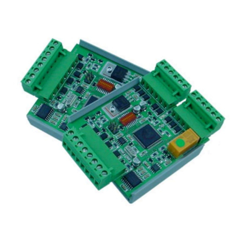
Wired Reader-Extender
Product Manual
Cypress Integration Solutions 30+ Years of Access Control Ingenuity CypressIntegration.com
© 2017 Cypress Computer Systems 1778 Imlay City Road, Lapeer, MI 48446 800-807-2977
2
Specifications
Part Numbers
SPX-7500
UPC 816684003240
RS-485 Reader-Extender (pair of Central and Remote units)
SPX-7500C
UPC 816684001666
RS-485 Reader-Extender (Central unit only)
SPX-7500R
UPC 816684001659
RS-485 Reader-Extender (Remote unit only)
EXP-2000
UPC 816684003233
Optional expansion modules to connect additional readers
Physical
SPX-7500 Enclosure
4.50” x 3.07” x 2.02” / 0.445 lbs
EXP-2000 Enclosure
4.50” x 2.83” x 0.94” / 0.3 lbs
Environmental
Storage Temperature
-40˚C to 100˚C
Operating Temperature
-30˚C to 60˚C
Electrical
Central and Remote Supply Voltage
8-16Vdc Current 300mA
Relays
Max Switching
220Vdc 30W (resistive) 1A / 250Vac 37.5VA 1A
Running Spec with load
30Vdc 1A (resistive) / 125 Vac 0.3A (resistive), 1x10⁵ operations @ 20˚C
Range and
Cable
Requirements
Up to 10,000 ft.
22 AWG, Shielded, Twisted Pair
Additional
Features
SPX-7500 includes complete solution with Central (panel) and Remote (reader/gate/door) interface
Onboard relays to control door/gate
Auxiliary I/O available for LED signal and door/gate/panel status signal
Status LED and Supervision Relay (default off) monitor wireless connection status
The Suprex®RS-485 SPX-7500 series makes it possible to install card readers far from the access control panel, by
providing a two wire RS-485 link between the door or gate readers, and most manufacturers’ panels. The Suprex
includes both a Remote (door/gate) unit and a Central (AC Panel) unit. Optional repeaters and extenders are also
available. The SPX-7500 series devices are compatible with the EXP-2000 expansion modules.
Cypress Suprex®RS-485 Series - SPX-7500 Overview
3
Table of Contents
Topic
Page
Overview and Specifications
2
Physical Dimensions and Mounting Hole Locations
4
Central and Remote Pin Layout
5
Setup and Pre-Installation
6
Indicators and Operating Modes
7
Common Configuration and Run Mode Settings
8
DIP Switch Map
9
Quick Reference for Typical Connections
10
Troubleshooting
11
Accessory I/O
I/O Overview
12
Central Relay Inputs
13
Relay 1 & 2 I/O
14
Remote Relay Inputs
15
Relay 3 & 4 I/O
16
Using the Remote Digital Relay Inputs
17
LED I/O
18
Aux I/O
19
Application Note on Using Supervised Contacts
20
EXP-2000
Expansion Modules
Overview and Operation
21
Central EXP Wiring Diagram
22
Remote EXP Wiring Diagram
23
Cypress Suprex®RS-485 Series - Table of Contents
4
Cypress Suprex®RS-485 Series - Physical Dimensions and Mounting Hole Locations
All dimensions are listed in inches.
EXP Enclosure
ø 0.120 X 4
4.125"
2.890"
3.155"
2.121"
2.364"
EXP-2000
ø 0.120 X 4
3.065"
2.770"
4.0625"
2.660"
2.940"
SPX-5631 /
SPX-5641 /
RPT-5651
SPX-7500
Enclosure
5
Cypress Suprex®RS-485 Series - Central and Remote Pin Layout
8-16VDC Input
Ground
EXP(+)
EXP(-)
+5VDC Output
Prog Res 2
Prog Res 1
LED Input
D1 / Data Out
D0 / Clock Out
Relay 4 N.O.
Relay 4 COM
Relay 4 N.C.
Relay 3 N.O.
Relay 3 COM
Relay 3 N.C.
Ground
Aux Output
Relay 2 Input
Relay 1 Input
8-16VDC Input
Ground
EXP(+)
EXP(-)
+5VDC Output
Relay 4 Input
Relay 3 Input
LED Output
D1 / Data Output
D0 / Clock Input
Relay 2 N.O.
Relay 2 COM
Relay 2 N.C.
Relay 1 N.O.
Relay 1 COM
Relay 1 N.C.
Ground
Aux Input
Not Used
Not Used
SPX-7500 Central
SPX-7500 Remote
6
Cypress Suprex® RS-485 Series - Setup and Pre-installation
Final Field Installation Checklist:
•The Central unit and access control panel should have a common ground.
•The Remote unit and card reader should have a common ground.
•The RS-485 connection between the Central and Remote unit is straight through, and not reversed.
Unpacking:
Remove Central and Remote units from from the packaging material and check interior for any shipping damage. Inventory
any included parts (depending on model) such as terminal connectors.
Bench Testing:
Before installing the units in the field they should be assembled and tested at a convenient bench top location. This will
make it easier to verify / change settings and check operation when both units are visible at the same time.
It is also a chance to become familiar with the system if this is the first time using the Suprex system. It is much more
difficult to set up and test the units when they are several thousand feet apart.
Both units will need to be connected with two conductors (see image below) and each will need to be powered by a suitable
power supply. For testing purposes, the units can share the same power supply.
Basic Bench Test:
During initial setup, refer to the Run / Configuration mode settings (pgs 7-9).
1. Connect a suitable power supply to both units. Each unit should be provided with 8 - 16 Volts dc and approx 300mA.
Units should be separated by a minimum of 24 inches.
2. Apply power. After about a 1-2 second delay both units Diagnostic LED should be flashing green. The supervision relay
(Relay 3) activates when the units are communicating. Note: Supervision relay is disabled by default (see pgs. 7-9).
3. Touch a jumper wire from the Ground connection to the Relay 1 input on the Central unit. Relay 1 on the Remote unit
should activate with an audible click.
4. Units are shipped from the factory set for the Wiegand data format. If a different format is required, set the DIP switch to
the required reader and panel format (see pgs. 7-9)
5. If a reader & panel are accessible, connect the reader to the Remote unit & the Central unit to the panel to verify card
reads are accepted by the access control system. If troubleshooting is necessary, it is easier with units in close proximity.
6. Once these steps are completed, the units are ready for installation at their permanent locations.
7
LED DIAGNOSTIC INDICATOR
The LED Diagnostic indicator provides information on the operational status of the unit.
If the units are not communicating, viewing the diagnostic indicator LEDs may help to determine the
nature of the problem. See also Troubleshooting, page 13.
•If Central or Remote diagnostic LED is not illuminated:
If the LED(s) are not illuminated on the unit(s), the unit is not powered or there is an electrical problem.
When power is properly applied, the Diagnostic LEDs will be illuminated to show a status below:
•If the Central and Remote unit LEDs are flashing green:
When power is properly applied, and there is communication between the Central and the Remote, the
Central and Remote unit LEDs will flash green after every polling cycle. The speed will depend on how
many expansion units are connected (about 1 flash per second with 7 EXPs).
•If the Central or Remote unit LED alternates between green/red:
There is no communication with the partner unit.
•If the Central or Remote unit LEDs are solid green:
If the unit is in Configuration Mode, the settings have been successfully applied, it is safe to power
cycle the unit and switch back to Run Mode. If the unit is in Run Mode, one of the EXPs is not
communicating properly. Check that all connected EXPs are powered and properly connected. (For
details on setting Configuration Mode, see pgs. 7-9.)
OPERATING MODES
Wired Suprex products have 3 operating modes: Run Mode, Configuration Mode, and Test Mode.
•Run Mode: The units are factory-shipped in Run Mode. Run Mode is used during field operation of units.
Run Mode allows changing of common settings without the need to power-cycle the units. Factory-set
defaults can be changed. Default settings:
•Units are set to operate as 1 Remote and 1 Central unit
•Supervision relay is disabled
•Pullup resistors are disabled
•Number of EXP Expansion Modules is set to 0
•Configuration Mode: Switch to Configuration Mode to change the link type and interface type. Default
settings:
•Default interface type is Wiegand
•Link type is pre-set based on the Suprex model
•Test Mode: Test Mode is used for troubleshooting the reader/panel connection to the Remote/Central
unit. In Test Mode, DIP Switches 3-8 operate as if in Run Mode. Either a single unit or both units can be
set to Test Mode; the Remote and Central units retain all their normal functionality in addition to the
following functions:
•In Test Mode, the Central unit outputs a test card read in the selected interface type every few
seconds
•In Test Mode, the Remote unit briefly triggers Relay 2 when detecting data of the selected interface
type
Cypress Suprex® RS-485 Series - Indicators and Operating Modes
8
Test Mode Select
Turn DIP switch 2 on for Remote &/or Central
Default: Standard Wiegand
Turn on DIP switch 8 on both units
Keypad (Wiegand/No Filter)
Turn on DIP switch 7 on both units
F/2F (Unsupervised)
Turn on DIP switches 6, 7, 8 on both units
Strobed Rising Edge (MR-5)
Turn on DIP switches 7 and 8 on both units
Strobed Rising Edge (Dorado 644)
Turn on DIP switch 6 on both units
Strobed Rising (MagTek)
Turn on DIP switches 6 and 8 on both units
Strobed Falling Edge
Turn on DIP switches 6 and 7 on both units
Configuration Mode settings
Standard Wiegand interface is the default setting. To use with non-Wiegand interface:
a) Power off both Suprex units.
b) Turn on DIP switch 1 on both units.
c) Set DIP switches as described below for appropriate interface:
d) Power on both Suprex units. Status LED should be solid green.
e) Power off both Suprex units; return DIP switch 1 to off position on both units to select Run
Mode settings. When switching to Run Mode, always reselect Run Mode settings.
Central / Remote Select
Turn DIP switch 3 on for Central Mode /
turn off for Remote Mode
Remote Digital/Analog Relay Select
Turn Remote Unit's DIP switch 2 on for digital
input / off for analog input
Supervision Relay (Relay 3, Central Unit)
Turn Central Unit's DIP switch 4 on for supervision
relay / off for normal relay
Supervision Relay (Relay 1, Remote Unit)
Turn Remote Unit's DIP switch 4 on for supervision
relay / off for normal relay
Pullup Resistor Select
Turn on DIP switch 5 to enable pullup resistors / off
to disable [applicable units)
EXP Select (for no EXP)
Turn off DIP switches, 6, 7, and 8 on both units
EXP Select (for 1EXP)
Turn on DIP switch 8 on both units
EXP Select (for 2EXPs)
Turn on DIP switch 7 on both units
EXP Select (for 3-7 EXPs)
See pg. 9
Run Mode settings
Select Run Mode settings as described below, then power on both Suprex units to begin operating
in Run Mode.
Cypress Suprex® RS-485 Series - Common Configuration and Run Mode Settings
Test Mode setting
See page 13 to troubleshoot using Test Mode.
9
Cypress Suprex® RS-485 Series - SPX-7500 DIP Switch Map
Run Mode
12345678
Configuration Mode Select
Remote Relay Mode Select
Central / Remote Select
Supervision Relay Select
Pullup Resistor Select
# of EXP-2000s
Configuration Mode
12345678
Configuration Mode Select
Not Used
Link Type Select
Interface Type Select
Supervision Relay SelectSupervision Relay Select
Test Mode
12345678
Test Mode Select
Central / Remote Select
Supervision Relay Select
Pullup Resistor Select
Interface Type Select
NOTE - 0 = OFF - 1 = ON
Configuration Mode Select - ON = Configuration Mode - OFF = Run Mode
Remote Relay Mode Select - ON = Digital Input - OFF = Analog Input
Central / Remote Select - ON = Central - OFF = Remote
Supervision Relay Select - ON = Enable Supervision Relay - OFF = Disable Supervision Relay
Pullup Resistor Select - ON = Enable Pullup Resistor - OFF = Disable Pullup Resistor
Test Mode Select - DIP Switches 1 & 2 ON = Test Mode
- The DIP Switch selections in Run Mode and Test Mode are ACTIVE, meaning that they can be changed on
the fly without power cycling the unit.
- The DIP Switch selections in Configuration Mode are NOT ACTIVE. This means to set Configuration Mode
setting the unit will need to be powered off, turn DIP 1 on and other Configuration DIP Switches as needed,
power the unit on and the Status LED will be solid green. The solid green LED means the settings have been
set. Power the unit off and return the DIP Switches to the Run Mode positions.
- When using the Remote unit with digital relay inputs the relays are controlled by the "not used" pins on the 10
pin header. Connect the outside "not used" pin to "Ground" to trigger Relay 3. Connect the inside "not used" pin
to "Ground" to trigger Relay 4.
- When using the Remote unit with analog relay inputs the relays are controlled by the "Relay 3 in" and "Relay 4
in" pins. Connect "Relay 3 in" to "Ground" to trigger Relay 3. Connect "Relay 4 in" to "Ground" to trigger Relay4.
# of EXP-2000 Pairs
0 0 0 - None
0 0 1 - 1 Pair
0 1 0 - 2 Pairs
0 1 1 - 3 Pairs
1 0 0 - 4 Pairs
1 0 1 - 5 Pairs
1 1 0 - 6 Pairs
1 1 1 - 7 Pairs
6 7 8 - (Run Mode)
Link Type Select
0
0 0 - No Change
1 0 0 - RS485
3 4 5 - (Config Mode)
Interface Type Select
0 0 0 - No Change
0 0 1 - Wiegand
0 1 0 - Wiegand No Filter
0 1 1 - Strobed Rising (MR5)
1 0 0 - Strobed Rising (Dorado 644)
1 0 1 - Strobed Rising (Mag-Tek)
1 1 0 - Strobed Falling
1 1 1 - Unsupervised F/2F
6 7 8 - (Config and Test Mode)
-The Remote Relay Mode Select (Dip Switch 2 in Run Mode) is only used on the Central unit, and has no
functionality on the Remote unit.
10
Cypress Suprex® RS-485 Series - Quick Reference For Typical Connections
In this wiring example, the door strike follows a dry contact input from the access control panel. See page 15 for
other strike control options.
Ground
LED Out
Data1
Data 0
N.O.
COM
Access
Control
Panel
DC Power
Supply
Power
Ground
+8 to +16 VDC
Ground
exp(+)
exp(-)
+5V Out
P R 4
P R 3
LED In
D1/Data Out
D0/Clock Out
Relay 4 N.O.
Relay 4 Com
Relay 4 N.C.
Relay 3 N.O.
Relay 3 Com
Relay 3 N.C.
Ground
Aux Output
Relay 2 Input
Relay 1 Input
Door
Strike
Output
Card
Reader
Power
Ground
LED IN
Data 1
Data 0
DC Power
Supply
Power
Ground
+8 to +16 VDC
Ground
exp(+)
exp(-)
+5V Out
Relay 4 Input
Relay 3 Input
LED Out
D1/Data In
D0/Clock In
Relay 2 N.O.
Relay 2 Com
Relay 2 N.C.
Relay 1 N.O.
Relay 1 Com
Relay 1 N.C.
Ground
Aux Input
Not Used
Not Used
SPX-7500 Remote
SPX-7500 Central
11
No Communication
When the Central and/or Remote unit is not communicating with its partner, the status LED will flash green/red. To
troubleshoot communication issues, check the following:
•Power:
•Both units must be powered.
•Ensure proper power requirements are met: Unregulated Input 8 to 16Vdc @ 300mA max.
•Installation:
•Ensure the RS-485 connection between the Central and Remote unit is straight through, not reversed.
•Ensure the two conductors are not broken. This can be tested by twisting the two conductors together at
one end and testing continuity between the two conductors at the other end. If there is continuity
between the two conductors then the cable is good.
•Ensure the Central and Remote unit are connected with the proper RS-485 port. The RS-485 port on the
8 pin header is for the EXP-2000 expansion modules. The RS-485 port for communication between the
Central and Remote is on the 2 pin header located on the same side as the 10 pin header.
•Ensure the cable being used for connection between the Central and Remote is the proper type of cable
for the distance between the Central and Remote locations.
•Configuration:
•Ensure both Suprex units are set to the correct link type (see Configuration Mode, pgs. 7-9).
•Ensure Suprex units are properly configured as a Central and Remote pair (see pgs. 25-26).
No Data / Invalid Data
If the access control panel is not receiving valid data, check the following:
•Basic Equipment Check:
•Ensure the reader and the access control panel data port are functional by directly connecting the reader to the
data port and passing card data.
•Check Suprex circuit boards for any signs of visual damage, such as burnt traces, burnt components, or
browning of the PCB; these usually indicate misapplied power.
•Wiring:
•Ensure there is a common ground between the Remote unit and the card reader.
•Ensure there is a common ground between the Central unit and the access control panel.
•Ensure Wiegand data wires are correctly connected and not reversed.
•Configuration:
•Ensure both Suprex units are set to the correct interface type (see Configuration Mode, pgs. 7-9).
•Ensure the access control panel is properly configured for the selected data format.
•Data Voltage: For a Wiegand connection, ensure Data 0 and Data 1 pins on Central and Remote units are at 5V
relative to ground. The data pins can be as low as 4.4V before failing. If any Wiegand data pin is less than 4.4V, it is
necessary to identify which device is pulling down the voltage.
•Disconnect the Suprex from the reader/panel.
•Maintain power on the Suprex and the reader/panel.
•Independently measure the voltages of the Wiegand data pins of the Suprex, and of the reader/panel. If one or
both devices have 4.3V or less, try enabling the pullup resistors on the Suprex by turning on DIP switch 5.
•If internal pullup resistors do not work, try external pullup resistors (through-hole resistor 500ohms - 2Kohms). To
install external pullup resistors, place one end of the through-hole resistor into the +5Vdc pin on the Suprex unit;
place the other end in the low-voltage Wiegand data pin (see pg. 5).
Cypress Suprex® RS-485 Series - Troubleshooting
12
INPUT
OUTPUT
Relay 1 Input (C)
Relay 1 COM, Relay 1 N.C., Relay 1 N.O. (R)
Relay 2 Input (C)
Relay 2 COM, Relay 2 N.C., Relay 2 N.O. (R)
Relay 3 Input (R)
Relay 3 COM, Relay 3 N.C., Relay 3 N.O. (C)
Relay 4 Input (R)
Relay 4 COM, Relay 4 N.C., Relay 4 N.O. (C)
LED Input (C)
LED Output (R)
Aux Input (R)
Aux Output (C)
The Cypress SPX-7500 provides additional data channels to support access control hardware such as door strikes,
tamper alarms, request to exit status, etc. These signals are sent to and from the Central and Remote units without the
need to run additional wiring. We refer to these data channels as Accessory I/O. Accessory I/O data channels include
Relay 1, Relay 2, Relay 3, Relay 4, LED, and AUX. Refer to the following pages (14-21) for details of each Accessory I/O
operation and connection. Below is a table of the Accessory I/O pairs.
Relay I/O
The Relay I/O use active low inputs. When the Relay Inputs are floating (nothing connected) the inputs are set at 5V and
the corresponding Relay Outputs will have continuity between COM and N.C. When the Relay Input is set to 0Volts
(Ground) the input will activate the corresponding Relay Output. The Relay Outputs will have continuity between COM
and N.O. when the relay is activated and will hold this state for as long as the Relay Input is set to 0Volts. The Relay
Inputs can be tested by making a jumper connection to ground and monitoring the change in continuity of the Relay
Outputs.
Relay 3 functions as an Supervision relay when DIP switch 4 is on in Run Mode; a Supervision relay monitors the
condition of the communication link between the Central and Remote units. While in Supervision mode, Relay 3 is
activated when the communication link between the Central and Remote is established and functioning. Relay 3 will
deactivate (alarm condition) when either the Relay 3 Input on the remote is active (pulled low) OR the Remote unit is
unable to communicate with the Central unit (see Application note, pg. 20).
LED and AUX I/O
The LED and AUX I/O use active low inputs. When the inputs are floating (nothing connected) the associated output will
be set to a high level (5V). When the input is set to 0Volts (Ground) the input will activate its associated output. All
Accessory outputs are Open Collector type and will switch to Ground when activated and will hold this state as long as
the input is set to 0Volts. Each input will have an associated output. Inputs can be tested by making a jumper connection
to ground and monitoring the associated output.
Cypress Suprex® RS-485 Series - Accessory I/O - Overview
Accessory I/O Pairs
(C) or (R) denotes the Central unit or Remote unit board where the pin is located.
13
To activate the relay on the Remote unit, connect as shown below. These connections can be used to allow the Remote
relay to operate a DOOR STRIKE, GATE, or other locking hardware. The diagram below shows two methods of
triggering the relays. The first method uses a dry contact to trigger the relay. The second method shows the LED signal
triggering the LEDS.
Relays 1 and 2 are available for accessory outputs at the Remote end. Either relay can be used to provide the Door
Strike or Gate Activation function. This example uses Relay 1. The Relay Input pin is normally high (5V). When the
Relay Input pin is pulled low (0V) the corresponding relay on the Remote unit will be activated. When the relay is
activated, the Relay Output pins will change continuity from N.C. and COM to N.O. and COM (not shown in diagram).
Cypress Suprex® RS-485 Series - Accessory I/O - Central Relay Inputs
Relay Wiring Example - Door Strike Follows LED
Relay Input Wiring Example - Door Strike Follows Dry Contact
Ground
LED Out
Data1
Data 0
N.O.
COM
Access
Control
Panel
Ground
LED Out
Data1
Data 0
N.O.
COM
Access
Control
Panel
+8 to +16 VDC
Ground
exp(+)
exp(-)
+5V Out
P R 4
P R 3
LED In
D1/Data Out
D0/Clock Out
Relay 4 N.O.
Relay 4 Com
Relay 4 N.C.
Relay 3 N.O.
Relay 3 Com
Relay 3 N.C.
Ground
Aux Output
Relay 2 Input
Relay 1 Input
+8 to +16 VDC
Ground
exp(+)
exp(-)
+5V Out
P R 4
P R 3
LED In
D1/Data Out
D0/Clock Out
Relay 4 N.O.
Relay 4 Com
Relay 4 N.C.
Relay 3 N.O.
Relay 3 Com
Relay 3 N.C.
Ground
Aux Output
Relay 2 Input
Relay 1 Input
Central
Central
14
Cypress Suprex® RS-485 Series - Accessory I/O - Relay 1 & 2 I/O
Relay 2 I/O Diagram
+8 to +16 VDC
Ground
exp(+)
exp(-)
+5V Out
P R 4
P R 3
LED In
D1/Data Out
D0/Clock Out
Relay 4 N.O.
Relay 4 Com
Relay 4 N.C.
Relay 3 N.O.
Relay 3 Com
Relay 3 N.C.
Ground
Aux Output
Relay 2 Input
Relay 1 Input
Central
+8 to +16 VDC
Ground
exp(+)
exp(-)
+5V Out
Relay 4 Input
Relay 3 Input
LED Out
D1/Data In
D0/Clock In
Relay 2 N.O.
Relay 2 Com
Relay 2 N.C.
Relay 1 N.O.
Relay 1 Com
Relay 1 N.C.
Ground
Aux Input
Not Used
Not Used
Remote
+8 to +16 VDC
Ground
exp(+)
exp(-)
+5V Out
Relay 4 Input
Relay 3 Input
LED Out
D1/Data In
D0/Clock In
Relay 2 N.O.
Relay 2 Com
Relay 2 N.C.
Relay 1 N.O.
Relay 1 Com
Relay 1 N.C.
Ground
Aux Input
Not Used
Not Used
Remote
+8 to +16 VDC
Ground
exp(+)
exp(-)
+5V Out
P R 4
P R 3
LED In
D1/Data Out
D0/Clock Out
Relay 4 N.O.
Relay 4 Com
Relay 4 N.C.
Relay 3 N.O.
Relay 3 Com
Relay 3 N.C.
Ground
Aux Output
Relay 2 Input
Relay 1 Input
Central
Relay 1 I/O Diagram
+8 to +16 VDC
Ground
exp(+)
exp(-)
+5V Out
P R 4
P R 3
LED In
D1/Data Out
D0/Clock Out
Relay 4 N.O.
Relay 4 Com
Relay 4 N.C.
Relay 3 N.O.
Relay 3 Com
Relay 3 N.C.
Ground
Aux Output
Relay 2 Input
Relay 1 Input
Central
+8 to +16 VDC
Ground
exp(+)
exp(-)
+5V Out
Relay 4 Input
Relay 3 Input
LED Out
D1/Data In
D0/Clock In
Relay 2 N.O.
Relay 2 Com
Relay 2 N.C.
Relay 1 N.O.
Relay 1 Com
Relay 1 N.C.
Ground
Aux Input
Not Used
Not Used
Remote
+8 to +16 VDC
Ground
exp(+)
exp(-)
+5V Out
P R 4
P R 3
LED In
D1/Data Out
D0/Clock Out
Relay 4 N.O.
Relay 4 Com
Relay 4 N.C.
Relay 3 N.O.
Relay 3 Com
Relay 3 N.C.
Ground
Aux Output
Relay 2 Input
Relay 1 Input
Central
+8 to +16 VDC
Ground
exp(+)
exp(-)
+5V Out
Relay 4 Input
Relay 3 Input
LED Out
D1/Data In
D0/Clock In
Relay 2 N.O.
Relay 2 Com
Relay 2 N.C.
Relay 1 N.O.
Relay 1 Com
Relay 1 N.C.
Ground
Aux Input
Not Used
Not Used
Remote
The diagram to the right
shows how the state of the
the Relay 2 Outputs
change the as Relay 2
Input is set to 0Volts
(connected to Ground)
using a jumper connection.
The left side shows that
when Relay 2 Input is not
set to 0Volts, Relay 2
COM and Relay 2 N.C
have continuity. The right
side shows that when
Relay 2 Input is set to
0Volts, Relay 2 COM and
Relay 2 N.O. have
continuity.
The diagram to the right
shows how the state of the
the Relay 1 Outputs
change the as Relay 1
Input is set to 0Volts
(connected to Ground)
using a jumper connection.
The left side shows that
when Relay 1 Input is not
set to 0Volts, Relay 1
COM and Relay 1 N.C
have continuity. The right
side shows that when
Relay 1 Input is set to
0Volts, Relay 1 COM and
Relay 1 N.O. have
continuity.
15
Cypress Suprex® RS-485 Series - Accessory I/O - Remote Relay Inputs
To activate the relay on the Central unit, connect as shown below. These connections can be used to operate a REX
switch or other signals that need to go to the access panel.
Relays 3 and 4 are available for accessory outputs at the Central end. Either Relay 3 or Relay 4 can be used. This
example uses Relay 4. The Relay Input pin is normally high (5V). When the Relay Input pin is pulled low (0V) the
corresponding relay on the Remote unit will be activated. When the relay is activated, the relay output pins will change
continuity from N.C. and COM to N.O. and COM (not shown in diagram).
Relay 3 can used to send signals to the access panel while Supervision mode is active, but it is important to remember
that the outputs will be reversed. When Supervision mode is active and the Relay 3 Input pin is normal (5V) the relay
output pins will have continuity between N.O. and COM. When Supervision mode is active and the Relay 3 Input pin is
active (0V) the relay output pins will have continuity between N.C. and COM.
Relay Wiring Example - REX Switch
+8 to +16 VDC
Ground
exp(+)
exp(-)
+5V Out
Relay 4 Input
Relay 3 Input
LED Out
D1/Data In
D0/Clock In
Relay 2 N.O.
Relay 2 Com
Relay 2 N.C.
Relay 1 N.O.
Relay 1 Com
Relay 1 N.C.
Ground
Aux Input
Not Used
Not Used
Remote
16
Cypress Suprex® RS-485 Series - Accessory I/O - Relay 3 & 4 I/O
Relay 4 I/O Diagram
+8 to +16 VDC
Ground
exp(+)
exp(-)
+5V Out
P R 4
P R 3
LED In
D1/Data Out
D0/Clock Out
Relay 4 N.O.
Relay 4 Com
Relay 4 N.C.
Relay 3 N.O.
Relay 3 Com
Relay 3 N.C.
Ground
Aux Output
Relay 2 Input
Relay 1 Input
Central
+8 to +16 VDC
Ground
exp(+)
exp(-)
+5V Out
P R 4
P R 3
LED In
D1/Data Out
D0/Clock Out
Relay 4 N.O.
Relay 4 Com
Relay 4 N.C.
Relay 3 N.O.
Relay 3 Com
Relay 3 N.C.
Ground
Aux Output
Relay 2 Input
Relay 1 Input
Central
+8 to +16 VDC
Ground
exp(+)
exp(-)
+5V Out
Relay 4 Input
Relay 3 Input
LED Out
D1/Data In
D0/Clock In
Relay 2 N.O.
Relay 2 Com
Relay 2 N.C.
Relay 1 N.O.
Relay 1 Com
Relay 1 N.C.
Ground
Aux Input
Not Used
Not Used
Remote
+8 to +16 VDC
Ground
exp(+)
exp(-)
+5V Out
Relay 4 Input
Relay 3 Input
LED Out
D1/Data In
D0/Clock In
Relay 2 N.O.
Relay 2 Com
Relay 2 N.C.
Relay 1 N.O.
Relay 1 Com
Relay 1 N.C.
Ground
Aux Input
Not Used
Not Used
Remote
Relay 3 I/O Diagram
+8 to +16 VDC
Ground
exp(+)
exp(-)
+5V Out
P R 4
P R 3
LED In
D1/Data Out
D0/Clock Out
Relay 4 N.O.
Relay 4 Com
Relay 4 N.C.
Relay 3 N.O.
Relay 3 Com
Relay 3 N.C.
Ground
Aux Output
Relay 2 Input
Relay 1 Input
Central
+8 to +16 VDC
Ground
exp(+)
exp(-)
+5V Out
P R 4
P R 3
LED In
D1/Data Out
D0/Clock Out
Relay 4 N.O.
Relay 4 Com
Relay 4 N.C.
Relay 3 N.O.
Relay 3 Com
Relay 3 N.C.
Ground
Aux Output
Relay 2 Input
Relay 1 Input
Central
+8 to +16 VDC
Ground
exp(+)
exp(-)
+5V Out
Relay 4 Input
Relay 3 Input
LED Out
D1/Data In
D0/Clock In
Relay 2 N.O.
Relay 2 Com
Relay 2 N.C.
Relay 1 N.O.
Relay 1 Com
Relay 1 N.C.
Ground
Aux Input
Not Used
Not Used
Remote
+8 to +16 VDC
Ground
exp(+)
exp(-)
+5V Out
Relay 4 Input
Relay 3 Input
LED Out
D1/Data In
D0/Clock In
Relay 2 N.O.
Relay 2 Com
Relay 2 N.C.
Relay 1 N.O.
Relay 1 Com
Relay 1 N.C.
Ground
Aux Input
Not Used
Not Used
Remote
The diagram to the right
shows how the state of the
the Relay 3 Outputs
change the as Relay 3
Input is set to 0Volts
(connected to Ground)
using a jumper connection.
The left side shows that
when Relay 3 Input is not
set to 0Volts, Relay 3
COM and Relay 3 N.C
have continuity. The right
side shows that when
Relay 3 Input is set to
0Volts, Relay 3 COM and
Relay 3 N.O. have
continuity.
The diagram to the right
shows how the state of the
the Relay 4 Outputs
change the as Relay 4
Input is set to 0Volts
(connected to Ground)
using a jumper connection.
The left side shows that
when Relay 4 Input is not
set to 0Volts, Relay 4
COM and Relay 1 N.C
have continuity. The right
side shows that when
Relay 4 Input is set to
0Volts, Relay 4 COM and
Relay 4 N.O. have
continuity.
17
Cypress Suprex® RS-485 Series - Using the Remote Digital Relay Inputs
This section applies only to the Remote unit, as the Central unit has only digital relay inputs. DIP
switch 2 controls whether the Remote unit uses the analog relay inputs or the digital relay inputs. By
default, DIP switch 2 is off and the Remote unit is set to use the analog relay inputs. When DIP switch
2 is in the ON position, the Remote unit is set to use the digital relay inputs. The digital relay inputs
function in the same way the analog inputs on the Remote unit function. The digital relay inputs simply
need to be connected to ground for the corresponding relay to be activated.
To active the digital relay inputs, only DIP switch 2 on the Central board needs to be enabled. DIP
switch 2 on the Remote board has no function. It may be necessary to power-cycle the Central unit for
the change to take effect.
Note: The digital relay input pins are not the same Relay 3 and Relay 4 input pins labeled on the
Remote unit. Instead, the digital relay input pins use the two “Not Used” pins on the 10 pin header. The
“Not Used” pin on the outside of the board is the new Relay 3 input pin, the other “Not Used” pin is the
new Relay 4 input pin. Use the diagram below as a reference.
For most applications the analog relay inputs are sufficient. But for instances where a significant delay
is noticed in the activation of Relay 3 and Relay 4, the end user should switch to using digital relay
inputs. The digital relay input pins are able to detect a signal change faster than the analog inputs are,
and this may eliminate the delay in the activation of the relay.
Note regarding EXP units: While DIP switch 2 is on and the digital relay input pins are enabled on
the SPX-7500 units, the digital relay inputs are also enabled on any EXP-2000 Remote units that are
connected. The digital relay input pins are on the 12 pin header and are the two “Not Used” pins. The
outside “Not Used” pin is the Relay 3 Input pin and the other “Not Used” pin is the Relay 4 Input pin.
+8 to +16 VDC
Ground
exp(+)
exp(-)
+5V Out
Relay 4 Input
Relay 3 Input
LED Out
D1/Data In
D0/Clock In
Relay 2 N.O.
Relay 2 Com
Relay 2 N.C.
Relay 1 N.O.
Relay 1 Com
Relay 1 N.C.
Ground
Aux Input
Not Used
Not Used
+8 to +16 VDC
Ground
exp(+)
exp(-)
+5V Out
Not Used
Not Used
LED Out
D1/Data In
D0/Clock In
Relay 2 N.O.
Relay 2 Com
Relay 2 N.C.
Relay 1 N.O.
Relay 1 Com
Relay 1 N.C.
Ground
Aux Input
Relay 4 Input
Relay 3 Input
DIP Switch 2 Off
(Analog Inputs)
DIP Switch 2 On
(Digital Inputs)
Analog and Digital Relay Input Pins
Remote Remote
18
Cypress Suprex® RS-485 Series - Accessory I/O - LED I/O
For access control panels with a LED Output signal, the SPX-7500 is able to transmit this signal to the reader with the
LED Input and LED Output pins. The LED In pin is a digital input and the LED Out pin is a digital output. The LED In pin
has two states, 5V (high or normal) and 0V (low or active). The LED Out pin will mirror the state of the LED In pin.
The LED I/O Signal Diagram below shows how this signal is passed through he SPX-7500.
Ground
LED Out
Data1
Data 0
N.O.
COM
Access
Control
Panel
Card
Reader
Power
Ground
LED IN
Data 1
Data 0
LED I/O Signal Diagram
+8 to +16 VDC
Ground
exp(+)
exp(-)
+5V Out
Relay 4 Input
Relay 3 Input
LED Out
D1/Data In
D0/Clock In
Relay 2 N.O.
Relay 2 Com
Relay 2 N.C.
Relay 1 N.O.
Relay 1 Com
Relay 1 N.C.
Ground
Aux Input
Not Used
Not Used
+8 to +16 VDC
Ground
exp(+)
exp(-)
+5V Out
P R 4
P R 3
LED In
D1/Data Out
D0/Clock Out
Relay 4 N.O.
Relay 4 Com
Relay 4 N.C.
Relay 3 N.O.
Relay 3 Com
Relay 3 N.C.
Ground
Aux Output
Relay 2 Input
Relay 1 Input
Central
Remote
19
Cypress Suprex® RS-485 Series - Accessory I/O - AUX I/O
The SPX-7500 has an auxiliary I/O signal going from the reader side to the panel side. The SPX-7500 is able to transmit
this signal to the panel with the AUX Input and AUX Output pins. The AUX In pin is a digital input and the AUX Out pin is a
digital output. The AUX In pin has two states, 5V (high or normal) and 0V (low or active). The AUX Out pin will mirror the
state of the AUX In pin.
The AUX I/O Signal Diagram below shows how this signal is passed through the SPX-7500.
AUX I/O Signal Diagram
Ground
Input
Data1
Data 0
N.O.
COM
Access
Control
Panel
Card
Reader
Power
Ground
Output
Data 1
Data 0
+8 to +16 VDC
Ground
exp(+)
exp(-)
+5V Out
Relay 4 Input
Relay 3 Input
LED Out
D1/Data In
D0/Clock In
Relay 2 N.O.
Relay 2 Com
Relay 2 N.C.
Relay 1 N.O.
Relay 1 Com
Relay 1 N.C.
Ground
Aux Input
Not Used
Not Used
+8 to +16 VDC
Ground
exp(+)
exp(-)
+5V Out
P R 4
P R 3
LED In
D1/Data Out
D0/Clock Out
Relay 4 N.O.
Relay 4 Com
Relay 4 N.C.
Relay 3 N.O.
Relay 3 Com
Relay 3 N.C.
Ground
Aux Output
Relay 2 Input
Relay 1 Input
Central
Remote
20
The following applies to these products: SPX-7500.
This application note describes the connections necessary to convey supervised contact status over a Suprex. The
configurations described in this application note should apply to most panels which utilize supervised contacts. When
connected as described, the Suprex provides a supervised signal to the panel interface by reading the supervised status of
the contacts connected to the Suprex Remote unit.
Theory of operation: The access control panel is looking for a certain value of resistance connected to the supervised
contact terminals. The Suprex Central unit will provide these resistance values locally at the panel so that the correct
supervised status is maintained. At the same time, the Remote unit must maintain supervision of the wires connected to
the relays and switches connected to the remote access point. The contact supervision is provided by the Remote unit.
The Suprex system does this by comparing the value of programming resistor at the Central unit with the resistance seen
at the Remote interface terminals. When there is a difference in the two values, the Relay on the Central unit is activated.
There are two different
examples. One example is
monitoring a normally closed
contact at the Remote unit, and
the other example is monitoring
a normally open contact at the
Remote unit. In the examples
given, a normally closed
contact will require a
programming resistor of 1K and
a normally open contact will
require a programming resistor
of 2K. Other resistor values can
be used, but 1K resistors are
the most common. Other
resistance values will require
different value(s) for the
programming resistor(s).
+8 to +16 VDC
Ground
exp(+)
exp(-)
+5V Out
P R 4
P R 3
LED In
D1/Data Out
D0/Clock Out
Relay 4 N.O.
Relay 4 Com
Relay 4 N.C.
Relay 3 N.O.
Relay 3 Com
Relay 3 N.C.
Ground
Aux Output
Relay 2 Input
Relay 1 Input
+8 to +16 VDC
Ground
exp(+)
exp(-)
+5V Out
Relay 4 Input
Relay 3 Input
LED In
D1/Data In
D0/Clock In
Relay 2 N.O.
Relay 2 Com
Relay 2 N.C.
Relay 1 N.O.
Relay 1 Com
Relay 1 N.C.
Ground
Aux Input
Not Used
Not Used
+8 to +16 VDC
Ground
exp(+)
exp(-)
+5V Out
P R 4
P R 3
LED In
D1/Data Out
D0/Clock Out
Relay 4 N.O.
Relay 4 Com
Relay 4 N.C.
Relay 3 N.O.
Relay 3 Com
Relay 3 N.C.
Ground
Aux Output
Relay 2 Input
Relay 1 Input
Central
Remote
Remote
Central
Normally Closed Contact
Normally Open Contact
1K
1K
Input +
Input -
+8 to +16 VDC
Ground
exp(+)
exp(-)
+5V Out
Relay 4 Input
Relay 3 Input
LED In
D1/Data In
D0/Clock In
Relay 2 N.O.
Relay 2 Com
Relay 2 N.C.
Relay 1 N.O.
Relay 1 Com
Relay 1 N.C.
Ground
Aux Input
Not Used
Not Used
1K
1K
2K
1K
1K
1K
Input -
Input +
Application note on using supervised contacts with the Suprex® RS-485 Series

This manual suits for next models

7

Other Cypress Extender manuals

Cypress Suprex RS-485 User manual

Cypress

Cypress Suprex RS-485 User manual

Cypress DCT-32TX User manual

Cypress

Cypress DCT-32TX User manual

Cypress CLUX-SDI2HC User manual

Cypress

Cypress CLUX-SDI2HC User manual

Cypress Suprex SPX-7200 User manual

Cypress

Cypress Suprex SPX-7200 User manual

Cypress Suprex  SPX-5631 User manual

Cypress

Cypress Suprex SPX-5631 User manual

Cypress Suprex SPX-7400 Series User manual

Cypress

Cypress Suprex SPX-7400 Series User manual

Cypress CMDP-13MDPI User manual

Cypress

Cypress CMDP-13MDPI User manual

Cypress SPX-1200 User manual

Cypress

Cypress SPX-1200 User manual

Cypress Suprex SPX-7200 User manual

Cypress

Cypress Suprex SPX-7200 User manual

Cypress Suprex SPX-1300 User manual

Cypress

Cypress Suprex SPX-1300 User manual

Cypress CA-USBHUT User manual

Cypress

Cypress CA-USBHUT User manual

Cypress Suprex SPX-1300 User manual

Cypress

Cypress Suprex SPX-1300 User manual

Cypress PU-515PL-KIT HDBaseT User manual

Cypress

Cypress PU-515PL-KIT HDBaseT User manual

Cypress CIR-12 User manual

Cypress

Cypress CIR-12 User manual

Cypress CLUX-SDI2HC User manual

Cypress

Cypress CLUX-SDI2HC User manual

Cypress Suprex  SPX-5631 User manual

Cypress

Cypress Suprex SPX-5631 User manual

Cypress CY3242-IOXlite User manual

Cypress

Cypress CY3242-IOXlite User manual

Cypress DPX-5500 Series User manual

Cypress

Cypress DPX-5500 Series User manual

Cypress Suprex SPX-5600 Series User manual

Cypress

Cypress Suprex SPX-5600 Series User manual

Cypress Suprex RF SPX-5631R User manual

Cypress

Cypress Suprex RF SPX-5631R User manual

Cypress CIR-03 User manual

Cypress

Cypress CIR-03 User manual

Cypress Suprex WMR-9600MAN User manual

Cypress

Cypress Suprex WMR-9600MAN User manual

Popular Extender manuals by other brands

SC&T UE01 user manual

SC&T

SC&T UE01 user manual

D-Link DHP-701AV Quick installation guide

D-Link

D-Link DHP-701AV Quick installation guide

NETGEAR XAVN2001v1 manual

NETGEAR

NETGEAR XAVN2001v1 manual

RF-Link WAVECOM Sr owner's manual

RF-Link

RF-Link WAVECOM Sr owner's manual

DIPRA SPID'O GC-800I-24H5 Original operating instructions

DIPRA

DIPRA SPID'O GC-800I-24H5 Original operating instructions

Avocent LongView Wireless brochure

Avocent

Avocent LongView Wireless brochure

D-Link AMPLIFI DAP-1525 user manual

D-Link

D-Link AMPLIFI DAP-1525 user manual

Uniclass DX120 Quick installation guide

Uniclass

Uniclass DX120 Quick installation guide

Key Digital KD-X444SP manual

Key Digital

Key Digital KD-X444SP manual

Gefen EXT-DVI-1CAT6 user manual

Gefen

Gefen EXT-DVI-1CAT6 user manual

CLAS OE 5010 manual

CLAS

CLAS OE 5010 manual

Yamaha TX-7 owner's manual

Yamaha

Yamaha TX-7 owner's manual

TP-Link RE360 user guide

TP-Link

TP-Link RE360 user guide

Celabs HX70M instruction manual

Celabs

Celabs HX70M instruction manual

ICON QCon EX G2 user manual

ICON

ICON QCon EX G2 user manual

dji Ronin 4D Video Transmitter user guide

dji

dji Ronin 4D Video Transmitter user guide

Clare Controls HDBaseT CM-BT20-COMPACT-70-TX manual

Clare Controls

Clare Controls HDBaseT CM-BT20-COMPACT-70-TX manual

DVIGear DVI-7380 user guide

DVIGear

DVIGear DVI-7380 user guide

manuals.online logo
manuals.online logoBrands
  • About & Mission
  • Contact us
  • Privacy Policy
  • Terms and Conditions

Copyright 2025 Manuals.Online. All Rights Reserved.