D-Link DPS-520 User manual
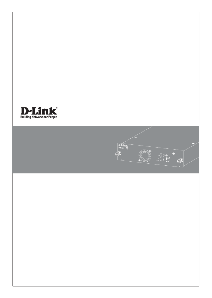
Quick Installation Guide for
Redundant Power System
DPS-520

2
Information in this document is subject to change without notice. Reproduction in any manner whatsoever,
without the written permission of D-Link Corporation, is strictly forbidden.
Trademarks used in this text: D-Link and the D-LINK logo are trademarks of D-Link Corporation; Microsoft and
Windows are registered trademarks of Microsoft Corporation.
Other trademarks and trade names may be used in this document to refer to either the entities claiming the
marks and names or their products. D-Link Corporation disclaims any proprietary interest in trademarks and
trade names other than its own.
© 2020 D-Link Corporation. All rights reserved.
FCC Compliance Statement
This device complies with Part 15 of the FCC Rules. Operation is subject to the following two conditions: (1) This
device may not cause harmful interference, and (2) this device must accept any interference received, including
interference that may cause undesired operation.
D-Link Corporate
17595 Mt. Hermann Street
Fountain Valley, CA 92708
(800) 326-1688
CE Mark Warning
This equipment is compliant with Class A of CISPR 32. In a residential environment, this equipment may cause
radio interference.
Avertissement Concernant la Marque CE
Cet équipement est conforme à la classe A de la norme CISPR 32. Dans un environnement résidentiel, cet
équipement peut provoquer des interférences radio.
VCCI Warning
この装置は、クラスA機器です。この装置を住宅環境で使用すると電波妨害を引き起こすことがありま
す。この場合には使用者が適切な対策を講ずるよう要求されることがあります。 VCCI-A
BSMI Notice
此為甲類資訊技術設備,於居住環境中使用時,可能會造成射頻擾動,在此種情況下,使用者會被要求採
取某些適當的對策。
3
About This Guide
The D-Link DPS-520 is a Redundant Power System (RPS)
provides an aordable, 90 Watt, Power over HDBaseT
(PoH), rack-mountable, RPS solution. This guide provides
step-by-step instructions to setup the RPS and install it to
a switch that supports incoming PoH.
Please note that the model you have purchased may
appear slightly dierent from those shown in the
illustrations. For more detailed information about your
product, its components, making connections, and
technical specications, please refer to the User’s Guide
included with your product.
Introduction
The DPS-520 provides an eective solution when the
internal power supply of a switch in the network fails,
which can result in the shutdown of a single switching
device or an entire network.
With an RPS connected, an integrated detection circuit
continuously monitors the switch’s internal power
supply. In the event of a power interruption, the RPS is
immediately triggered so that the switch and connected
devices can continue providing services. This results in
a more reliable network infrastructure and protects the
network from a single failure of a network device power
supply.
Description
The DPS-520 is an RPS unit features four Gigabit Ethernet
90W PoH ports and one Gigabit Ethernet Management
port (MGMT). It is designed to conform to the power
requirements of the switches being supported.
Using PoH, it connects to a PoH-enabled switch using
a standard Ethernet UTP/STP cable. A standard, three-
pronged AC power cable connects the RPS to the main
power source.
Figure 1 - Front View of the DPS-520
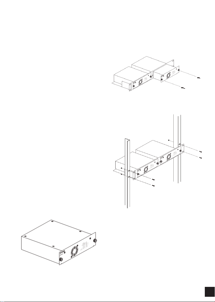
Rack Installation
The DPS-520 can be installed on a desktop or into a
standard switch rack by inserting it into an additional
DPS-800.
The DPS-800 is a standard-size rack mount (1.25U in
height) designed to hold up to two RPS units.
Figure 2 - Installing the DPS-520 into the DPS-800
Figure 3 - Installing the DPS-800 in a standard switch rack
4
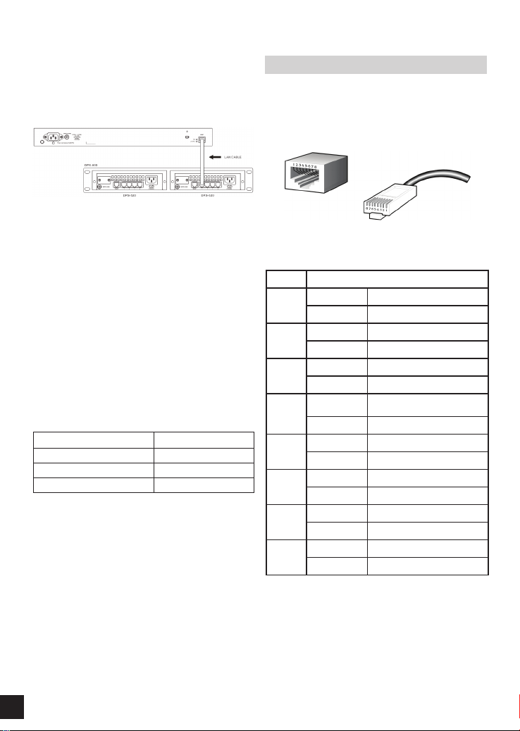
Switch Connection
Only the LAN ports 1 to 4 can supply power to switches.
Insert one end of the DC-powered, PoH, Ethernet cable
into one of the LAN ports on the DPS-520 and insert the
other end into the PoH-capable input port on the switch
(usually the MGMT port).
Figure 4 - Connecting the DPS-520 to a PoH-enabled switch
The MGMT port on the DPS-520 cannot supply power
to a switch and is usually used for the connection to the
management PC.
Power Connection
Connecting AC Power to the RPS Using a standard AC
power cable, connect the RPS to the main AC power
source. A green LED on the front of the RPS will glow to
indicate a successful connection.
Product Specication
Specication DPS-520
AC Input Voltage 100 ~ 240 VAC
AC Input Frequency 50 ~ 60 Hz
Operating Temperature 0 ~ 50 °C
Table 1 - Product Specifications
RPS Cable Pin Assignment
Any standard Category 5e or higher Ethernet cable can
be used to connect the RPS to the switch where the RPS
supplies PoH power to the switch. The following illustrates
the RJ45 PoH receptacle/connector and pin assignments.
Figure 5 - RJ45 PoH Pin Assignment
Pin Description
1Rx A+ Receive data
DC- Feeding power (-) 48 V
2Rx A- Receive data
DC- Feeding power (-) 48 V
3Tx B+ Transmit data
DC+ Feeding power (+) 0 V
4BI C+ Bidirectional data
DC+ Feeding power (+) 0 V
5BI C- Bidirectional data
DC+ Feeding power (+) 0 V
6Tx B- Transmit data
DC+ Feeding power (+) 0 V
7BI D+ Bidirectional data
DC- Feeding power (-) 48 V
8BI D- Bidirectional data
DC- Feeding power (-) 48 V
Table 2 - RJ45 PoH Pin Assignment
5
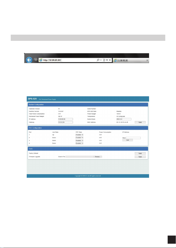
Web User Interface
The Web User Interface (Web UI) provides access to the software features available on the RPS. These features can be
accessed on the LAN ports or the MGMT port using any standard web browser, like Microsoft’s Internet Explorer, Mozilla
Firefox, Google Chrome, or Safari.
Connecting to the Web UI
To access the Web UI, open a standard web browser, enter the IP address of the RPS into the address bar of the browser,
and press the Enter key.
Figure 6 - IP address in Internet Explorer
NOTE: The default IP address of the DPS-520 is 10.90.90.90 (subnet mask 255.0.0.0).
After successfully connecting to the Web UI, the following is displayed:
Figure 7 - Web User Interface (Web UI)
6
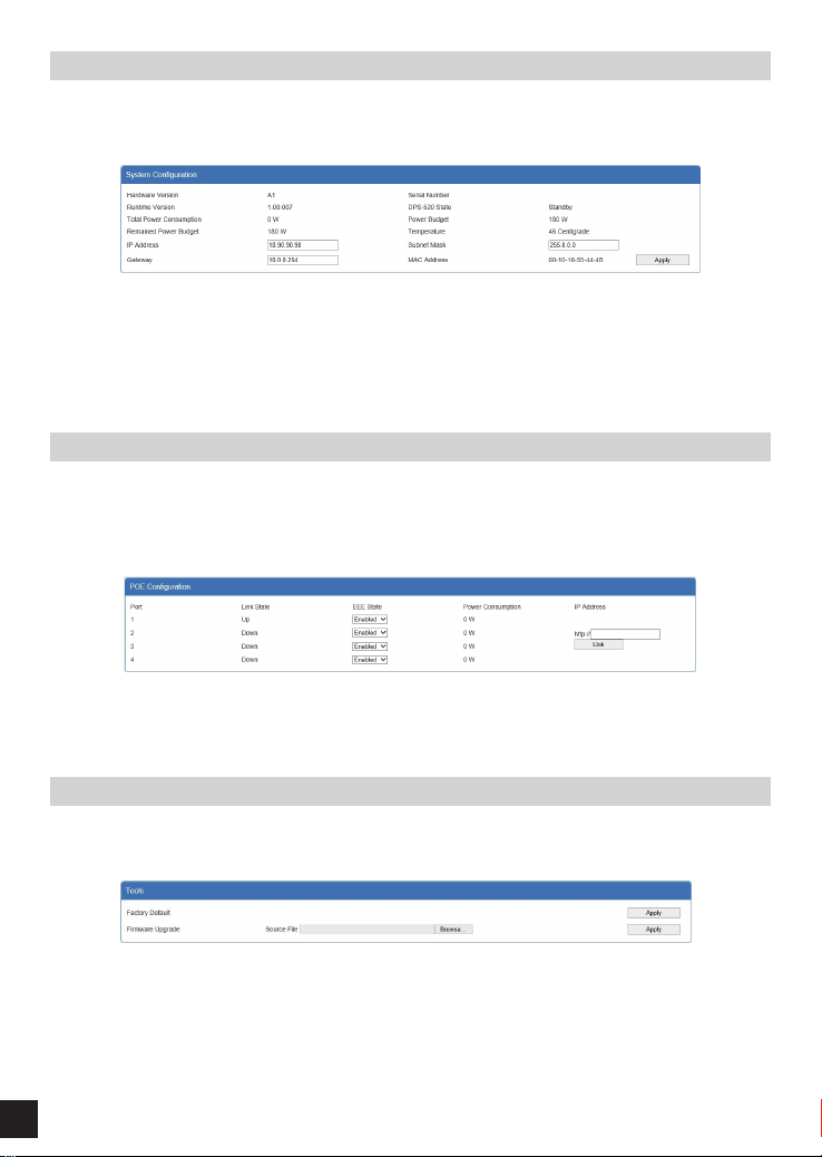
System Conguration
The IP Address, Subnet Mask, and Gateway IP address can be congured here. Click the Apply button to apply the
changes.
Figure 8 - System Configuration
Additional system information is displayed in this section like Hardware Version, Serial Number, Runtime Version,
DPS-520 State, Total Power Consumption, Power Budget, Remaining Power Budget,Temperature and the MAC
Address of the RPS.
PoE Information
The EEE State and the Link IP address can be congured here. Enter the IP Address of a device, connected to the RPS,
and click the Link button to open a new tab in the web browser to initiate an HTTP connection to the specied IP
address.
Figure 9 - PoE Information
Additional PoE information is displayed in this section like Port number, Link Status, and Power Consumption.
Tools
Click the Apply button, next Factory Default, to reset the software on the RPS back to the factory default conguration.
Figure 10 - Tools
Firmware Upgrade: To upgrade the rmware, click the Browse button, navigate to the new rmware le, and click the
Apply button to upgrade the rmware on the RPS.
Important: The DPS-520 needs to be restarted for the software changes to take eect. To restart the DPS-520, the AC
power cord needs to be removed and then re-inserted into the AC power port on the back panel.

7
Additional Information
Additional help is available through our oces listed at
the back of the user manual or online. To nd out more
about D-Link products or marketing information, please
visit the website: http://www.dlink.com
Warranty Information
The D-Link Limited Lifetime Warranty information is
available at http://warranty.dlink.com/
Safety Instructions
The following general safety guidelines are provided to
help ensure your own personal safety and protect your
product from potential damage. Remember to consult
the product user instructions for more details.
• Static electricity can be harmful to electronic
components. Discharge static electricity from your body
(i.e. touching grounded bare metal) before touching the
product.
• Do not attempt to service the product and never
disassemble the product. For some products with a
user replaceable battery, please read and follow the
instructions in the user manual.
• Do not spill food or liquid on your product and never
push any objects into the openings of your product.
• Do not use this product near water, areas with
high humidity, or condensation unless the product is
specically rated for outdoor application.
• Keep the product away from radiators and other heat
sources.
• Always unplug the product from mains power before
cleaning and use a dry lint free cloth only.
European Community
Declaration of Conformity
D-Link hereby declares that this product, accessories, and
software are in compliance with directive 2014/53/EU.
More information about EU Declaration of Conformity
please visit www.dlink.com/cedoc

Ver.1.00(WW)_90x130 2020/08/11 6DPS520Q..01G
Other manuals for DPS-520
1
Table of contents
Other D-Link Power Supply manuals

D-Link
D-Link DIS-PWR180AC/RU User manual

D-Link
D-Link DIS-PWR40AC/RU User manual

D-Link
D-Link DPS-200A User manual

D-Link
D-Link mydlink DSP-W215 User manual

D-Link
D-Link DCS-80-5 User manual

D-Link
D-Link DPS-510 User manual

D-Link
D-Link DMC-1001 - Power Supply - hot-plug User manual

D-Link
D-Link DGS-6604-SK User manual

D-Link
D-Link mydlink DSP-W215 User manual

D-Link
D-Link DMC-1001 - Power Supply - hot-plug User manual


