D-Link DPS-300 User manual


Introduction
A redundant power supply provides a low-cost, simple
solution to the equally simple yet vexing problem of internal
power supply failure, which can result in the shutdown of a
single switching device or an entire network.
With a redundant power supply connected, an integrated
detection circuit continuously monitors the switch’s internal
power supply. In the event of a power interruption, the
redundant power supply is immediately triggered so that the
switch and connected devices can continue providing
service.
This results in a more reliable network infrastructure and
protects the network from a single failure of a network
device power supply.
Description
The DPS-200, DPS-300, DPS-500, DPS-500DC, DPS-600
and DPS-700 are redundant power supply units designed to
conform to the wattage requirements of the switches being
supported. DPS-200 operates at 60 watts; DPS-300
operates at 90 watts, DPS-500/500DC at 140 watts, DPS-
600 at 500watts, and the DPS-700 at 589 watts.
The DPS-200, DPS-300, DPS-500, DPS-500DC, and DPS-
600 can connect to the master switch using a 14-pin DC
power cable. Similarly, the DPS-700 uses a 22-pin DC
power cable. A standard, three-pronged AC power cable
connects the redundant power supply to the main power
source.
Single RPS (DPS-200/DPS-300
/DPS-500/DPS-500DC)
Single RPS (DPS-
600/700)
14-pin DC power cable
22-pin DC power cable
Installation of the RPS
The single RPS DPS-200, 300, 500, and 500DC can be
installed to the standard rack via the RPS rack DPS-800
and DPS-900. DPS-900 is a standard-size rack mount (5U
in height) designed to hold up to 8 redundant power
supplies. The DPS-800 is also a standard-size rack mount
(1.25U in height) designed to hold up to 2 redundant power
supplies. Installed RPS units can be DPS-200s, DPS-300s,
DPS-500s, DPS-500DCs, or a combination of the above.
NOTE: The DPS-500DC can only be
inserted into a DPS-800
Installing a DPS-
600/700 in a standard
electronics rack
Inserting a single
RPS into a DPS-800
RPS rack
Installing a DPS-800 in a
standard electronics rack
Inserting a single
RPS into a DPS-900
RPS rack
Installing a DPS-900 in a
standard electronics
rack

Switch Connection
Caution: The redundant power supply should
be disconnected from its power source before
connecting to the switch. Directly connecting
a powered RPS to the switch may cause
damage to the switch’s internal power supply.
Insert one end of the DC power cable into the receptacle on
the switch and the other end into the redundant power
supply.
Connecting a DPS-600 to a switch
Connecting a DPS-700 to a switch
Caution: Do not connect the DPS-700 to the
switch using the 14-pin DC power cable. The
equipment may be damaged if using this
cable instead of the correct 22-pin DC power
cable.
Connecting a single RPS in a DPS-800 rack to a switch
Connecting a single RPS in a DPS-900 rack to a switch
Power Connection
Connecting AC Power (DPS-200/300/500/600/700)
Using a standard AC power cable, connect the redundant
power supply to the main AC power source. A green LED
on the front of the DPS-200/DPS-300/DPS-500/DPS-600
will glow to indicate a successful connection.
Connecting DC Power (DPS-500DC)
1. Firmly attach the DC power source to the negative and
positive contacts on the wiring assembly.
The negative pole (-)
connects to the -48V contact.
The positive pole (+)
connects to the -48V RTN
contact.
If available, an earth ground
may be connected to the
center contact post.
2. Tighten the contact screws to secure the connection.
No change in switch configuration is necessary when
connecting to the RPS.

inführung
Ein redundantes Netzteil stellt eine kostengünstige und
einfache Lösung dar, für den Fall, dass das interne Netzteil
einer aktiven Komponente ausfallen sollte, denn dadurch
kann ein einzelnes Gerät oder das komplette
Netzwerksystem lahmgelegt werden.
Sobald das redundante Netzteil angeschlossen ist,
überwacht ein integrierter Sensor permanent das interne
Netzteil des Switches. Im Falle einer Stromunterbrechung
wird das redundante Netzteil sofort aktiviert, so dass der
Switch und die angeschlossenen Geräte unterbrechungsfrei
weiterarbeiten.
So wird die Verfügbarkeit der Netzwerkinfrastruktur erhöht
und vor dem Ausfall eines einzelnen Netzteiles geschützt.
Beschreibung
DPS-200, DPS-300, DPS-500, DPS-500DC and DPS-600
sind externe redundante Netzteile, die perfekt an die
Leistungsanfoderungen der entsprechenden Switches
angepasst sind. Das DPS-200 liefert 60 Watt, DPS-300 90
Watt, DPS-500/500DC 140 Watt und DPS-600 ist für 500
Watt ausgelegt.
Das DPS-200, DPS-300, DPS-500, DPS-500DC und DPS-
600 kann mithilfe eines 14-Pin Gleichstromkabels an den
Master Switch angeschlossen werden. Ähnlich verwendet
das DPS-700 ein 22-Pin Gleichstromkabel. Ein
standardmäßiger Schuko-Stecker verbindet die redundante
Stromversorgung mit der Hauptstromquelle.
Redundantes Einzelnetzteil
(DPS-200/DPS-300 /DPS-
500/DPS-500DC)
Redundantes
Einzelnetzteil
(DPS-600/700)
14-Pin Gleichstromkabel
22-Pin Gleichstromkabel
Installation
Die redundanten Netzteile DPS-200, -300, -500 und -
500DC können über die Einbaurahmen DPS-800 und DPS-
900 in einen 19-Zollschrank eingebaut werden. Der DPS-
900 belegt 5 Höheneinheiten im 19-Zoll System und kann
bis zu 8 externe redundante Netzteile aufnehmen. Der 19-
Zoll Einbaurahmen DPS-800 belegt 1,25 Höheneinheiten
und kann bis zu 2 redundante Netzteile aufnehmen. Es
können redundante Netzteile der Modelle DPS-200, DPS-
300, DPS-500, DPS-500DC oder eine beliebige
Kombination installiert werden.
Hinweis: Das Modell DPS-500DC kann nur
in einen DPS-800 eingesetzt werden.
Installation eines DPS-
600/700 in ein
Standard-Rack
Montage eines
redundanten
Netzteiles in den
DPS-800
Einbaurahmen
Einbau des DPS-800 in
einem 19-Zoll Schrank
Montage eines
redundanten
Netzteiles in den
DPS-900
Einbaurahmen
Einbau des DPS-900 in
einem 19-Zoll Schrank

Switch-Verbindung
Warnhinweis: Das redundante Netzteil sollte von
seiner Stromversorgung getrennt sein, wenn es am
Switch angeschlossen wird. Ein eingeschaltetes
redundantes Netzteil an einem Switch
anzuschliessen, kann zu Schäden am internen
Netzteil des Switches führen.
Stecken Sie ein Ende des 14poligen DC Stromkabels in die
dafür vorgesehene Buchse auf der Rückseite des Switches
und das andere Ende in die entsprechende Buchse des
redundanten Netzteiles.
Anschluss eines DPS-600 an einem Switch
Anschluss eines DPS-700 an einen Switch
Warnhinweis:Verwenden Sie nicht das 14-
Pin Gleichstromkabel für den Anschluss an
den DPS-700. Das könnte das Gerät
beschädigen. Verwenden Sie stattdessen das
22-Pin Gleichstromkabel.
Anschuss eines redundanten Netzteiles in einem DPS-
800 Einbaurahmen an einen Switch
Anschuss eines redundanten Netzteiles in einem DPS-
900 Einbaurahmen an einen Switch
Mit einem Standard Wechselstrom Kaltgerätekabel wird das
redundante Netzteil mit der Steckdose des Stromnetzes
verbunden. Eine grün leuchtende LED-Anzeige auf der
Vorderseite des DPS-200/DPS-300/DPS-500/DPS-600
zeigt den erfolgreichen Anschluss an.
Anschluss des Gleichstrom-Netzteiles (DPS-500DC)
1. Schrauben Sie die negative und die positive Kabelader
an der Kontaktleiste fest.
Der negative Pol (-) gehört
zum -48V Kontakt.
Der positive Pol (+) gehört
zum -48V RTN Kontakt.
Falls vorhanden, kann eine
Erdung am Kontakt in der
Mitte vorgenommen werden.
2. Ziehen Sie die Kontaktschrauben fest an, um für eine
sichere Verbindung zu sorgen.
Beim Anschluss eines redundanten Netzteiles muss an der
Switchkonfiguration nichts geändert werden.

Introduction
Une alimentation redondante RPS fournit une solution peu
coûteuse et simple de gestion des problèmes d'échec de
l'alimentation électrique interne d’un appareil, qui peut avoir
comme conséquence l'arrêt d'un dispositif simple de
commutation ou d'un réseau entier.
Relié à l’alimentation redondante RPS, un circuit de
détection intégré surveille en permanence l'alimentation
interne du commutateur. En cas d’interruption de puissance,
l'alimentation redondante est immédiatement déclenchée
de sorte que le commutateur et les dispositifs reliés
puissent assurer une continuité de service.
L’alimentation redondante RPS assure une infrastructure
réseau plus fiable et protège cette dernière d’une simple
coupure de l'alimentation électrique d’un produit.
Description
Les RPS DPS-200, DPS-300, DPS-500, DPS-500DC et
DPS-600 sont les alimentations redondantes conçues pour
répondre aux exigences de puissance en watts des
commutateurs répondants aux mêmes caractéristiques
électriques.
Le DPS-200 fonctionne à 60 watts, le DPS-300 fonctionne
à 90 watts, les DPS-500/500DC eux à 140 watts, et DPS-
600 à 500 watts.
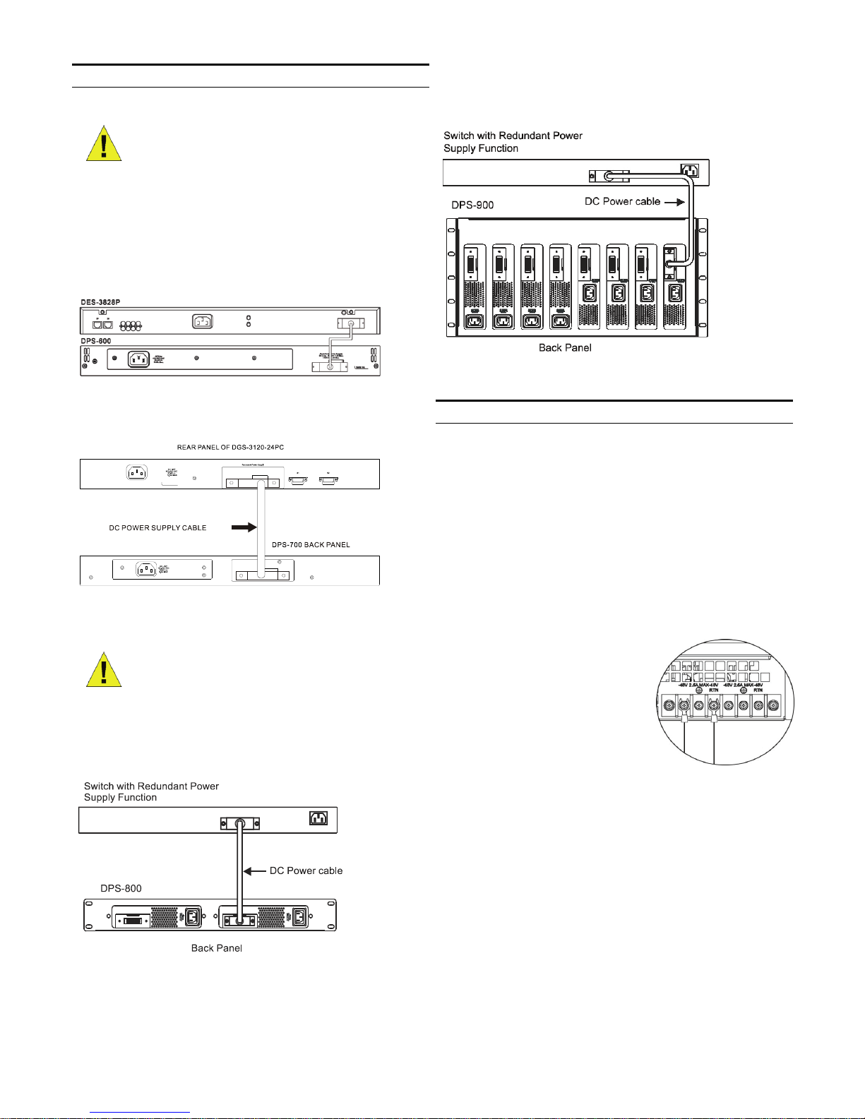
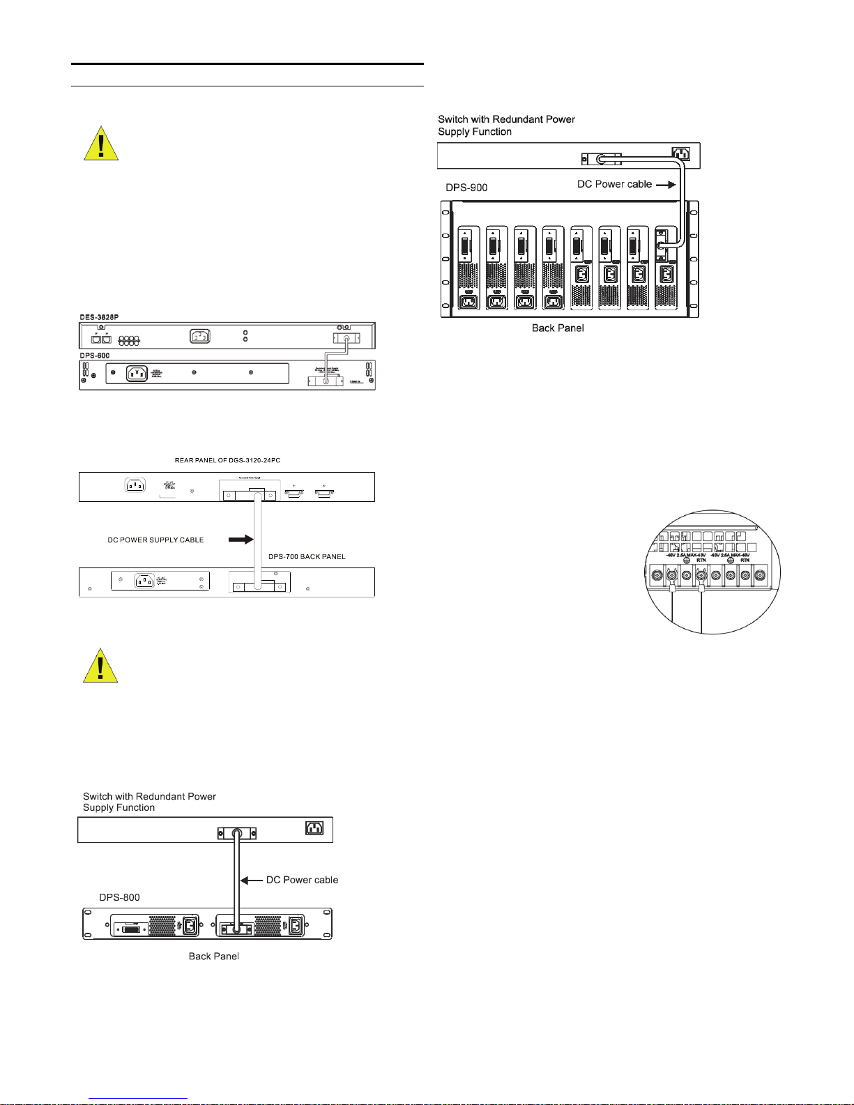
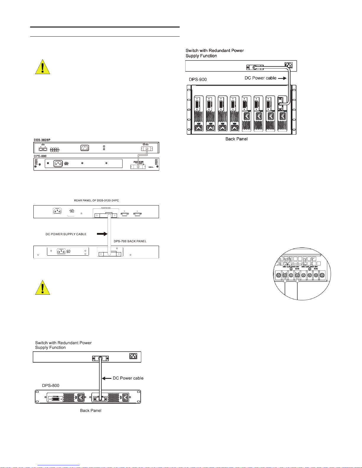
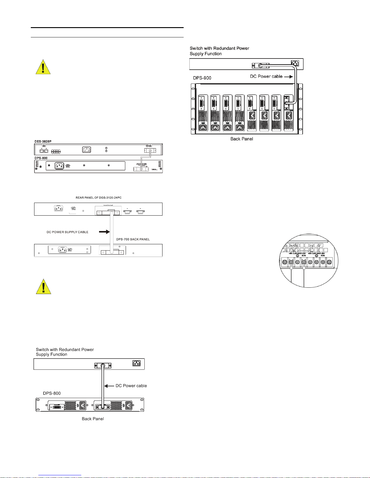
Vous pouvez connecter les périphériques DPS-200, DPS-
300, DPS-500, DPS-500DC et DPS-600 au commutateur
principal à l’aide d’un câble d’alimentation CC à 14 broches.
De même, le DPS-700 utilise un câble d’alimentation CC à
22 broches. Un câble d’alimentation CA triphasé standard
permet de connecter l’alimentation redondante à la source
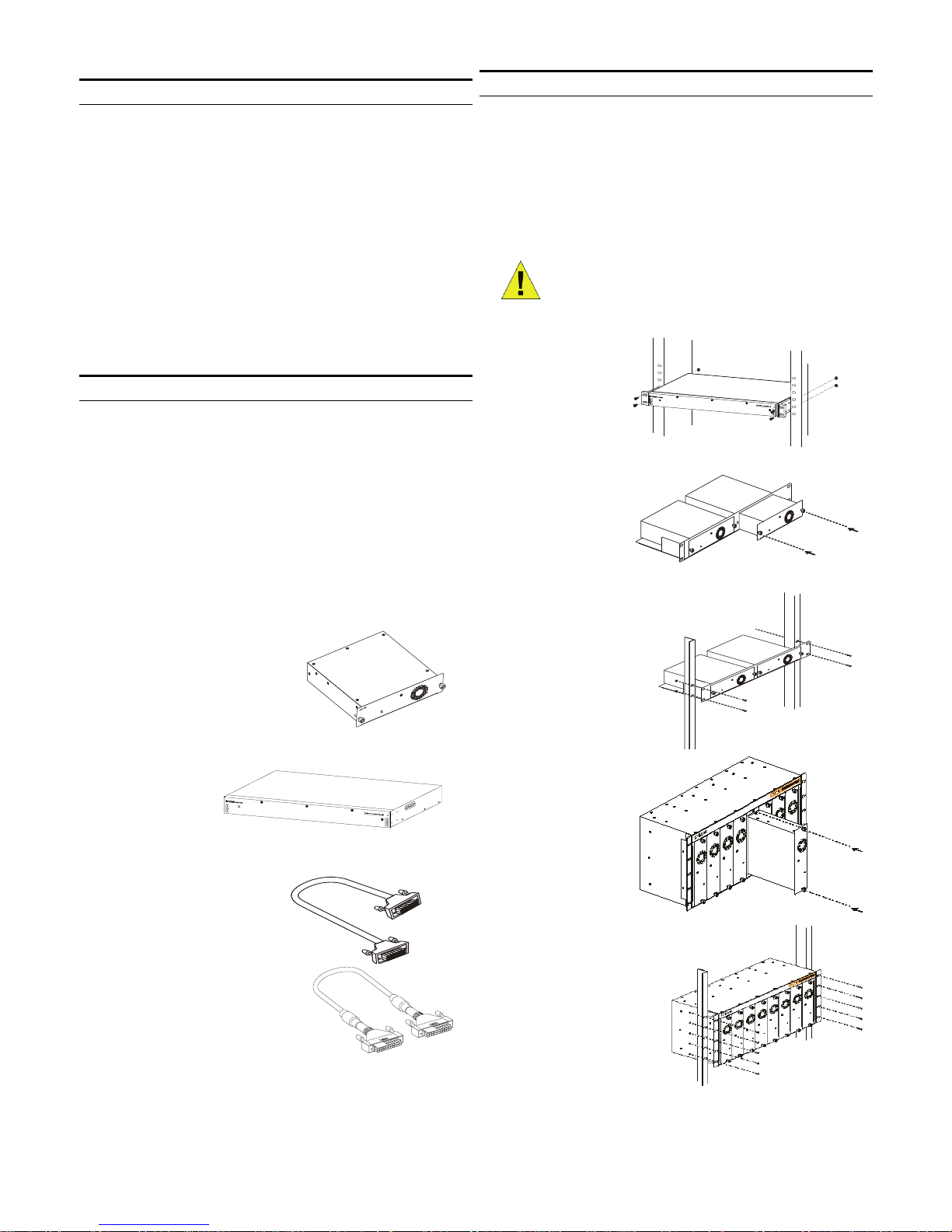
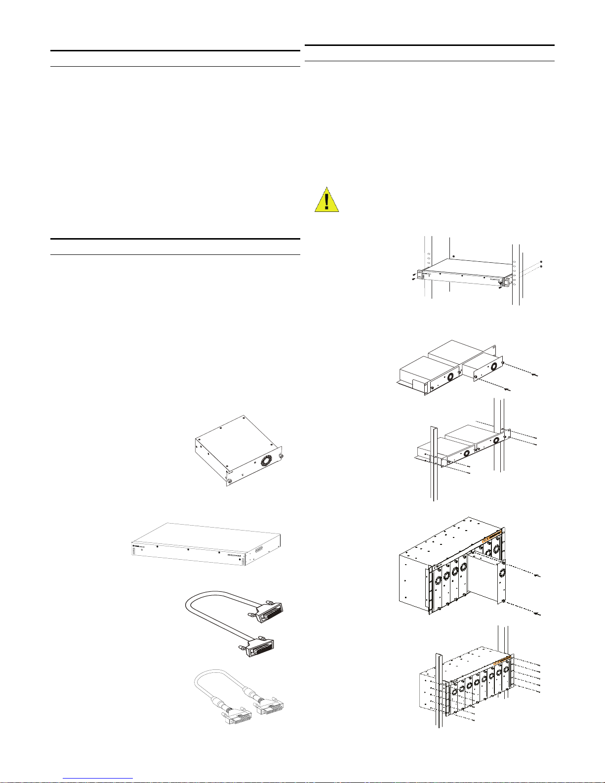
d’alimentation principale. Bloc d'alimentation redondant
RPS simple (DPS-600/700)
.
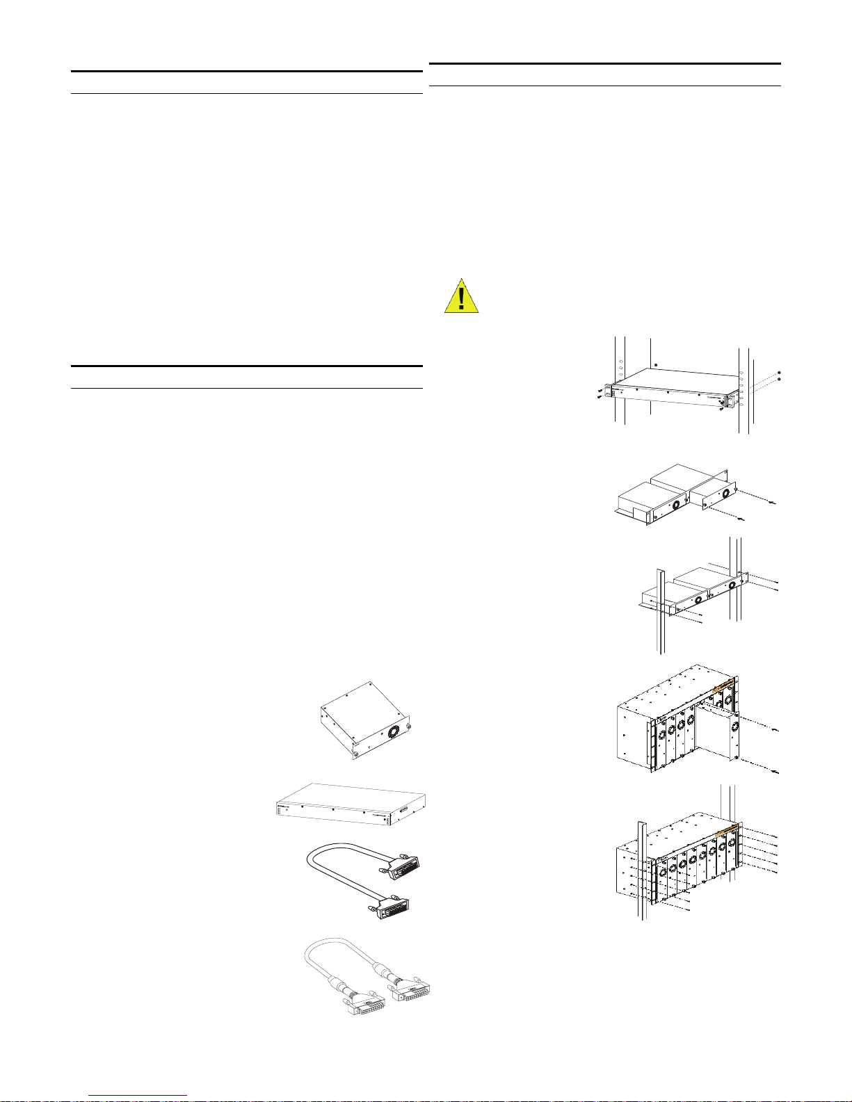
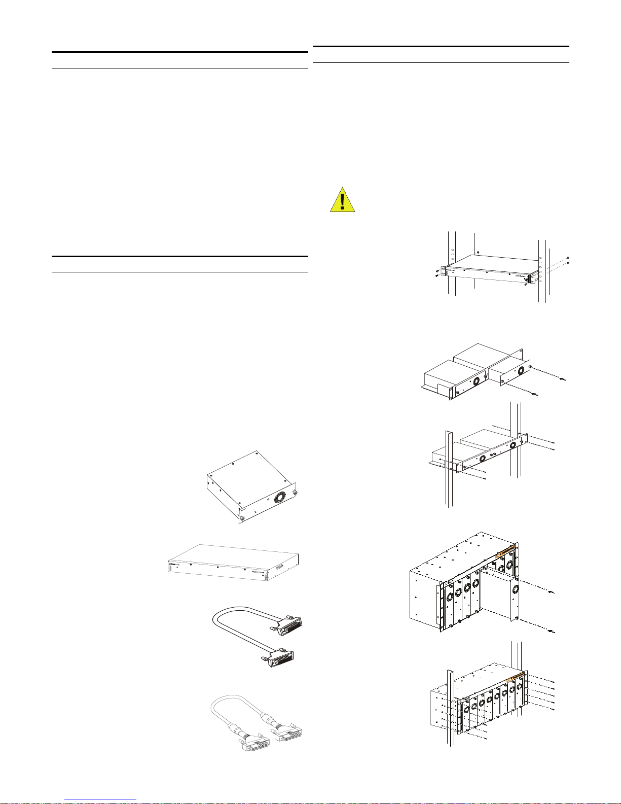
RPS Simple (DPS-200/DPS-300 /DPS-
500/DPS-500DC)
RPS Simple (DPS-600/700)
Câble d’alimentation CC à 14 broches.
Câble d’alimentation CC à 22
broches
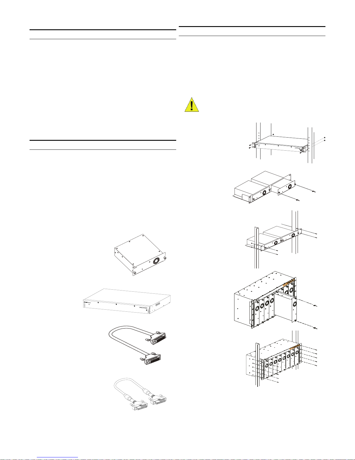
Installation des RPS
Les RPS simples DPS-200, 300, 500, et 500DC peuvent
être installées dans une armoire standard par
l'intermédiaire d’un rack DPS-800 ou DPS-900. Le DPS-
900 est un rack de support de taille- standard (5U) conçu
pour supporter 8 alimentations RPS.
Le DPS-800 est également un support de rack de taille
standard (1.25U ) conçu pour supporter 2 alimentations
RPS.
Les unités installées RPS peuvent être des DPS-200s,
DPS-300s, DPS-500s, DPS-500DCs, ou une combinaison
de ces derniers.
NOTE: le DPS-500DC ne peut s’insérer
que dans un châssis DPS-800
Installation d’un DPS-
600/700 dans un rack
électronique standard
Insertion d’un RPS dans
un Rack DPS-800.
Installation d‘un DPS-800 dans un
rack standard.
Insertion d’un RPS dans
un rack DPS-900.
Installation d‘un DPS-900
dans un rack standard

Connexion à un commutateur
Attention: assurez-vous que l’alimentation
redondante soit déconnectée de
l’alimentation principale avant de la connecter
au commutateur. Ceci pourrait endommager
l’alimentation interne du commutateur.
Insérer l’une des extrémités du câble d’alimentation DC de
14 pins fournis dans l’emplacement prévu sur le
commutateur et l'autre extrémité dans l'alimentation du
RPS.
Connexion d'un DPS-600 à un commutateur
Connexion d'un DPS-700 à un commutateur
Attention : Ne connectez pas le DPS-700 à
un commutateur à l’aide d’un câble
d’alimentation CC à 14 broches. L’utilisation
de ce câble, au lieu du câble d’alimentation
CC à 22 broches correct, risque
d’endommager l’équipement.
Connexion d’un RPS inséré dans un rack DPS-800 à un
commutateur.
Connexion d’un RPS inséré dans un rack DPS-900 à un
commutateur.
En utilisant un câble standard de courant alternatif, relier
l'alimentation du RPS à la source principale de courant
alternatif.
Une LED verte sur l'avant du DPS-200/DPS-300/DPS-
500/DPS-600 s’allumera pour indiquer un raccordement
réussi.
Connexion électrique continue DC (DPS-500DC)
1. Connecter fermement la source d'alimentation DC aux
contacts négatifs et de positif du câblage.
La polarité négative (-) se
connecte au contacteur -48V.
La polarité positive (+) se
connecte au contacteur -48V
RTN
Si disponible, la terre peut-
être reliée au contacteur
central.
2. Serrer les vis de contact pour fixer le raccordement.
Aucun changement de configuration de commutateur n'est
nécessaire en se reliant au RPS.

Introducción
Una fuente de alimentación redundante proporciona una
solución económica y sencilla a los irritantes fallos en las
fuentes de alimentación internas, que pueden provocar la
caída de un dispositivo individual o de la red completa.
En una fuente de alimentación redundante, un circuito de
detección integrado supervisa continuamente la fuente de
alimentación interna del switch. En caso de que se
produzca una caída del suministro eléctrico, la fuente de
alimentación redundante se activa inmediatamente para
que no se interrumpa el servicio del switch y los
dispositivos conectados.
Con esto, se consigue una infraestructura de red más fiable
y se protege la red de un fallo aislado en la fuente de
alimentación de un dispositivo de red.
Descripción
Las fuentes de alimentación redundantes DPS-200, DPS-
300, DPS-500, DPS-500DC y DPS-600 están diseñadas
para suministrar energía a los switches compatibles. La
DPS-200 entrega una potencia de 60 vatios, la DPS-300
entrega 90 vatios, las DPS-500/500DC entregan 140 vatios
y la DPS-600 entrega 500 vatios.
Los módulos DPS-200, DPS-300, DPS-500, DPS-500DC y
DPS-600 se pueden conectar al conmutador mediante un
cable de alimentación de corriente continua de 14 patillas.
De forma similar, el módulo DPS-700 utiliza un cable de
alimentación de corriente continua de 22 patillas. Por el
otro lado, un cable de alimentación de tres clavijas
estándar conecta el sistema de energía redundante a la
toma de corriente alterna principal.
RPS individual (DPS-200/DPS-300/
DPS-500/DPS-500DC)
RPS individual (DPS-
600/700)
Cable de alimentación CC de 14
patillas
Cable de alimentación CC de 22
patillas
Instalación
Las fuentes de alimentación redundantes DPS-200, 300,
500 y 500DC pueden instalarse en un rack normalizado
mediante los chasis DPS-800 y DPS-900. DPS-900 es un
chasis normalizado de 5U de altura y puede albergar hasta
8 fuentes de alimentación redundantes. DPS-800 es
también un chasis normalizado de 1,25U de altura y puede
albergar hasta 2 fuentes de alimentación redundantes. Las
fuentes de alimentación redundantes instaladas pueden ser
DPS-200, DPS-300, DPS-500, DPS-500DC, o una
combinación de las mismas.
Instalación de un DPS-
600/700 en un rack para
dispositivos
electrónicos estándar
Insertar una fuente
de alimentación
redundante en un
chasis DPS-800
Instalar una DPS-800
en un rack
normalizado
Insertar una
fuente de
alimentación
redundante en un
chasis DPS-900
Instalar una DPS-900
en un rack
normalizado
NOTA: la DPS-500DC únicamente puede
insertarse en un chasis DPS-800

Conexión del conmutador
Precaución: Hay que desconectar la fuente
de alimentación redundante de la red eléctrica
antes de conectarla al switch. Pueden
provocarse daños en la fuente de
alimentación interna del switch si se conecta
directamente una fuente de alimentación
redundante activa.
Conecte un extremo del cable de alimentación de continua
de 14 patillas al switch y el otro extremo a la fuente de
alimentación redundante.
Conexión de un DPS-600 a un conmutador
Conexión de un DPS-700 a un conmutador
Precaución: No conecte el DPS-700 al
conmutador utilizando un cable de
alimentación CC de 14 patillas. El equipo se
podría dañar si se utiliza este cable en lugar
del cable de alimentación CC de 22 patillas
correcto.
Conectar una fuente de alimentación redundante de un
chasis DPS-800 a un switch
Conectar una fuente de alimentación redundante de un
chasis DPS-900 a un switch
Emplee un cable estándar trifásico de corriente alterna para
conectar la fuente de alimentación redundante al suministro
eléctrico general. Si se ilumina el LED verde del frontal de
DPS-200/DPS-300/DPS-500/DPS-600 indicará una
conexión correcta.
Conectar la fuente de alimentación de continua
(DPS-500DC)
1. Fije la alimentación de continua a los contactos negativo
y positivo de la clema.
El polo negativo (-) se
conecta al contacto -48V.
El polo positivo (+) se
conecta al contacto -48V
RTN.
Si existe toma de tierra,
deberá conectarse al
contacto central.
2. Asegure los tornillos de los contactos para conseguir una
buena conexión.
No es necesario modificar la configuración del switch
cuando se conecta a la fuente de alimentación redundante.

Introduction
A redundant power supply provides a low-cost, simple
solution to the equally simple yet vexing problem of internal
power supply failure, which can result in the shutdown of a
single switching device or an entire network.
With a redundant power supply connected, an integrated
detection circuit continuously monitors the switch’s internal
power supply. In the event of a power interruption, the
redundant power supply is immediately triggered so that the
switch and connected devices can continue providing
service.
This results in a more reliable network infrastructure and
protects the network from a single failure of a network
device power supply.
Description
The DPS-200, DPS-300, DPS-500, DPS-500DC and DPS-
600 are redundant power supply units designed to conform
to the wattage requirements of the switches being
supported. DPS-200 operates at 60 watts, DPS-300
operates at 90 watts, DPS-500/500DC at 140 watts, and
DPS-600 at 500watts.
The DPS-200, DPS-300, DPS-500, DPS-500DC, and DPS-
600 can connect to the master switch using a 14-pin DC
power cable. Similarly, the DPS-700 uses a 22-pin DC
power cable. A standard, three-pronged AC power cable
connects the redundant power supply to the main power
source.
Single RPS (DPS-200/DPS-300
/DPS-500/DPS-500DC)
Single RPS (DPS-
600/700)
14-pin DC power cable
22-pin DC power cable
Installation of the RPS
The single RPS DPS-200, 300, 500, and 500DC can be
installed to the standard rack via the RPS rack DPS-800
and DPS-900. DPS-900 is a standard-size rack mount (5U
in height) designed to hold up to 8 redundant power
supplies. The DPS-800 is also a standard-size rack mount
(1.25U in height) designed to hold up to 2 redundant power
supplies. Installed RPS units can be DPS-200s, DPS-300s,
DPS-500s, DPS-500DCs, or a combination of the above.
NOTE: The DPS-500DC can only be inserted
into a DPS-800
Installing a DPS-600/700 in
a standard electronics
rack
Inserting a single
RPS into a DPS-
800 RPS rack
Installing a DPS-800 in a
standard electronics
rack
Inserting a single
RPS into a DPS-
900 RPS rack
Installing a DPS-900 in
a standard electronics
rack

Switch Connection
Caution: The redundant power supply should
be disconnected from its power source before
connecting to the switch. Directly connecting
a powered RPS to the switch may cause
damage to the switch’s internal power supply.
Insert one end of the 14-pin DC power cable into the
receptacle on the switch and the other end into the
redundant power supply.
Connecting a DPS-600 to a switch
Connecting a DPS-700 to a switch
Caution: Do not connect the DPS-700 to the
switch using the 14-pin DC power cable. The
equipment may be damaged if using this
cable instead of the correct 22-pin DC power
cable.
Connecting a single RPS in a DPS-800 rack to a switch
Connecting a single RPS in a DPS-900 rack to a switch
Using a standard AC power cable, connect the redundant
power supply to the main AC power source. A green LED
on the front of the DPS-200/DPS-300/DPS-500/DPS-600
will glow to indicate a successful connection.
Connecting DC Power (DPS-500DC)
1. Firmly attach the DC power source to the negative and
positive contacts on the wiring assembly.
The negative pole (-)
connects to the -48V contact.
The positive pole (+)
connects to the -48V RTN
contact.
If available, an earth ground
may be connected to the
center contact post.
2. Tighten the contact screws to secure the connection.
No change in switch configuration is necessary when
connecting to the RPS.

Введение
Резервный источник питания обеспечивает
экономичное ипростое решение проблемы
обеспечения бесперебойной работы коммутаторов или
сети вцелом, при возникновении неполадок свнешним
источником питания.
При использовании резервного источника питания,
встроенная схема обнаружения непрерывно
контролирует внутренний источник питания
коммутатора. Вслучае прекращения подачи
электропитания, резервный источник питания
мгновенно включится, так что коммутатор и
подключенные кнему устройства, продолжают
функционировать.
Это приведет кболее надежной сетевой
инфраструктуре изащитит сеть от выхода из строя
единственного блока питания сетевого устройства.
Описание
Резервные источники питания DPS-200, DPS-300, DPS-
500, DPS-500DC иDPS-600 разработаны для
удовлетворения требованиям потребляемой мощности
коммутаторов. DPS-200 обеспечивает потребляемую
мощность 60 Вт, DPS-300 обеспечивает потребляемую
мощность 90 Вт, DPS-500/500DC – 140 Вт иDPS-600 –
500 Вт.
Подключение резервных источников питания DPS-200,
DPS-300, DPS-500, DPS-500DC иDPS-600 к
коммутатору осуществляется спомощью 14-контактного
кабеля. Аналогичным образом DPS-700 использует 22-
контактный кабель. Для подключения резервного
источника питания ксети используется стандартный 3-
контактный кабель.
Один RPS (DPS-200/DPS-300
/DPS-500/DPS-500DC)
Один RPS
(DPS-600/700)
14-контактный кабель
питания постоянного тока
22-контактный кабель питания
постоянного тока
Установка RPS
Резервные источники питания DPS-200, 300, 500, и
500DC можно устанавливать встандартную стойку с
помощью шасси DPS-800 иDPS-900. DPS-900 – шасси
для RPS стандартного размера (5 стандартных
устройств ввысоту), разработано для установки до 8-ми
резервных источников питания. DPS-800 – шасси для
RPS стандартного размера (1.25 стандартных устройств
ввысоту) разработано для установки 2-хрезервных
источников питания. Это могут быть DPS-200, DPS-300,
DPS-500, DPS-500DC или их комбинация.
ЗАМЕЧАНИЕ:DPS-500DC может
устанавливаться только вDPS-800
Установка DPS-600/700
встандартную стойку
Поместите
источник
резервного
питания вшасси
DPS-800
Монтаж DPS-800 в
стандартную стойку
для оборудования
Поместите
источник
резервного
питания вшасси
DPS-900
Монтаж DPS-900 в
стандартную стойку
для оборудования

Подключение ккоммутатору
Внимание:Перед подключением к
коммутатору отключите из розетки
резервный источник питания, иначе
подключение RPS ккоммутатору может
повлечь выход из строя внутреннего
источника питания коммутатора.
Подключите один конец 14-контактного кабеля питания
постоянного тока кразъему на коммутаторе идругой
конец крезервному источнику питания.
Подключение резервного источника питания DPS-
600 ккоммутатору
Подключение резервного источника питания DPS-
700 ккоммутатору
Предупреждение:Не подключайте DPS-
700 ккоммутатору спомощью 14-
контактного кабеля питания постоянного
тока. Использование данного кабеля
вместо 22-контактного кабеля питания
постоянного тока может привести к
повреждению оборудования.
Подключение RPS, вмонтированного вшасси DPS-
800 ккоммутатору сфункцией RPS
Подключение RPS, вмонтированного вшасси DPS-
900 ккоммутатору сфункцией RPS
Спомощью стандартного кабеля питания переменного
тока подключите резервный источник питания к
основному источнику питания переменного тока.
Зеленый индикатор на передней панели DPS-200/DPS-
300/DPS-500/DPS-600 загорится, показывая
правильность подключения.
Подключение источника питания постоянного тока
(DPS-500DC)
1. Надежно подключите разъемы питания постоянного
тока непосредственно котрицательному и
положительному контактам на монтажной схеме.
Отрицательный полюс (-)
подключите кконнектору -
48V.
Положительный полюс (+)
подключите кконнектору -
48V RTN.
При наличии,
заземляющий провод
можно закрепить к
центральной мачте.
2. Закрепите разъемы винтами для надежного
соединения.
Не изменяйте настройки коммутатора во время
подключения крезервному источнику питания.

介紹
當交換器內建電源供應器故障,導致單一交換器或整個網路
癱瘓時,備用電源供應器具備低成本、簡易快速的特性,可
有效解決交換器內建電源供應器故障所造成的問題。
在備用電源供應器與交換器連結時,整合式電路偵測裝置便
會持續監控內建電源供應器運作狀態;發生電源中斷事件
時,備用電源供應器便立即被觸發啟動,讓交換器及介接設
備可持續提供服務。
此舉將可提供更高信任度的網路基礎架構,並保護單一設備
因電源供應器故障導致整個網路癱瘓的窘境。
產品描述
D-Link 設計 DPS-200, DPS-300, DPS-500, DPS-500DC 及
DPS-600 等多款備用電源供應器,可依交換器電源功率需求
選擇符合的備用電源供應器。DPS-200 輸出功率為 60 瓦,
DPS-300 輸出功率為 90 瓦,DPS-500/500DC 輸出功率為
140 瓦,DPS-600 則為 500 瓦。
D-Link DPS-200, DPS-300, DPS-500, DPS-500DC 與DPS-
600 使用 14-Pin 的DC 電源線來連接交換器,跟 DPS-700
使用的 22-Pin DC 電源線相當類似。一般標準,三孔 AC 電
源線連接至備援電源供應器的主要電源插座上。
獨立備援電源供應器
DPS-200/DPS-300 /DPS-500/DPS-
500DC
獨立備援電源供應器
(DPS-600/700)
14-pin DC 電源線
22-pin DC 電源線
安裝備用電源供應器
RPS DPS-200、300、500, 及500DC 獨立式備用電源供應
器可置入 DPS-800 及DPS-900 標準機架式備用電源專用機
箱,安裝於標準機櫃中。DPS-800(1.25U 高度)可置入兩
個備用電源供應器,DPS-900(5U 高度)則可置入八個備
用電源供應器。可置入 DPS-800 及DPS-900 的獨立式備用
電源供應器計有 DPS-200、DPS-300、DPS-500,亦可混和
置入上述三款備用電源供應器 。
注意事項:DPS-500DC 若欲置入備用電源供
應器專用機箱,僅可置於 DPS-800;DPS-900
不支援 DPS-500DC。
安裝 DPS-600/700 到標準
電子機櫃裏
將獨立式備用電源供
應器置入 DPS-800
備用電源供應器專用
機箱
將DPS-800 安裝於標準
機櫃中。
將獨立式備用電源
供應器置入 DPS-
900 備用電源供應
器專用機箱
將DPS-900 安裝於標準
機櫃中

交換器的連接
注意:備用電源供應器未連接至交換器前,請勿
將備用電源供應器電源線插入電源插座。交換器
若直接連結已過電之備用電源供應器可能導致交
換器內建電源供應器損壞。
將14-pin DC 電源連接線一端連接至交換器備用電源插孔,
另一端則連結至備用電源供應器。
連接 DPS-600 到一台交換器。
連接 DPS-700 到一台交換器。
注意:不用使用 14-Pin DC 電源線來連接 DPS-
700 與交換器。假如使用 14-Pin DC 電源線來取
代正確的 22-Pin DC 電源線,可能導致設備的
損壞。
將置於 DPS-800 機箱內的獨立式備用電源供應器連結至交
換器。
將置於 DPS-900 機箱內的獨立式備用電源供應器連結至交
換器。
以標準 AC 電源連接線連接至 AC 電源插座,在 DPS-
200/DPS-300/DPS-500/DPS-500DC/DPS-600 前面板 LED
狀態顯示燈號為綠色,即表示連結成功。
連結 DC 電源(DPS-500DC)
1. 確實將 DC 電源線連接至備用電源供應器集線裝置正負
極。
負極(-)連接至-48V 接頭。
正極(+)連接至-48V RTN 接
頭。
建議將接地線連結在集線裝
置中間接頭。.
2. 鎖緊連結螺絲,確保連接無誤。
連結備用電源供應器,交換器無須更動任何設定。

说明
冗余电源提供了一个简单、低成本的可能会导致交换设备或
整个网络的关闭的内部电源故障问题。
连接了冗余电源后,一个完整的检测电路将会持续的监控交
换机的内部电源。在发生断电事故时,冗余电源将会被立即
触发,这样交换机和连接好的设备就可以继续提供服务。
这就形成了一个更加稳定的网络结构,并且可保护网络不受
网络设备电源故障的影响。
描述
DPS-200、DPS-300、DPS-500、DPS-500DC 和DPS-600
是被设计用来满足交换机支持功率的冗余电源设备。DPS-
200 在60 瓦特下工作,DPS-300 在90 瓦特下工作,DPS-
500/500DC 在140 瓦特下工作,DPS-600 在500 瓦特下工
作。
DPS-200、DPS-300、DPS-500、DPS-500DC 和DPS-600
可以通过 14 针直流电源线连接到交换机,与之类似 DPS-
700 使用 22 针直流电源线。以上冗余电源均采用标准的三角
插头交流电源线受电。
单个 RPS (DPS-200/DPS-300 /DPS-
500/DPS-500DC)
单个 RPS(DPS-600/700)
14 针直流电源线
22 针直流电源线
安装 RPS
注意:DPS-500DC 只能用于 DPS-800
将DPS-600/700 安装到标准
的电器设备机架
将一个单一的 RPS
插入到 DPS-800
RPS 机架中
在标准的电子机架上安装
DPS-800
将一个单一的 RPS
插入到 DPS-900
RPS 机架中
在标准的电子机架上安
装DPS-900
连接交换机
警告:在连接到交换机之前冗余电源应该从它
的电源上断开。直接将通电的 RPS 连接到交
换机可能会造成交换机内部电源损坏。
将14 针DC 电源线的一端插入交换机的插座,另一端插入冗
余电源设备。

将DPS-600 链接到交换机
将DPS-700 链接到交换机
警告:不可使用 14 针直流电源线连接 DPS-
700 和交换机,否则将损坏设备。
将DPS-800 机架上的 RPS 连接到交换机
将DPS-900 机架上的 RPS 连接到交换机
使用标准的 AC 电源线缆,将冗余电源按揭到主 AC 电源。
连接成功后,DPS-200/DPS-300/DPS-500/DPS-600 前面的
绿色指示灯会开始闪烁。
连接 DC 电源(DPS-500DC)
1. 将DC 电源牢固的连接到配线板
上的正负极。
负极(-)接在-48V 接点上。
正极(+)接在-48V Re 接点
上。
一根接地线可能会连接在中
间的接点上。
2. 将接触螺钉扭紧以保证连接的安全。
当连接到 RPS 时不需要更改交换机的设置。


Fourth Edition (February 2011)
6RPSQML...05G
RECYCLABLE
This manual suits for next models
4
Table of contents
Languages:
Other D-Link Power Supply manuals

D-Link
D-Link DPS-520 User manual

D-Link
D-Link DIS-PWR40AC/RU User manual

D-Link
D-Link mydlink DSP-W215 User manual

D-Link
D-Link mydlink DSP-W215 User manual

D-Link
D-Link DCS-80-5 User manual

D-Link
D-Link DPS-520 User manual

D-Link
D-Link DMC-1001 - Power Supply - hot-plug User manual

D-Link
D-Link DGS-6604-SK User manual

D-Link
D-Link DIS-PWR180AC/RU User manual

D-Link
D-Link DPS-200A User manual