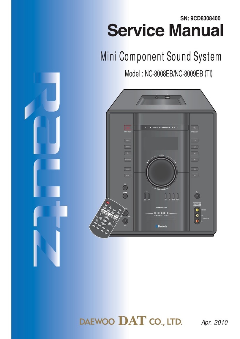
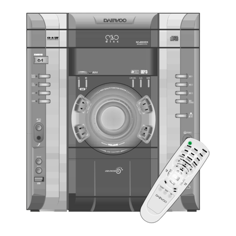
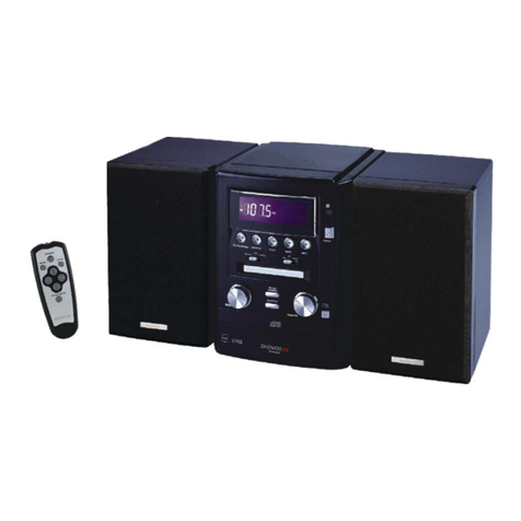
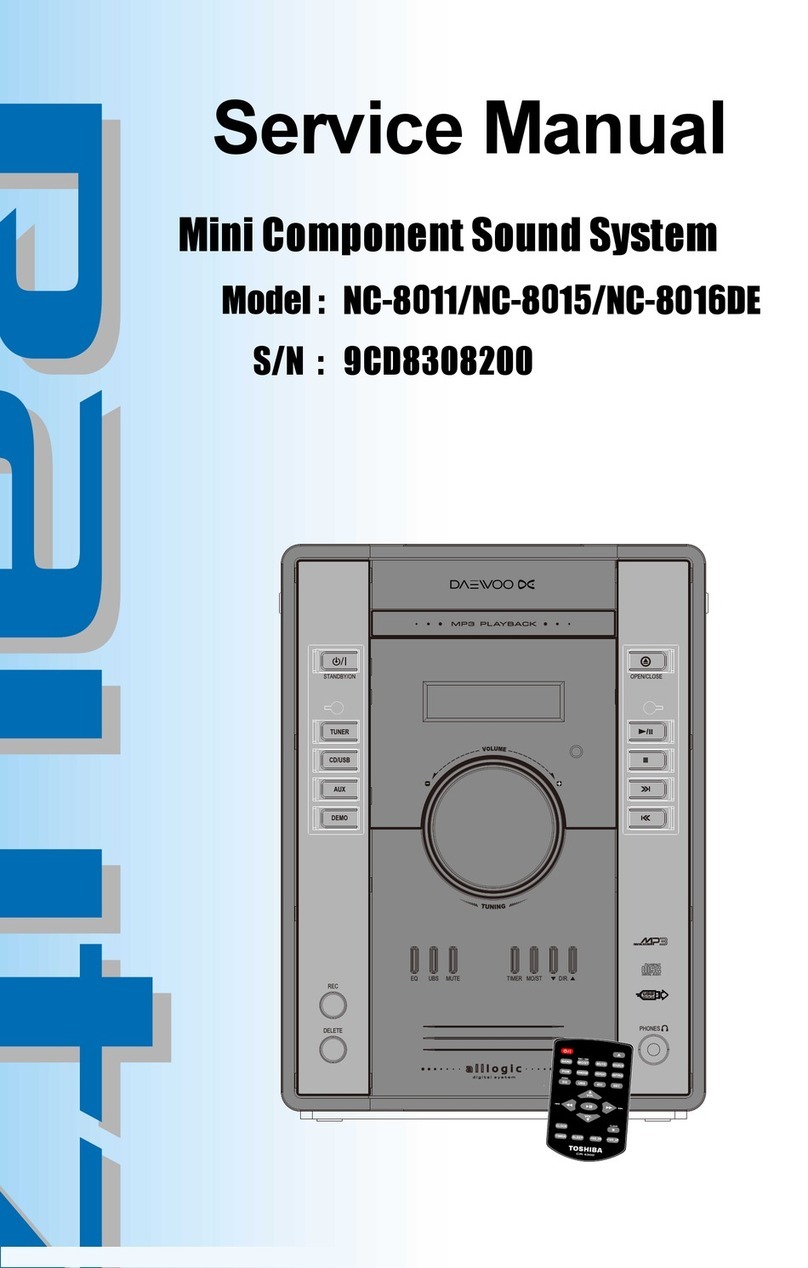
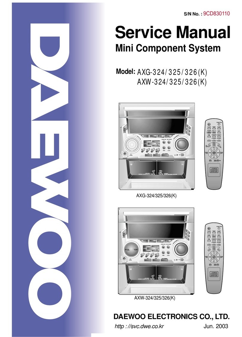
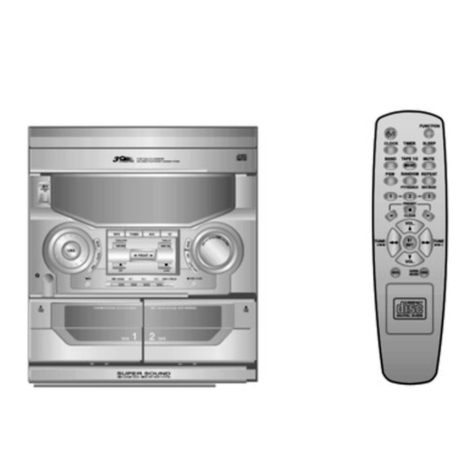
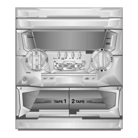
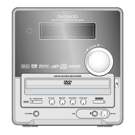
Daewoo MC-5210SU User manual

6
7
10
Aug.2012
USB/MP3/CD/Micro Systems
MC-5210SU
Service Manual
All manuals and user guides at all-guides.com
all-guides.com

Table of Contents
SAFETY PRECAUTIONS 1
2
3
4
5
6
7
8
9
MC-5210SU
SPECIFICATIONS
P.C.B PATTERN LAYOUT
WIRING DIAGRAM
BLOCK DIAGRAM
EXPLODED VIEW AND MECHANICAL PARTS LIST
PART LIST
SCHEMATIC DIAGRAM
ADJUSTMENT
APPENDIX-ELECTRICA L PART LIST 10
USB/MP3/CD/Micro Systems
All manuals and user guides at all-guides.com

Safety Precautions
1
2
3
4
5
6
7
1
9
10
11
12
13
14
15
1
2
3
4
5
6
7
1
9
10
11
12
13
14
15
WARNING
: TO PREVENT FIRE OR ELECTRIC SHOCK, DO NOT EXPOSE
THIS APPLIANCE TO RAIN OR MOISTURE.
CAUTION :
TO REDUCE THE RISK OF ELECTRIC SHOCK, DO NOT
REMOVE COVER (OR BACK). NO USER SERVICEABLE PARTS
INSIDE.
REFER SERVICING TO QUALIFIED SERVICE PERSONNEL.
THIS SYMBOL IS INTENDED TO ALERT THE USER TO THE
PRESENCE OF UNINSULTED "DANGEROUS VOLTAGE"
WITHIN THE PRODUCT'S ENCLOSURE THAT MAY BE
SUFFICIENT MAGNITUDE TO CONSTITUTE A RISK OF
ELECTRIC SHOCK TO PERSONS.
THIS SYMBOL IS INTENDED TO ALERT THE USER TO THE
PRESENCE OF IMPORTANT OPERATING AND MAINTENANCE
(SERVICING) INSTRUCTIONS IN THE LITERATURE
ACCOMPANYING THE APPLIANCE.
CAUTION
TO PREVENT ELECTRIC SHOCK, DO NOT USE THIS POLARIZED AC
PLUG WITH AN EXTENSION CORD, RECEPTACLE OR OTHER OUTLET
UNLESS THE BLADES CAN BE FULLY INSERTED TO PREVENT BLADE
EXPOSURE.
LASER SAFETY
THIS UNIT EMPLOYS A LASER. ONLY QUALIFIED SERVICE PERSONNEL
SHOULD REMOVE THE COVER OR ATTEMPT TO SERVICE THIS DEVICE
DUE TO POSSIBLE EYE INJURY.
CAUTION :
USE OF ANY CONTROLS, ADJUSTMENTS, OR PROCEDURES
OTHER THAN THOSE SPECIFIED HEREIN MAY RESULT IN HAZARDOUS
RADIATION EXPOSURE.
CAUTION :
TO PREVENT ELECTRIC SHOCK, MATCH WIDE BLADE OF
PLUG TO WIDE SLOT, FULLY INSERT.
ATTENTION :
POUR EVITER LES CHOCS ELECTRIQUES, INTRODUIRE
LA LAME LA PLUS LARGE DE LA FICHE DANS LA BORNE CORRESPON-
DANTE DE LA PRISE ET POUSSER JUSQU'AU FOND.
Important Safety Instructions
- All the safety and operating instructions should be read before
the appliance is operated.
- The safety and operating instructions should be retained for
future reference.
- All warnings on the appliance and in the operating instructions
should be adhered to.
- All operating and use instructions should be followed.
1. Water and Moisture - The appliance should not be used near
water - for example, near a bathtub, washbowl, kitchen sink,
laundry tub, in a wet basement, orneara swimming pool,
and the like.
2. Carts and Stands - The appliance
should be used only with a cart or
stand that is recommended by th
manufacturer.
3. An appliance and cart combination
should be moved with care. Quick
stops, excessive force, and uneven
surfaces may cause the appliance
and cart combination to overturn.
4. Wall or Ceiling Mounting - The appli-
ance should be mounted to a wall or
ceiling only as recommended by the manufacturer.
5. Ventilation - The appliance should be situated so that its
location or position does not interfere with its proper
ventilation. For example, the appliance should not be situated
on a bed, sofa, rug, or similar surface that may block the
ventilation openings; or, placed in a built-in installation, such
as a bookcase or cabinet that may impede the flow of air
through the ventilation openings.
6. Heat - The appliance should be situated away from heat
sources such as radiators, heat registers, stoves, or other
appliances (including amplifiers) that produce heat.
7. Power Sources - The appliance should be connected to a
power supply only of the type described in the operating
instructions or as marked on the appliance.
8. Grounding or Polarization - The precautions that should be
taken so that the grounding or polarization means of an
appliance is not defeated.
9. Power - Cord Protection - Power-supply cords should be
routed so that they are not likely to be walked on or pinched
by items placed upon or against them, paying particular
attention to cords at plugs, convenience receptacles, and the
point where they exit from the appliance.
10.Protective Attachment Plug - If the appliance is equipped with
an attachment plug having overload protection. This is a
safety feature. See Instruction Manual for replacement or
resetting of protective device. If replacement of the plug is
required, be sure the service technician has used a
replacement plug specified by the manufacturer that has the
same overload protection as the original plug.
11.Cleaning - The appliance should be cleaned only as
recommended by the manufacturer.
12.Power Lines - An outdoor antenna should be located away
from power lines.
CAUTION
RISK OF ELECTRIC SHOCKS
DO NOT OPEN
PORTABLE CART
Figure 2
All manuals and user guides at all-guides.com

Specifications
1
11
1
2
9
Power supply
AC :127V / 60Hz
Operating :12 Watt
41.2×24.8×66.59mm / 9.7kg
Operating Voltage (Option)
Power consumption
Dimensions (W x D x H) / Weight
FM Section
(FM ANT Impedance : 75 ohms)
General Specifications
No. Test Items Unit Nominal Limit Remark1 Remark2
1 Intermediate frequency MHz 10.7 +/-0.1
2 Tuning range MHz
87.5-108.00
+/-0.35
3 Dial calibration 90.1MHz KHz +/-700
106.1MHz KHz +/-700
90.1KHZ uV
4 Max sensitivity IHF 98.1MHz uV
106.1MHz uV
30 dB quieting 90.1MHz dB 18 26
5 98.1MHz dB 18 26
sensitivity 106.1MHz dB 18 26
6 IF rejection 90.1MHz dB 50 45
7 S/N ratio1mV input 22.5 KHz dev dB 40 35
8 3 dB limiting sensitivity dB 10 20
9 T.H.D 22.5 KHz dev % 1 3
10 AM suppression dB 32 25
11 Modulation hum100mv 22.5KHz dev dB 40 35
12 AFC hold rang - 3 dB l mV KHz 300~600
13 Frequency response -6dB Hz 40 100
with usec pre-emphasis KHz 5 3
14 Overload break mV
15 Output power 32 KHz dev 1mV W
16 10% THD power 75KHz dev. 1mV W 2.5 ±0.2
17 Hum & Noise level VR MIN mV1
18 Spurious response dB
19 Muting on level uV
20 Muting bandwidth KHz
21 Alternate channel selectivity 0.1 mV
input +/- KHz dB
22 Capture ration 1mV dB
23 FAIL OUTPUT VOLTAGE (DC) V
(AC)%
90.1MH dB 20 26
24 AUTO STOP SENS 98.1MH dB 20 26
106.1M dB 20 26
2 2
2
2
All manuals and user guides at all-guides.com

NO. Test items Unit Norminal Limit Remark Remark2
25 MPX indicator sens. dB 22 28
100Hz dB
W/Z 19KHz
26 MPX separati 1k Hz dB 30 25
FILTER
10K Hz dB
27 MPX T.H.D. Main 400 Hz %2 5 W/Z 19KHz
L. or R. 1K Hz % 2 5 FILTER
MAX 50dB quieting
28 Sensitivity 98MHz dB
2 MPX S/N ratio dB 35 25 W/Z 19KHz
FILTER
30 FM signal meter %
31 SCA Signanl Suppression dB
No. Unit Norminal Limit Remark1 Remark2
FM 1000uV 22.5K DEV.
dB 0 0
(FM LEVEL 0dB) CD-10 dB RECORDING LEVEL
dB 0 +/-3
4
Audio LEVEL BALANCE
Specifications
2 2
9
All manuals and user guides at all-guides.com

NO. Test items Unit Nominal Limit Remark 1 Remark2
1 LEVEL 0dB TRACK 1.4,10 dB 2 +/-4
FREQUENCY RESPONSE 100Hz - 12KHz dB
2 LEVEL 0dB TRACK 30,34 dB 35 30
JIS A
NET IN
CHANNEL SEPARATION 1KHz
3 LEVEL 0d TRACK 14 % 0.5 1
JIS A
NET IN
TOTAL HARMONNIC DISTORTION
4 LEVEL 0dB TRACK 1, 23 dB 55 45
JIS A
NET IN
S/N RATIO
5 LEVEL 0dB Verm
OUT PUT LEVEL
6 LEVEL 0dB TRACK 1 dB 0 +/-3
UNBALANCE L/R
7 10% THD POWER SONY 3 TRACK 1 W 2.5 +/-0.3
8 CD SAME VOL dB
PLAYABILITY
NO TEST ITEMS TEST
DISC
1 DEFECT DISC INTERRUPTION PHILIPS PLAYABLE WITHOUT ANY
5A AUDIBLE ERROR
INFORMATION LAYER 600um
2 PHILIPS PLAYABLE WITHOUT ANY
BLACK DOT AT READ OUT SIDE 5A AUDIBLE ERROR
500um
3 PHILIPS
SIMULATED FINGERPRINT 5A PLAYABLE WITHOUT ANY
TRACK AUDIBLE ERROR
18/19
ACCESS TIME PHILIPS
START - UP 1ST TRACK </= 5SEC
SHORT ACCESS TIME TR 1< - >2 </= 3 SEC
LONG ACCESS TIME TR 1 < - > UNIT </= 10 SEC
TEST DISC TYPE 3 (SONY YEDS - )
2 X OVERSAMPLING, 16 BIT D/A CONVERTER
CD Section
Specifications
22
All manuals and user guides at all-guides.com
all-guides.com

Schematic Diagram
●
POWER AMP Section
33
All manuals and user guides at all-guides.com

margaiDcitamehcS
1
. MPEG Section
33
.
All manuals and user guides at all-guides.com

●
FRONT Section
Schematic Diagram
3
3
3
All manuals and user guides at all-guides.com

<TOP VIEW>
P.C.B Pattern Layout
●SMPS/AMP
4
44
All manuals and user guides at all-guides.com

●
< BOTTOM VIEW >
SMPS/AMP
44
P.C.B Pattern Layout
All manuals and user guides at all-guides.com
all-guides.com

●MPEG
< TOP V
4
44
IEW >
All manuals and user guides at all-guides.com

●MPEG
44
<BOTTOM VIEW>
All manuals and user guides at all-guides.com

P.C.B Pattern Layout
●
< TOP VIEW >
44
FRONT
All manuals and user guides at all-guides.com

P
.C.B Pattern Layout
●FRONT
< BOTTOM VIEW >
3
4
3
4
All manuals and user guides at all-guides.com

Wiring Diagram
11
5
5
All manuals and user guides at all-guides.com
all-guides.com

Block Diagram
66
All manuals and user guides at all-guides.com

11
6
7
8
7
Adjustment
All manuals and user guides at all-guides.com

Exploded View and Mechanical Parts List
1
88
All manuals and user guides at all-guides.com

MC-5210SU BOM LIST
ASS‘Y
E
V
E
SE
Q
LOC PART CODE PART NAME PART DESC Q’TY
MAIN PCB
ASSY 1 11000 USB8008PRS MAIN PCB ASSY USB8008PR MB ASS’Y 1
MAIN PCB
ASSY 2 2 U2. 158-800821-01 IC IC. BK1080 (SSOP16) 1
MAIN PCB
ASSY 1P7228ATC.ICIL8-080100-331.1CI22
MAIN PCB
ASSY 14132TPCICI41-722802-331.5CI32
MAIN PCB
ASSY 2 4 Q1. 133-02314S-00 IC IC 78L05 (TR Tube Style) 1
MAIN PCB
ASSY 2 5 Q6. 133-507805-15 IC VOLTAGE REGULATOR HT7533-
1(TO-92) 1
MAIN PCB
ASSY 2 6 Q2.5. 131-457533-13 TRANSISTOR TRANSISTOR 772 2
MAIN PCB
ASSY 1P288BSPROTSISNART48-277022-1314Q72
MAIN PCB
ASSY 2 8 Q3. 131-240882-67 TRANSISTOR TRANSISTOR S8550 1
MAIN PCB
ASSY 2 9 Q15. 131-448550-71 TRANSISTOR TRANSISTOR 2SD8050D SMT 1
MAIN PCB
ASSY 2 10 Q9.11.12.13.14. 131-448050-1A TRANSISTOR TRANSISTOR JE 9014 SMT 5
MAIN PCB
ASSY 42004NIEDOIDEDOIDA1-410944-131.8.7.6.5D112
MAIN PCB
ASSY 2 12 D9.10.11. 130-314002-89 DIODE DIODE LL4148 (LL-34) 3
MAIN PCB
ASSY 2 13 ZD1.DZ1. 130-344148-7D DIODE ZENER DIODE ZMM8V2 (LL-34) 2
MAIN PCB
ASSY 2 14 FS2. 130-340082-7D FUSE FUSE T1.6AL 250V (5X20MM) 1
MAIN PCB
ASSY 2 15 FOR F2 . 182-221600-00 FUSE HOLDER FUSE HOLDER (5*20 MM) 2
MAIN PCB
ASSY 2 16 FM ANT.ACx2. 733-005020-00 BRASS EYELET BRASS EYELET DIA 2*4 3
MAIN PCB
ASSY 2 17 CN7. 718-020040-00 SOCKET PIN SOCKET 2PIN 2.5MM 1
MAIN PCB
ASSY 2 18 CN2.5. 160-102255-01 SOCKET PIN SOCKET 3PIN 2.5MM 2
MAIN PCB
ASSY 2 19 CN6.
2012-06-14 160-103255-01 SOCKET PIN SOCKET 12PIN 2.0MM 1
MAIN PCB
ASSY 2 20 J1.2.4-7.9-12.14-
16.18.19.21.22.24-27. 160-112205-01 JUMPER WIRE JUMPER WIRE 40*0.5MM 22
MAIN PCB
ASSY 2 21 R1. C16-005000-00 RESISTOR CAR. RESISTOR 33 OHM 1/2W 1
MAIN PCB
ASSY 2 22 R45. 113-330205-12 RESISTOR CAR. RESISTOR 0 OHM (0805) 1
MAIN PCB
ASSY 2 23 L1. 113-000005-85 RESISTOR CAR RESISTOR 0 OHM (0603) 1
MAIN PCB
ASSY 2 24 R53. 113-000005-63 RESISTOR CAR RESISTOR 10 OHM (0603) 1
MAIN PCB
ASSY 2 25 R55. 113-100005-63 RESISTOR CAR. RESISTOR 100 OHM (0805) 1
MAIN PCB
ASSY 2 26 R35.36.43.48.52. 113-101005-85 RESISTOR CAR. RESISTOR 330 OHM (0603) 5
MAIN PCB
ASSY 2 27 R56. 113-331005-63 RESISTOR CAR. RESISTOR 470 OHM (0603) 1
9
9
9
Part List
All manuals and user guides at all-guides.com
Table of contents
Other Daewoo Stereo System manuals

Daewoo
Daewoo AMI-917L User manual

Daewoo
Daewoo XG-332V User manual

Daewoo
Daewoo AXG-327 User manual

Daewoo
Daewoo DV - 115 User manual

Daewoo
Daewoo AMI-225M User manual

Daewoo
Daewoo AMI-208MC User manual

Daewoo
Daewoo MC?15UBW User manual

Daewoo
Daewoo AXG-322 User manual

Daewoo
Daewoo AMI-310 User manual

Daewoo
Daewoo AMI-326LW/RW User manual

Daewoo
Daewoo NC-8011 User manual

Daewoo
Daewoo MC-5911SC User manual

Daewoo
Daewoo RG-361 User manual

Daewoo
Daewoo AMI-V225M User manual

Daewoo
Daewoo AMI-910L User manual

Daewoo
Daewoo XG-522 User manual

Daewoo
Daewoo XD-615 User manual

Daewoo
Daewoo AMI-329LW/RW User manual

Daewoo
Daewoo AMI-230 User manual

Daewoo
Daewoo EKE User manual