• Indoor Units • R-410A • FCQ-C8VEB
• Split Sky Air • Indoor Units
8
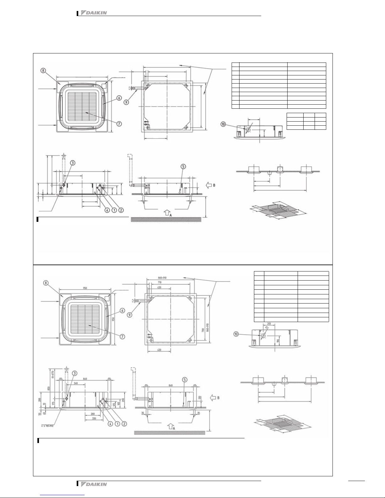
5 Dimensional drawing & centre of gravity
5 - 2 Dimensional drawing for auto cleaning panel
)&4&9(%
7:
127(6
/RFDWLRQRIWKHQDPHSODWHV
8QLWERG\RQWKHFRQWUROER[
'HFRUDWLRQSDQHORQWKHSDQHOIUDPHDWWKHPRWRUVLGHXQGHUWKH
FRUQHUFRYHU
:KHQLQVWDOOLQJDQRSWLRQDODFFHVVRU\UHIHUWRWKHLQVWDOODWLRQGUDZLQJV
)RUWKHIUHVKDLULQWDNHNLWDQLQVSHFWLRQSDUWLVQHFHVVDU\
0DNHVXUHWKHVSDFLQJEHWZHHQWKHFHLOLQJDQGWKHFDVVHWWHLVQRPRUH
WKDQPP0D[FHLOLQJRSHQLQJPP
:KHQWKHFRQGLWLRQVH[FHHG&DQG5+LQGHFHLOLQJRUIUHVK
DLULVLQFOXGHGLQWRWKHFHLOLQJDQDGGLWLRQDOLQVXODWLRQLVUHTXLUHG
SRO\HWK\OHQHIRDPWKLFNQHVVPPRUPRUH
1U 1DPH 'HVFULSWLRQ
/LTXLGSLSHFRQQHFWLRQ $ÀDUHFRQQHFWLRQ
*DVSLSHFRQQHFWLRQ %ÀDUHFRQQHFWLRQ
'UDLQSLSHFRQQHFWLRQ 932','
3RZHUVXSSO\HQWU\KROH
7UDQVPLVVLRQZLULQJHQWU\KROH
$LUGLVFKDUJHRSHQLQJ
$LUVXFWLRQJULOOH
&RUQHUGHFRUDWLRQFRYHU
'UDLQKRVH 2','
.QRFNRXWKROH
3LSLQJVLGH
'UDLQVLGH
9,(:$
+DQJLQJEROW
$GMXVWDEOHa
6XVSHQVLRQSRVLWLRQ
RUOHVV
a&HLOLQJRSHQLQJ
6XVSHQVLRQSRVLWLRQ
a&HLOLQJRSHQLQJ
6HHQRWH
6HHQRWH 6HHQRWH
RUPRUH
,QVWDOODWLRQVSDFH
9,(:%
3OHDVHUHVSHFWWKHGLVWDQFHVDVVKRZQRQ¿JXUHEHORZ
,QVWDOODWLRQGLUHFWLRQ
3LSLQJ 3LSLQJ
'XVW
RSHQLQJ
6XFWLRQ
JULOO
([WHUQDO
VXUIDFH
OLJKW
9HQWLODWRU 2WKHUXQLW
RUPRUH
RUPRUH
RUPRUH
'RHVQRWFRXQWIRUEXLOGLQOLJKW
6SDFHQHHGHGWRHQWHUZLWKYDFXXPFOHDQHUWXEH
.HHSWKHH[KDXVWRIGHFRUDWLRQSDQHOIUHH
PPRU
PRUH
PPRU
PRUH
PPRU
PRUH
PPRU
PRUH PPRU
PRUH
PPRU
PRUH
,QFDVHDGLVFKDUJHRSHQLQJLVFORVHGZLWKWKHµVHDOLQJPHPEHU¶RSWLRQ
WKHGLVWDQFHRIPPFDQEHUHGXFHGWRPPRQWKHFORVHGVLGH
0RGHO $ %
)&4
)&4
)&4);)4
FCQ100-140C8VEB
3TW32524-1
NOTES
Location of the nameplates:
Unit body: on the control box.
Decoration panel: on the panel frame at the motor side under the
corner cover
When installing an optional accessory, refer to the installation drawings.
For the fresh air intake kit an inspection part is necessary
Make sure the spacing between the ceiling and the cassette is no more
than 35mm. Max. ceiling opening: 910mm
When the conditions exceed 30°C and RH 80% in de ceiling or fresh
air is included into the ceiling, an additional insulation is required
(polyethylene foam, thickness 10mm or more).
1.
•
•
2.
•
3.
4.
Nr Name Description
1 Liquid pipe connection Ø9.52 flare connection
2 Gas pipe connection Ø15.90 flare connection
3 Drain pipe connection VP25 (O.D.Ø32, I.D. Ø25)
4 Power supply entry hole
5 Transmission wiring entry hole
6 Air discharge opening
7 Air suction grille
8 Corner decoration cover
9 Drain hose O.D.Ø32, I.D. Ø26
10 Knock out hole
Piping side
Drain side
VIEW A
Hanging bolt
Adjustable (0~675)
710 (Suspension position)
300 or less
860~910 (Ceiling opening)
780 (Suspension position)
860~910 (Ceiling opening)
See note 3
See note 3 See note 3
1500 or more
(Installation space)
VIEW B
Please respect the distances as shown on figure below6.
Installation direction5.
Piping Piping
Dust
opening
Suction
grill
External
surface
light (*1)
Ventilator Other unit
256
1500 or more
2000 or more
4000 or more
(*1) Does not count for build in light
(*2) Space needed to enter with vacuum-cleaner tube.
(*3) Keep the exhaust of decoration panel free.
1500mm or
more (*4)
200mm or
more (*4)
1500mm or
more (*4)
200mm or
more (*4) 1500mm or
more (*4)
1500mm or
more (*4)
(*4) In case a discharge opening is closed with the ‘sealing member’ option,
the distance of 1500mm can be reduced to 500 mm on the closed side.


 null")