manuals.online logo
Brands
  1. Home
  2. •
  3. Brands
  4. •
  5. Daikin
  6. •
  7. Air Conditioner
  8. •
  9. Daikin VRV W T Series User manual

Daikin VRV W T Series User manual

This manual suits for next models

14

Other Daikin Air Conditioner manuals

Daikin UATYA-BBY1 User manual

Daikin

Daikin UATYA-BBY1 User manual

Daikin FCTY223CV1 User manual

Daikin

Daikin FCTY223CV1 User manual

Daikin FXFQ-P Instruction Manual

Daikin

Daikin FXFQ-P Instruction Manual

Daikin FXFQ12MVJU User manual

Daikin

Daikin FXFQ12MVJU User manual

Daikin FTXP35L5V1B User manual

Daikin

Daikin FTXP35L5V1B User manual

Daikin FXZQ-M8V1B Instruction manual

Daikin

Daikin FXZQ-M8V1B Instruction manual

Daikin FTXB20C2V1B User manual

Daikin

Daikin FTXB20C2V1B User manual

Daikin VRV Aurora Series User manual

Daikin

Daikin VRV Aurora Series User manual

Daikin D-Series User manual

Daikin

Daikin D-Series User manual

Daikin FVXM25A2V1B User manual

Daikin

Daikin FVXM25A2V1B User manual

Daikin Super Multi NX FTXG25JV1BW User manual

Daikin

Daikin Super Multi NX FTXG25JV1BW User manual

Daikin FDA200AXVEB User manual

Daikin

Daikin FDA200AXVEB User manual

Daikin FDXS25F2VEB User manual

Daikin

Daikin FDXS25F2VEB User manual

Daikin RXTP25N2V1B8 User manual

Daikin

Daikin RXTP25N2V1B8 User manual

Daikin FXAQ15PAV1 User manual

Daikin

Daikin FXAQ15PAV1 User manual

Daikin BSVQ36PVJU User manual

Daikin

Daikin BSVQ36PVJU User manual

Daikin Perfera FTXM50R User manual

Daikin

Daikin Perfera FTXM50R User manual

Daikin ARXF20E5V1B User manual

Daikin

Daikin ARXF20E5V1B User manual

Daikin FTKS50BVMA8 User manual

Daikin

Daikin FTKS50BVMA8 User manual

Daikin ARXG35E3V1B User manual

Daikin

Daikin ARXG35E3V1B User manual

Daikin RXM18VVJU User manual

Daikin

Daikin RXM18VVJU User manual

Daikin Altherma EBLQ011CAV3 User manual

Daikin

Daikin Altherma EBLQ011CAV3 User manual

Daikin FFQ09W2VJU9 User manual

Daikin

Daikin FFQ09W2VJU9 User manual

Daikin Quaternity FTXG09HVJU User manual

Daikin

Daikin Quaternity FTXG09HVJU User manual

Popular Air Conditioner manuals by other brands

Fujitsu ASYG 09 LLCA installation manual

Fujitsu

Fujitsu ASYG 09 LLCA installation manual

York HVHC 07-12DS Installation & owner's manual

York

York HVHC 07-12DS Installation & owner's manual

Carrier Fan Coil 42B Installation, operation and maintenance manual

Carrier

Carrier Fan Coil 42B Installation, operation and maintenance manual

intensity IDUFCI60KC-3 installation manual

intensity

intensity IDUFCI60KC-3 installation manual

Frigidaire FAC064K7A2 Factory parts catalog

Frigidaire

Frigidaire FAC064K7A2 Factory parts catalog

Sanyo KS2432 instruction manual

Sanyo

Sanyo KS2432 instruction manual

LG MultiV Series installation manual

LG

LG MultiV Series installation manual

CLIMAVENETA a-CHD U-2T 606+2209 OPERATING AND INSTALLATION Manual

CLIMAVENETA

CLIMAVENETA a-CHD U-2T 606+2209 OPERATING AND INSTALLATION Manual

Midea EWK06CW5 user manual

Midea

Midea EWK06CW5 user manual

Pioneer FAB Series installation manual

Pioneer

Pioneer FAB Series installation manual

SPT WA-1511S user manual

SPT

SPT WA-1511S user manual

Mitsubishi Electric Mr.Slim MSZ-A24NA operating instructions

Mitsubishi Electric

Mitsubishi Electric Mr.Slim MSZ-A24NA operating instructions

Mitsubishi Electric PUHZ-RP50VHA4 Service manual

Mitsubishi Electric

Mitsubishi Electric PUHZ-RP50VHA4 Service manual

Panasonic CS-S18HKQ Service manual

Panasonic

Panasonic CS-S18HKQ Service manual

Panasonic CS-E15NKE3 operating instructions

Panasonic

Panasonic CS-E15NKE3 operating instructions

Gree GWH18TC-K3DNA1B/I Service manual

Gree

Gree GWH18TC-K3DNA1B/I Service manual

Friedrich ZoneAire Compact P08SA owner's manual

Friedrich

Friedrich ZoneAire Compact P08SA owner's manual

Taurus Alpatec R750 manual

Taurus Alpatec

Taurus Alpatec R750 manual

manuals.online logo
manuals.online logoBrands
  • About & Mission
  • Contact us
  • Privacy Policy
  • Terms and Conditions

Copyright 2025 Manuals.Online. All Rights Reserved.

Installation manual
VRV W T-Series water-cooled system air conditioner English
Manuel d'installation
Climatiseur système refroidi par eau VRV W série T Français
Manual de instalación
Sistema de climatización condensado por agua VRV W serie T Español
Installation manual
VRV W T-Series water-cooled system air conditioner
RWEQ96TAYCU
RWEQ120TAYCU
RWEQ144TAYCU
RWEQ192TAYCU
RWEQ216TAYCU
RWEQ240TAYCU
RWEQ264TAYCU
RWEQ288TAYCU
RWEQ312TAYCU
RWEQ336TAYCU
RWEQ360TAYCU
RWEQ384TAYCU
RWEQ408TAYCU
RWEQ432TAYCU
Read these instructions carefully before installation.
Keep this manual in a handy place for future reference.
This manual should be left with the equipment owner.
4 Preparation
Installation manual
9
RWEQ96~432TAYCU
VRV W T-Series water-cooled system air conditioner
4P540122-1B – 2018.11
3.5.5 Possible options for the outside unit
INFORMATION
Refer to the technical engineering data for the latest option
names.
Refrigerant branching kit
In case of heat pump system
Description Model name
Refnet header KHRP26M22H9
KHRP26M33H9
KHRP26M72H9
KHRP26M73HU9
Refnet joint KHRP26A22T9
KHRP26A33T9
KHRP26M72TU9
KHRP26M73TU9
In case of heat recovery system
Description Model name
Refnet header KHRP25M33H9
KHRP25M72H9
KHRP25M73HU9
Refnet joint KHRP25A22T9
KHRP25A33T9
KHRP25M72TU9
KHRP25M73TU9
For the selection of the optimal branching kit, please refer to
"4.3.3 To select refrigerant branch kits" on page 12.
Outside multi connection piping kit
In case of heat pump system
Number of outside units Model name
2 BHFP22T84U
3 BHFP22T126U
In case of heat recovery system
Number of outside units Model name
2 BHFP26T84U
3 BHFP26T126U
Cool/heat selector
In order to control the cooling or heating operation from a central
location, the following option can be connected:
Description Model name
Cool/heat change over switch KRC19-26A6
Cool/heat change over PCB BRP2A81
With optional fixing box for the
switch
KJB111A
External control adaptor (DTA104A61/62)
To instruct specific operation with an external input coming from a
central control the external control adaptor can be used. Instructions
(group or individual) can be instructed for low noise operation and
power consumption limitation operation.
PC configurator cable (999482P3)
You can make several commissioning field settings through a
personal computer interface. For this option 999482P3 is required
which is a dedicated cable to communicate with the outside unit.
4 Preparation
4.1 Overview: Preparation
This chapter describes what you have to do and know before going
on-site.
It contains information about:
▪ Preparingtheinstallationsite
▪ Preparingtherefrigerantpiping
▪ Preparingthewaterpiping
▪ Preparingtheelectricalwiring
4.2 Preparing installation site
4.2.1 Installation site requirements of the
outside unit
CAUTION
This unit is designed for indoor installation only.
▪ Provide required service space around the unit as stated in the
technical engineering book or in section "11.2 Service space:
Outside unit" on page 48 of this manual.
▪ Ensurethatthefoundationisstrongenoughtosupporttheweight
of the unit and the floor is flat to prevent vibration and noise
generation.
▪ Make sure the area is well ventilated. Do NOT block any
ventilation openings.
▪ Makesuretheunitislevel.
▪ Make sure to install the unit in a machine room that is free of
moisture. The unit is designed for indoor use only.
▪ Select the location of the unit in such a way that the sound
generated by the unit does not disturb anyone, and the location is
selected according the applicable legislation.
Do NOT install the unit in the following places:
▪ Inpotentiallyexplosiveatmospheres.
▪ In places where there is machinery that emits electromagnetic
waves. Electromagnetic waves may disturb the control system,
and cause malfunction of the equipment.
▪ In places where there is a risk of fire due to the leakage of
flammable gases (example: thinner or gasoline), carbon fiber,
ignitable dust.
▪ Inplaceswherecorrosivegas(example:sulphurousacidgas)is
produced. Corrosion of copper pipes or soldered parts may cause
the refrigerant to leak.
▪ Inplaceswhereamineraloilmist,sprayorvapormaybepresent
in the atmosphere. Plastic parts may deteriorate and fall off or
cause water leakage.
NOTE
This is a class A product. In a domestic environment this
product may cause radio interference in which case the
user may be required to take adequate measures.
8 Commissioning
Installation manual
41
RWEQ96~432TAYCU
VRV W T-Series water-cooled system air conditioner
4P540122-1B – 2018.11
Error code (Auto
backup possible) Error contents
H9
Outside unit inside air thermistor (R1T) abnormality
HC Water inlet thermistor (R9T) abnormality
Water outlet thermistor (R10T) abnormality
J3 Discharge pipe thermistor (R12T) abnormality
Compressor body thermistor (R13T) abnormality
J4 Plate heat exchanger gas thermistor (R4T)
abnormality
J5 Suction pipe thermistor (R3T) abnormality
J6 Plate heat exchanger liquid thermistor (R7T)
abnormality
J7 Receiver outlet liquid pipe thermistor (R6T)
abnormality
Subcooling heat exchanger outlet liquid pipe
thermistor (R8T) abnormality
Injection pipe thermistor (R11T) abnormality
J9 Subcooling heat exchanger outlet gas pipe
thermistor (R5T) abnormality
Exhaust heat cancellation heat exchanger gas
pipe thermistor (R2T) abnormality
JA High pressure sensor abnormality
JC Lowpressuresensorabnormality
L1 Inverter PCB abnormality
L3 Reactor temperature rise abnormality
L4
Inverter radiation fin temperature rise abnormality
L5 Inverter compressor instantaneous overcurrent
L8 Inverter compressor overcurrent
L9 Inverter compressor startup abnormality
LC Transmission error between inverter PCB and
outside unit main PCB
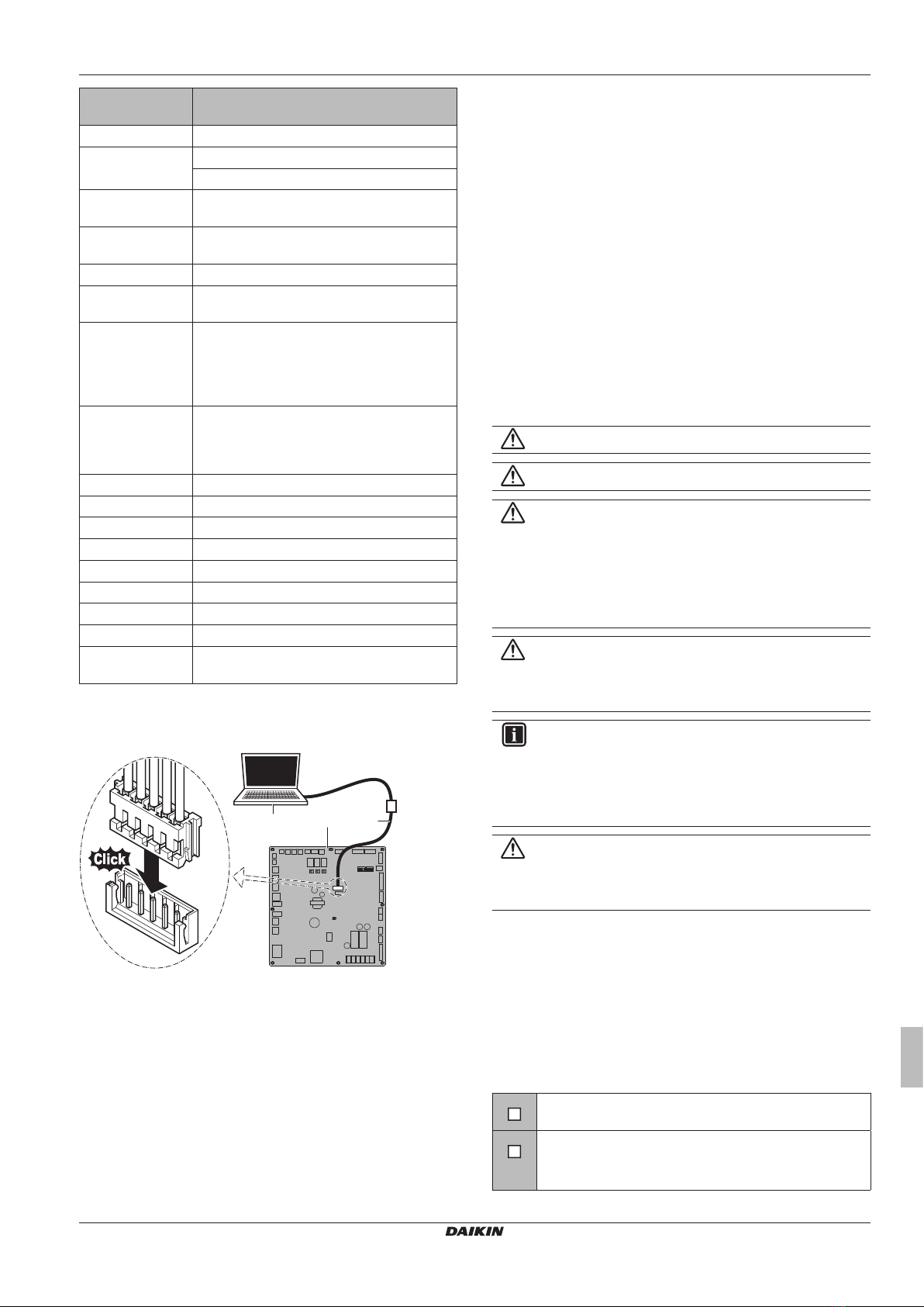
7.2.9 To connect the PC configurator to the
outside unit
X27A
ab
c
2
345
HJ S T
X27A
A1P
aPC
bCable (999482P3)
cOutside unit main PCB
8 Commissioning
8.1 Overview: Commissioning
After installation and once the field settings are defined, the installer
is obliged to verify correct operation. Therefore a test run must be
performed according to the procedures described below.
This chapter describes what you have to do and know to
commission the system after it is configured.
Commissioning typically consists of the following stages:
1 Checking the "Checklist before commissioning".
2 Performing a test run.
3 If necessary, correcting errors after abnormal completion of the
test run.
4 Operating the system.
8.2 Precautions when commissioning
DANGER: RISK OF ELECTROCUTION
DANGER: RISK OF BURNING
CAUTION
Do not perform the test operation while working on the
indoor units.
When performing the test operation, not only the outside
unit, but the connected indoor unit will operate as well.
Working on an indoor unit while performing a test operation
is dangerous.
CAUTION
Do not insert fingers, rods or other objects into the air inlet
or outlet. Do not remove the fan guard. When the fan is
rotating at high speed, it will cause injury.
INFORMATION
During the first running period of the unit, the required
power may be higher than stated on the nameplate of the
unit. This phenomenon is caused by the compressor, that
needs a continuous run time of 50 hours before reaching
smooth operation and stable power consumption.
NOTE
Be sure to turn on the power 6 hours before operation in
order to have power running to the crankcase heater and
to protect the compressor.
During test operation, the outside unit and the indoor units will start
up. Make sure that the preparations of all indoor units are finished
(field piping, electrical wiring, air purge, ...). See installation manual
of the indoor units for details.
8.3 Checklist before commissioning
After the installation of the unit, first check the following items. Once
all below checks are fulfilled, the unit must be closed, only then can
the unit be powered up.
You read the complete installation and operation
instructions, as described in the installation manual.
Installation
Check that the unit is properly installed, to avoid abnormal
noises and vibrations when starting up the unit.