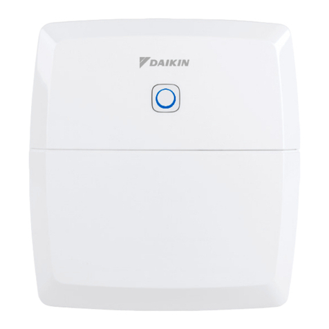
Daikin homecontrols EKRUFHT61V3 User manual

Installation and operation manual
Daikin Home Controls
Floor Heating Controller – 6 zones
EKRUFHT61V3

A
G
B
E
C
F
I
D
H
1

13,6 cm
L
J
K
2
3

4
5

6
7

6
Package contents
Quantity Description
1 Daikin Home Controls Floor Heating Controller –
6 zones
2 Screws 4.0 x 40 mm
2 Plugs 6 mm
1 Installation and operation manual
Documentation © 2022 Daikin Europe N.V., Belgium
All rights reserved. This manual may not be reproduced in any format, either in whole or
in part, nor may it be duplicated or edited by electronic, mechanical or chemical means,
without the written consent of the publisher.
Typographical and printing errors cannot be excluded. However, the information contained
in this manual is reviewed on a regular basis and any necessary corrections will be imple-
mented in the next edition. We accept no liability for technical or typographical errors or the
consequences thereof.
All trademarks and industrial property rights are acknowledged.
Changes may be made without prior notice as a result of technical advances.
4P687170-1
2022.04

7
Table of contents
1 Information about this manual .......................................................... 8
2 Hazard information ........................................................................... 8
3 Daikin Home Controls .....................................................................11
4 Function and accessory overview .................................................. 12
5 Mounting......................................................................................... 13
5.1 Screw mounting .........................................................................13
5.2 DIN rail mounting ....................................................................... 14
6 Start-up........................................................................................... 14
6.1 Installation instructions ..............................................................14
6.2 Installation.................................................................................. 16
6.3 Behaviour after switching on the mains voltage ........................ 17
6.4 Connecting further DHC accessories ........................................ 18
6.4.1 Connecting to the DHC Access Point
via the ONECTA app.........................................................18
7 Manual operation............................................................................ 19
7.1 Switchingon/oheatingzones ..................................................19
8 Troubleshooting.............................................................................. 19
8.1 Duty cycle .................................................................................19
8.2 Errorcodesandashingsequences .........................................20
8.2.1 Flashing sequences of the system LED .......................... 20
8.2.2 Flashing sequences of the channel LED ......................... 21
9 Restore factory settings.................................................................. 22
10 Maintenance and cleaning ............................................................. 23
11 General information about radio operation..................................... 24
12 Technicalspecications.................................................................. 25

8
Information about this manual
1 Information about this manual
Read this manual carefully before beginning operation with your Daikin
Home Controls (DHC) accessories. Keep the manual so you can refer to
it at a later date if you need to. If you hand over the accessory to other
persons for use, hand over this manual as well.
Symbols used:
Attention!
This indicates a hazard.
Please note:
This section contains important additional information.
2 Hazard information
Do not open the accessory. It does not contain any parts that can
be maintained by the user. In the event of an error, have the
accessory checked by an expert.
For safety and licensing reasons (CE), unauthorized change and/or
modicationoftheaccessoryisnotpermitted.
The accessory may only be operated in a dry and dust-free
environmentandmustbe protected fromtheeectsofmoisture,
vibrations, solar or other types of heat radiation, cold and mechanical
loads.

9
Hazard information
The accessory is not a toy; do not allow children to play with it. Do
not leave packaging material lying around. Plastic lms/bags,
pieces of polystyrene, etc. can be dangerous in the hands of a
child.
We do not assume any liability for damage to property or personal
injury caused by improper use or the failure to observe the hazard
information. In such cases, any claim under warranty is extinguished!
For consequential damages, we assume no liability!
Theaccessorymayonlybeusedforxedinstallationsandmustbe
securely attached.
The accessory is part of the building installation. The relevant
national standards and directives must be taken into consideration
during planning and set-up. The accessory has been designed
solely for operation on a 230 V/50 HzAC supply. Only qualied
electricians (to VDE 0100) are permitted to carry out work on the
230 V mains. Applicable accident prevention regulations must be
complied with whilst such work is being carried out. To avoid electric
shocks from the accessory, please disconnect the mains voltage
(trip the miniature circuit-breaker). Noncompliance with the
installationinstructionscancausereorintroduceotherhazards.
When connecting to the terminals, take the permissible cables and
cable cross sections into account.

10
Hazard information
Take the technical data (in particular the maximum permissible
eectiveinstalledloadoftheaccessoryandthetypeofloadtobe
connected) into account before connecting a load! All load data
relatestoohmicloads.Donotexceedthecapacityspeciedforthe
accessory.
The accessory has not been designed to support safety
disconnection.
Exceeding the maximum capacity could lead to the destruction of
theaccessory,resorelectricshocks.
Before the accessory is connected, remove the fuse from the fuse
box or remove the plug from the socket.
Observe the installation instructions for installation in distribution
systems (DIN VDE 0100-410).
The accessory may only be operated within residential buildings.
Using the accessory for any purpose other than that described in
this manual does not fall within the scope of intended use and shall
invalidate any warranty or liability.

11
Daikin Home Controls
3 Daikin Home Controls
This accessory is part of the DHC ecosystem and communicates with a
dedicated wireless connection.
All accessories of the ecosystem can be congured comfortably and
individually via the ONECTA app. The available functions provided by the
DHC ecosystem in combination with other accessories are described in the
DHC Application Guide.
All current technical documents and updates can be found on the product
pages:
https://qr.daikin.eu/?N=EKRUFHT61V3

12
Function and accessory overview
4 Function and accessory overview
TheDHCFloorHeatingControlleroerscomfortableanddemand-based
room-by-room control of your oor heating system, according to your
personal needs, via the ONECTA app in combination with a DHC Access
Point. For further information, see the DHC Application Guide.
TheFloorHeatingControllercanbeusedincombinationwithoorheating,
radiators or Fan Coil Units that are connected to a collector. Up to 6 heating
zones/9 heating circuits can be supported. Furthermore, the accessory
oers operation in heating or cooling mode, provided that your heating
systemoerstheseoperatingmodes.
YoucanexiblymounttheaccessoryusingthesuppliedscrewsoraDIN
rail. With the secure radio communication between the DHC accessories,
thewiringeortiskepttoaminimum.
Accessory overview (see gure 1):
(A) System button and LED
(B) Select button and LED
(C) Slot for opening
(D) Cover
(E) Spring latch for DIN rail mounting
(F) PE connecting terminals
(G) N (neutral conductor) and L (phase conductor) connecting terminals
(H) Heating valves or heat pump connecting terminals
(I) Heating valves connecting terminals

13
Mounting
Cable bushings (see gure 2):
(J) Cable bushing 1
(K) Cable bushing 2
(L) Cable bushing 3
5 Mounting
YoucanexiblymounttheDHCFloorHeatingControllertoawall,usingthe
supplied screws and plugs, or to a DIN rail.
5.1 Screw mounting
To mount the DHC Floor Heating Controller using screws, proceed as
follows:
1. Select a suitable mounting location close to your heating
system.
Make sure that no electricity or similar lines run in the wall at this
location!
2. Use a pen to mark the positions of the two screw holes (with
a distance of 13.6 cm) on the wall (see gure 3).
3. Use an appropriate drill to make the holes.
4. Use the supplied screws and plugs to x the DHC Floor
Heating Controller (see gure 3).

14
Start-up
5.2 DIN rail mounting
To mount the DHC Floor Heating Controller to a DIN rail, proceed as follows:
1. Place the DHC Floor Heating Controller onto the DIN rail
(see gure 4).
2. Press the spring latches (E) upwards (see gure 4).
Make sure that the spring latches are completely latched and that
the accessory is seated solidly on the rail.
6 Start-up
6.1 Installation instructions
Read this entire section before starting installation.
Only to be installed by persons with the relevant electro-
technical knowledge and experience!*
Incorrect installation can put your own life at risk and the lives of other
users of the electrical system. Incorrect installation also means that you
arerunningtheriskofseriousdamagetoproperty,e.g.becauseofare.
You may be personally liable in the event of injuries or damage to property.
Contact an electrical installer!
*Specialist knowledge required for installation:
The following specialist knowledge is particularly important during
installation:
• The “5 safety rules” to be used: Disconnect from mains;
Safeguard from switching on again; Check that system is
de-energised; Earth and short circuit; Cover or cordon o

15
Start-up
neighbouring live parts;
• Select suitable tools, measuring equipment and, if necessary,
personal safety equipment;
• Evaluation of measuring results;
• Selection of electrical installation material for safeguarding
shut-oconditions;
• IP protection types;
• Installation of electrical installation material;
• Type of supply network (TN system, IT system, TT system)
and the resulting connecting conditions (classical zero
balancing, protective earthing, required additional measures
etc.).
To install the DHC Floor Heating Controller into a power distribution
panel it has to be mounted in accordance with VDE 0603, DIN
43871 (low-voltage sub-distribution board), DIN 18015-x. In this
case, the installation must be made on a mounting rail (DIN rail)
according to EN50022. Installation and wiring have to be performed
according to VDE 0100 (VDE 0100-410, VDE 0100-510 etc.). Make
sure to consider the technical connection requirements (TAB) of
your energy supplier.
Observe the hazard information in „2 Hazard information“ on page
8 during installation.

16
Start-up
Permitted cable cross sections for the cable bushings of the DHC Floor
Heating Controller:
Cable bushings Cable cross section [mm2]
1 (J) (see gure 2) > 5.2
2 (K) (see gure 2) > 8.2
3 (L) (see gure 2) > 3.2
Permitted cable cross sections for connecting to the connecting terminals of
the DHC Floor Heating Controller:
rigid cable [mm2]exible cable with/
without ferrule [mm2]
0.75 – 1.50 0.75 – 1.50
6.2 Installation
To install the DHC Floor Heating Controller, proceed as follows:
1. Insert a screwdriver in the opening slot (C) and push the
latch to open the cover (D).
2. Remove the cover by pulling it upwards (see gure 5).
Warning!
Disconnect from mains before removing the cover!
3. Connect the neutral conductor to connecting terminal N (G).
Press the terminal down using an appropriate screwdriver to open
the connecting terminal. Thread the corresponding cable. Release
theterminaltocloseitandtoxthecable(see gure 6).

17
Start-up
4. Connect the phase conductor to connecting terminal L (G).
5. Plug in the connecting cable of the valve actuators in your
heating circuits to the connecting terminals (H-I). Connect a
heat pump to the connecting terminal (H).
Makesurethatallconnectingcablesarexedproperlytothecable
bushings before closing the cover.
6. Close the cover again by pushing the latches of the cover
into the openings provided and press it down.
6.3 Behaviour after switching on the mains voltage
After switching on the mains voltage, the LED (B) lights permanently
green.
If the accessory has not yet been connected, connection mode will be
activated during the rst 3 minutes after the mains voltage has been
switched on. See „6.4 Connecting further DHC accessories“ on page 18
for more information.
Duringtherst10minutesafterthemainsvoltagehasbeenswitchedon,
the accessory remains in start mode. In this time, all heating zones are
triggered and the channel LED lights permanently.
In the following 20 minutes, the valves are operated via two-point control. If
the temperature falls below the setpoint temperature, the valves are switched
on. If the setpoint temperature is exceeded, the valves are switched o.
After these 20 minutes, the valves are operated via PI control with PWM
output (normal operation).

18
Start-up
6.4 Connecting further DHC accessories
Read this entire section before starting to connect other
accessories.
To integrate the DHC Floor Heating Controller into your ecosystem and
enable it to communicate with other accessories, you must connect them
rst.
You can connect the DHC Floor Heating Controller to the DHC Access
Point via the ONECTA app. It is also possible to create a direct connection
to other accessories. This means you cannot use the ONECTA app. For
further information on direct connection to other DHC accessories, see the
DHC Application Guide.
6.4.1 Connecting to the DHC Access Point via the ONECTA app
First set up your DHC Access Point via the ONECTA app to enable
operation of other DHC accessories within your ecosystem. For
further information, see the manual of the DHC Access Point.
To connect the DHC Floor Heating Controller to the DHC Access Point,
proceed as follows:
1. Open the ONECTA app.
2. Click on the plus symbol.
3. Select the menu item Add Daikin Home Controls.
4. Select Add DHC Accessory.
5. Brieypressthesystembutton(A) (see gure 7).
» The LED quickly starts ashing orange. Connection mode
remains activated for 3 minutes.

19
Manual operation
You can manually start the connection mode for another 3 minutes
by pressing the system button (A)briey(see gure 7).
6. Follow the instructions in the app.
7 Manual operation
7.1 Switching on/o heating zones
For installation and test purposes, you can manually switch single heating
zonesonoro.Todoso,proceedasfollows:
1. Select the required channel using the select button (B) (see
gure 7).
2. Press the select button.
» The LED (B) ashes green three times. The channel will
be switched on or o for 15 minutes. Afterwards, normal
operation will be continued for the heating zone.
8 Troubleshooting
8.1 Duty cycle
The wireless DHC accessories operate in the following frequency bands:
• 868,000~868,600 MHz
• 869,400~869,650 MHz
In order to safeguard operation of all devices working in this range, it is
legally required to limit the transmission time of devices. Limiting the
transmission time minimizes the risk of interference.
The ‘duty cycle’ is the maximum transmission time. It is the ratio of the time
that a device is actively transmitting in comparison to the measurement
period (1 hour), and is expressed as a percentage of 1 hour.
If the total amount of allowed transmission time is reached, the DHC

20
Troubleshooting
accessory will stop transmitting until the time limit is reached.
For example, when a device has a duty cycle limit of 1%, it is only allowed
to transmit 36 seconds in 1 hour. After this, it will stop transmitting until the
1 hour limit is reached.
DHC accessories fully comply to this limitation and use 2 frequency bands
with a duty cycle of respectively 1 % and 10%.
During normal operation of the DHC accessories, this limit is not usually
reached. However it is possible that the limit is reached during start-up or
during a fresh installation of a system. In this case, the LED of the accessory
lights up red. It may be non-responsive for a short period (max. 1 hour),
until the time restriction for transmission has expired. After this period, it will
operate normal again.
8.2 Error codes and ashing sequences
8.2.1 Flashing sequences of the system LED
Flashing code Meaning Solution
Short orange
ashing
Radio transmission/
attempting to transmit/
data transmission
Wait until the transmission is
completed.
1x long green
lighting
Transmission
conrmed
Continue operation.
1x long red
lighting
Transmission/operation
failed or duty cycle limit
is reached
Try again (see „8.1 Duty
cycle“ on page 19).
Short orange
ashing(every10
seconds)
Connection mode
active
Enter the last four numbers
of the device serial number
forconrmation(see„6.4
Connecting further DHC
accessories“ on page 18).
Table of contents
Other Daikin Controllers manuals

Daikin
Daikin BRC7C62 User manual

Daikin
Daikin MicroTech II Manual
Daikin
Daikin FWECSA User manual

Daikin
Daikin DCC601A51 User manual

Daikin
Daikin DPS Manual

Daikin
Daikin DCM601B51 User manual

Daikin
Daikin Maverick I User manual

Daikin
Daikin QUG-Altherma Interface Instruction manual

Daikin
Daikin DKN-MP130-24M User manual

Daikin
Daikin MicroTech III Manual

Daikin
Daikin FWEC2T Guide

Daikin
Daikin BRC1H62W User manual

Daikin
Daikin ECFWMB6 User manual

Daikin
Daikin EKRP1C14 User manual

Daikin
Daikin MD5 User manual
Daikin
Daikin SLM User manual
Daikin
Daikin DCS601C51 User manual

Daikin
Daikin RoCon+ HP User manual

Daikin
Daikin MicroTech I Instruction Manual

Daikin
Daikin EHS157034 User manual