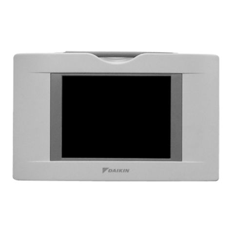
Wired remote controller
Operation Handbook
3P607381-5A
EM20A034
Read this Manual Before Using the Product
• This manual describes the basic operation of the indoor unit which uses the BRC1H62W/BRC1H62K
remote controller. Keep this manual where it is readily accessible, and refer to it when necessary.
• For detailed contents, refer to the BRC1H62W/BRC1H62K operation manual on our website.
Also, for explanation about things other than remote controller operation, refer to the operation
manual attached to the indoor unit.
Button Locations and Descriptions
The current status is displayed with icons.
About Icons on the Information Screen
The items displayed vary depending on the indoor unit you are using.
Icon Name Description
Information Indicates an information screen.
MAIN/SUB remote
controller
Displayed when used as the MAIN/SUB remote controller.
1=main, 2=sub
Bluetooth* Indicates that the controller is communicating with a mobile device,
for use with the app.
Setback Indicates that the indoor unit is operating under setback conditions.
A function to keep the room comfortable when the a/c is off by automatically
turning on the unit when the temperature exceeds setback setpoint.
Centralized Control Indicates that the system is controlled by central control equipment
(optional accessory) and that control of the system by the controller
is limited.
Changeover Under
Control (VRV only)
Displayed:
The remote controller does not have master control.
Unable to select heating/cooling operation.
* Immediately after the start of operation, this icon may not be
displayed on the information screen even if the remote controller
does not have master control. If you want to check if the remote
controller has master control, confirm on the home screen.
Blinking:
None of the remote controllers in the system have master control.
Can be set as the master controller during this time.
Not Displayed:
The remote controller has master control.
Able to select heating/cooling operation.
Backup Indicates that backup operation is being carried out.
Energy savings Indicates that the system’s energy consumption is being limited,
and that it is running with restricted capacity.
Test operation Indicates that Test Operation mode is active.
Defrost/Hot start Indicates that the defrost/hot start mode is active.
Self-cleaning filter
operation
Indicates that selfcleaning filter operation is active.
24-hour ventilation
Indicates that 24-hour ventilation is set.
* May not be displayed even if connected to a unit with this function.
Night purge Indicates that night purge is set.
Ventilating standby Indicates that ventilating operation has been stopped temporarily.
(In order to reduce energy loss, ventilating operation is stopped
immediately after cooling or heating operation starts).
Ventilating operation Indicates that ventilating operation is being carried out even when
operation is stopped, if 24-hour ventilation and night purge are set.
Pre Vent (Fresh-up)
Indicates that ventilating is being carried out powerfully due to a
large difference in the incoming airflow rate and exhaust airflow rate.
Warning Indicates that an error occurred, or that an indoor unit component
needs to be maintained.
* The Bluetooth® word mark and logos are registered trademarks owned by the Bluetooth SIG, Inc. and
use of such marks by Daikin industries, LTD. is under license. Other trademarks and trade names are
those of their respective owners.
Also refer to installation manual attached to the indoor unit.
Please read these “Safety Precautions” carefully before installing the remote controller.
• This manual classies the precautions into WARNINGS and CAUTIONS.
Be sure to follow all the precautions below: They are all important for ensuring safety.
WARNING Indicates a potentially hazardous situation which, if not avoided, could
result in death or serious injury.
CAUTION
Indicates a potentially hazardous situation which, if not avoided, may
result in minor or moderate injury.
It may also be used to alert against unsafe practices.
• After completing installation, conduct a test operation to check for faults and explain to the customer
how to operate the remote controller and cleaning of it with the aid of the operation manual. Ask the
customer to store the installation manual along with the operation manual for future reference.
WARNING
Ask your dealer or qualied personnel to carry out installation work.
Do not attempt to install the remote controller yourself.
Improper installation may result in electric shocks or a re.
Consult your local dealer regarding relocation and reinstallation of the remote controller.
Improper installation may result in electric shocks or a re.
Install the remote controller in accordance with the instructions in this installation manual.
Improper installation may result in electric shocks or a re.
Be sure to use only the specied accessories and parts for installation work.
Failure to use the specied parts may result in the remote controller falling down, electric shocks or a
re.
Install the remote controller on a foundation that can withstand its mass.
Insufcient strength may result in the remote controller falling down and causing injury.
Make certain that all electrical work is carried out by qualied personnel according to the applicable
legislation (note 1) and this installation manual, using a separate circuit.
In addition, even if the wiring is short, make sure to use a wiring that has sufcient length and never
connect additional wiring to make the length sufcient.
Insufcient capacity of the power supply circuit or improper electrical construction may lead to
electric shocks or a re.
(note 1) applicable legislation means “All international, national and local directives, laws, regulations
and/or codes which are relevant and applicable for a certain product or domain”.
Turn off the power before performing installation work.
Touching live parts may cause electric shocks.
Do not disassembly, reconstruct or repair.
Failure to do so many cause electric shock or a re.
Make sure that all wiring is secured, using the specied wirings and ensuring that external forces do
not act on the terminal connections or wirings.
Improper connections or xing may cause an overheat or a re.
The choice of materials and installations must comply with the applicable national and international
standards.
CAUTION
To avoid electric shocks due to entry of water or insects, ll the wiring through hole with putty.
Do not operate with wet hands to avoid electric shocks.
Do not wash the remote controller with water.
Failure to do so many cause electric shock or a re.
Install the air conditioner, power supply wiring, remote controller wiring and transmission wiring at
least 1 meter away from televisions or radios to prevent image interference or noise.
(Depending on the radio waves, a distance of 1meter may not be sufcient to eliminate the noise.)
Do not install the remote controller in the following locations:
1. Where there is oil mist, oil spray or vapour for example a kitchen.
Resin parts may deteriorate and fall off.
2. Where corrosive gas, such as sulphurous acid gas, is produced.
3. Where there is machinery which emits electromagnetic waves.
Electromagnetic waves may disturb the control system, and cause a malfunction of the
equipment.
4. Where ammable gas may leak, where there is carbon bre or ignitable dust suspensions in
the air, or where volatile ammables such as thinner or gasoline are handled.
Operating the unit in such conditions may result in a re.
5. High temperature area or near a heat source.
It may cause an overheat or a re.
6. Moist area, or place where may be exposed to water.
If water enters inside of the remote controller, electrical components may fail.
It may result in electric shocks or a re.
When remote controller’s thermostat sensor is used, select the installation location by considering
the followings.
• A place where average temperature in the room can be detected.
• A place where is not exposed to direct sunlight.
• A place where is far apart from heat source.
• A place where is not affected by outdoor air due to door opening/closing or the like.
Maintaining the Unit and LCD Display
•
Wipe the LCD and surface of the remote controller with a dry cloth when they become dirty.
•
If the dirt on the surface cannot be removed, soak the cloth in neutral detergent diluted with
water, squeeze the cloth tightly, and clean the surface. Wipe the surface with a dry cloth.
• Do not use non-neutral detergents or organic solvents (alcohol disinfectant, benzene,
paint thinner, etc.).
May cause cracking, electric shocks or re.
NOTICE
Do not use any paint thinner, organic solvent, or strong acid.
English
+
-
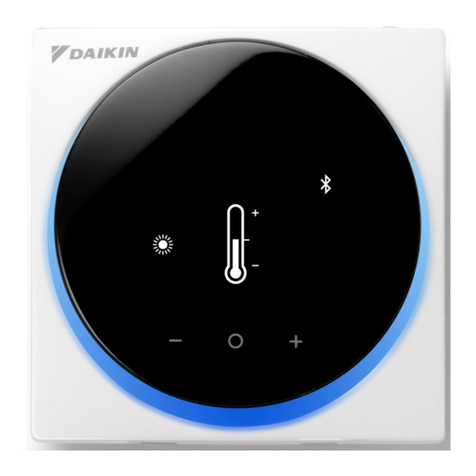
MODEL: BRC1H62W/BRC1H62K
SELECT/ACTIVATE/SET button
From the home screen, enter the main menu.
From the main menu, enter one of the submenus.
From their respective submenu, activate an operation/ventilation mode.
ON/OFF button
Press this button to turn
on the system.
Press this button again to
turn o the system.
NAVIGATE/ADJUST button
Navigate right.
Adjust a setting.
NAVIGATE/ADJUST button
Navigate left.
Adjust a setting.
Status indicator (LED)
During operation, the light
ring around the display
lights up blue/red/green.
Lights up blue: Operating,
Blinks red: Error is occurring,
Lights up/blinks green:
Bluetooth connecting
LCD
01_EN_3P607381-5A.indd 1 2021/06/24 15:33:52

