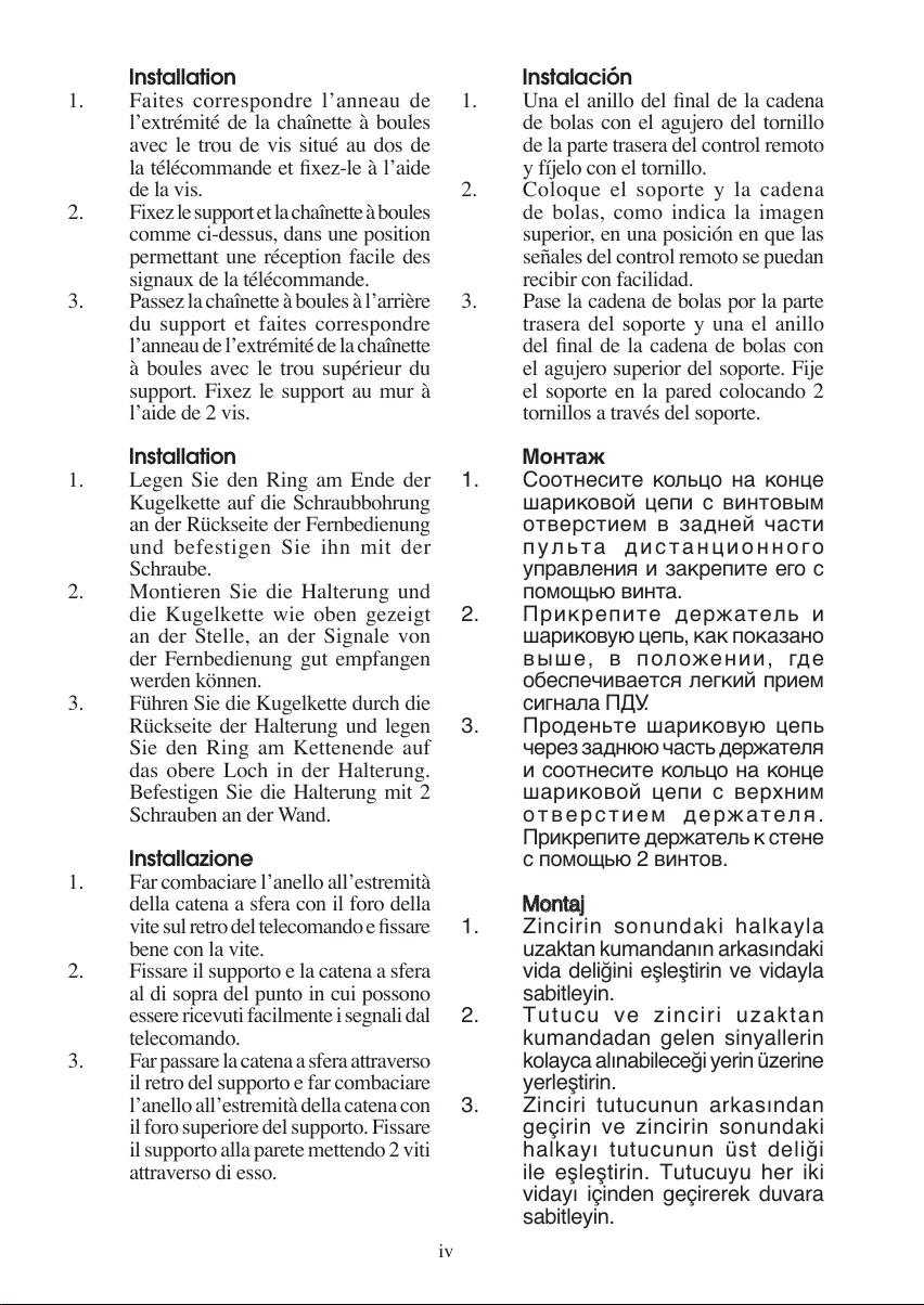
Daikin FTXB60C User manual

Руководство По Зксплуатации
Беспроводное Дистанционное Управление
Manuale Di Funzionamento
Ricevitore senza fili
Türkçe
Kullanım Kılavuzu
Kablosuz Kumanda
English
Operating Manual
Handset Wireless
Français
Deutsch
Italiano
Español
Pycckий
Mode D’emploi
Combiné sans fil
Bedienungsanleitung
Drahtloses Handgerät
Manual De Instrucciones
Auricular Inalámbrico
TURBO
QUIET SLEEP
MODE
TIMER
CANCEL
ON OFF
SWING FAN
CANCEL
CLOCK
OPERATING
MANUAL
OM-GS02-1011(4)-DAIKIN
Part No.: R08019037090D
CVR-OM-GS02-1011(4)DAIKIN-EN.ind1 1CVR-OM-GS02-1011(4)DAIKIN-EN.ind1 1 4/28/14 1:43:13 PM4/28/14 1:43:13 PM

i
TURBO
QUIET SLEEP
MODE
TIMER
CANCEL
ON OFF
SWING FAN
CANCEL
CLOCK
3
5
12
7
11
9
6
1
2
4
8
10
13
BRC52A61/62/63 Remote Control Indication
Indication De Télécommande BRC52A61/62/63
BRC52A61/62/63-Fernbedienungsanzeige
Indicazioni Telecomando BRC52A61/62/63
Indicación Del Mando A Distancia BRC52A61/62/63
Индикация пульта дистанционного управления BRC52A61/62/63
BRC52A61/62/63 UzaktanBRC52A61/62/63 Uzaktan Kumanda GöstergeleriKumanda Göstergeleri
CVR-OM-GS02-1011(4)DAIKIN-EN.ind2 2CVR-OM-GS02-1011(4)DAIKIN-EN.ind2 2 4/28/14 1:43:14 PM4/28/14 1:43:14 PM

ii
TURBO
QUIET SLEEP
MODE
TIMER
CANCEL
ON OFF
SWING FAN
CANCEL
CLOCK
TURBO
QUIET SLEEP
MODE
TIMER
CANCEL
ON OFF
SWING FAN
CANCEL
CLOCK
21
3
R03 / AAA 1.5V
R03 / AAA 1.5V
Remove batteries if the air conditioner
is not in use for a long period of time.
Use 2 "AAA" 1.5V Batteries.
HOW TO MOUNT ONTO THE WALL / COMMENT INSTALLER SUR LE
MUR / ANBRINGEN DER FERNSTEUERUNG AN DER WAND / COME
FISSARE L’ASTUCCIO DEL TELECOMANDO ALLA PARETE / MONTAJE
SOBRE LA PARED / КАК УСТАНОВИТЬ НА СТЕНУ / DUVARA NASILDUVARA NASIL
YERLEfiT‹R‹L‹RYERLEfiT‹R‹L‹R
TO INSERT BATTERIES (AAA.R03) / INTRODUIRE LES PILES (AAA.R03) /
EINSETZEN DER BATTERIEN (AAA.R03)/ INSERIMENTO DELLE BATTERIE
(AAA.R03) / INSERTE LAS PILAS (AAA.R03) / УСТАНОВКА БАТАРЕЙ
(AAA.R03) / P‹LLER NASIL TAKILIR (AAA.R03)P‹LLER NASIL TAKILIR (AAA.R03)
CVR-OM-GS02-1011(4)DAIKIN-EN.ind3 3CVR-OM-GS02-1011(4)DAIKIN-EN.ind3 3 4/28/14 1:43:14 PM4/28/14 1:43:14 PM

iii
Installation
Match the ring at the end of the ball chain with the screw hole on the back of the remote
controller and secure it with the screw.
Attach the holder and the ball chain as above at the position where signals from the
remote controller can be received easily.
Pass the ball chain through the back of the holder and match the ring at the end of the
ball chain to the upper hole of the holder. Fix the holder to the wall by putting through
2 screws across it.
1.
2.
3.
REMOTE CONTROLLER LOSS PREVENTION WITH BALL CHAIN (OPTIONAL) /
PRÉVENTION CONTRE LA PERTE DE LA TÉLÉCOMMANDE PAR CHAÎNETTE À
BOULES (FACULTATIF) / DIE FERNBEDIENUNG IST DURCH EINE KUGELKETTE VOR
VERLUST GESICHERT (OPTIONAL) / PREVENZIONE PERDITA TELECOMANDO
CONCATENA ASFERA(OPZIONALE)/PREVENCIÓNDEPÉRDIDADELCONTROL
REMOTO CON CADENA DE BOLAS (OPCIONAL) / ПРЕДОТВРАЩЕНИЕ
ПОТЕРИ ПДУ С ПОМОЩЬЮ ШАРИКОВОЙ ЦЕПИ (ДОПОЛНИТЕЛЬНОЕ
ОБОРУДОВАНИЕ) / Z‹NC‹RLE UZAKTAN KUMANDANIN KAYBOLMASININZ‹NC‹RLE UZAKTAN KUMANDANIN KAYBOLMASININ
ÖNLENMES‹ (‹STE⁄E BA⁄LI)ÖNLENMES‹ (‹STE⁄E BA⁄LI)
Remote controller
Télécommande
Fernbedienung
Telecomando
Control Remoto
Пульт дистанционного управления
Uzaktan kumanda
Screw
Vis
Schraube
Vite
Tornillo
Винт
Vida
Wall attachment screw
Vis de fixation murale
Schraube für Wandbefestigung
Vite fissaggio a parete
Tornillo de instalación en pared
Винт настенного крепления
Duvar ba¤lant› vidas›
Holder
Support
Halterung
Supporto
Soporte
Держатель
Tutucu
Ball chain (350mm)
Chaînette à boules (350mm)
Kugelkette (350mm)
Catena a sfera (350mm)
Cadena de bolas (350mm)
Шариковая цепь (350мм)
Zincir (350mm)
CVR-OM-GS02-1011(4)DAIKIN-EN.ind4 4CVR-OM-GS02-1011(4)DAIKIN-EN.ind4 4 4/28/14 1:43:14 PM4/28/14 1:43:14 PM


iv
Installation
Faites correspondre l’anneau de
l’extrémité de la chaînette à boules
avec le trou de vis situé au dos de
la télécommande et fixez-le à l’aide
de la vis.
Fixez le support et la chaînette à boules
comme ci-dessus, dans une position
permettant une réception facile des
signaux de la télécommande.
Passez la chaînette à boules à l’arrière
du support et faites correspondre
l’anneau de l’extrémité de la chaînette
à boules avec le trou supérieur du
support. Fixez le support au mur à
l’aide de 2 vis.
Installation
Legen Sie den Ring am Ende der
Kugelkette auf die Schraubbohrung
an der Rückseite der Fernbedienung
und befestigen Sie ihn mit der
Schraube.
Montieren Sie die Halterung und
die Kugelkette wie oben gezeigt
an der Stelle, an der Signale von
der Fernbedienung gut empfangen
werden können.
Führen Sie die Kugelkette durch die
Rückseite der Halterung und legen
Sie den Ring am Kettenende auf
das obere Loch in der Halterung.
Befestigen Sie die Halterung mit 2
Schrauben an der Wand.
Installazione
Far combaciare l’anello all’estremità
della catena a sfera con il foro della
vite sul retro del telecomando e fissare
bene con la vite.
Fissare il supporto e la catena a sfera
al di sopra del punto in cui possono
essere ricevuti facilmente i segnali dal
telecomando.
Far passare la catena a sfera attraverso
il retro del supporto e far combaciare
l’anello all’estremità della catena con
il foro superiore del supporto. Fissare
il supporto alla parete mettendo 2 viti
attraverso di esso.
1.
2.
3.
1.
2.
3.
1.
2.
3.
Instalación
Una el anillo del final de la cadena
de bolas con el agujero del tornillo
de la parte trasera del control remoto
y fíjelo con el tornillo.
Coloque el soporte y la cadena
de bolas, como indica la imagen
superior, en una posición en que las
señales del control remoto se puedan
recibir con facilidad.
Pase la cadena de bolas por la parte
trasera del soporte y una el anillo
del final de la cadena de bolas con
el agujero superior del soporte. Fije
el soporte en la pared colocando 2
tornillos a través del soporte.
Монтаж
Соотнесите кольцо на конце
шариковой цепи с винтовым
отверстием в задней части
пульта дистанционного
управления и закрепите его с
помощью винта.
Прикрепите держатель и
шариковую цепь, как показано
выше, в положении, где
обеспечивается легкий прием
сигнала ПДУ.
Проденьте шариковую цепь
через заднюю часть держателя
и соотнесите кольцо на конце
шариковой цепи с верхним
отверстием держателя.
Прикрепите держатель к стене
с помощью 2 винтов.
MontajMontaj
Zincirin sonundaki halkayla
uzaktan kumandan›n arkas›ndaki
vida deli¤ini efllefltirin ve vidayla
sabitleyin.
Tutucu ve zinciri uzaktan
kumandadan gelen sinyallerin
kolayca al›nabilece¤i yerin üzerine
yerlefltirin.
Zinciri tutucunun arkas›ndan
geçirin ve zincirin sonundaki
halkay› tutucunun üst deli¤i
ile efllefltirin. Tutucuyu her iki
viday› içinden geçirerek duvara
sabitleyin.
1.
2.
3.
1.
2.
3.
1.
2.
3.
CVR-OM-GS02-1011(4)DAIKIN-EN.ind5 5CVR-OM-GS02-1011(4)DAIKIN-EN.ind5 5 4/28/14 1:43:14 PM4/28/14 1:43:14 PM

v
CVR-OM-GS02-1011(4)DAIKIN-EN.ind6 6CVR-OM-GS02-1011(4)DAIKIN-EN.ind6 6 4/28/14 1:43:14 PM4/28/14 1:43:14 PM

ENGLISH
1
OPERATING GUIDE
Transmission source
The source where the signal will be transmitted.
Signal transmission indication
Blink to confirm that the last setting has been transmitted to the unit.
“ON/OFF” Button
Press once to start the air conditioner unit.
Press again to stop the unit.
Fan speed selection
Pressing the button continuously will toggle the fan speed in the following
order:
Low Med High Auto
Stop pressing when the desired fan speed appears on the display screen.
Operation mode
Press the MODE button to select the type of operating mode.
For cooling only unit, the available modes are: COOL ( ), DRY ( ) and FAN ( ).
For heat pump unit, the available modes are: AUTO ( ), COOL ( ), DRY ( ),
FAN ( ) and HEAT ( ).
The AUTO ( ) mode is unavailable for chilled water system except 4-pipe
system.
Automatic air swing
Press the SWING button to activate the automatic air swing function.
To distribute the air to a specific direction, press the SWING button and wait
until the louver move to the desired direction and press the button once again.
Swing mode selection method (model dependent)
Press SWING ( )button for 4 seconds to enter field setting mode. While in field
setting mode, it will only show SWING MODE ( ).
Press temperature and button to select SWING MODE ( )rotation from
Swing Mode 1 to Swing Mode 3.
There are 3 different SWING MODE, which are:
Swing mode 1 Swing mode 2 Swing mode 3
SWING MODE will not activate unless SWING is activated.
Swing is indicated by the logo:
If no mode changes within 4 seconds, unit will operate according to the selected
SWING MODE ( ).
Turbo function (model dependent)
Press for fast cooling or heating operation.
Fan speed turn to maximum speed.
Press again to deactivate the function.
Available under HEAT and COOL modes only.
Any change of fan speed will deactivate this function.
1.
•
2.
•
3.
•
•
4.
•
•
5.
•
•
•
•
6.
•
•
•
•
•
•
7.
•
•
•
•
•
Original Instruction
1-OM-GS02-1011(4)DAIKIN-EN.indd Sec1:11-OM-GS02-1011(4)DAIKIN-EN.indd Sec1:1 4/28/14 3:25:07 PM4/28/14 3:25:07 PM

2
+2 C
+1 C
- 1 C
- 2 C
0 0.5 1 1.5 2
- 3 C
OFF timer setting
Press the OFF TIMER button will activate the off timer function.
Set the desired off time by pressing the OFF TIMER button continuously.
Press the CANCEL button to cancel the off timer setting.
Quiet function (model dependent)
Press for quiet operation.
Fan speed turn to minimum speed.
Press again to deactivate the function.
Available under HEAT and COOL modes only.
Any change of fan speed will deactivate this function.
Clock time setting
Press and hold button to set the clock time.
ON timer setting
Press the ON TIMER button will activate the on timer function.
Set the desired on time by pressing the ON TIMER button continuously. If the
timer is set to 7.30am, the air conditioner will turn on at 7.30am sharp.
Press the CANCEL button to cancel the on timer setting.
Sleep mode setting
Press the button will activate the sleep mode function.
This is an energy saving option. When the unit is operating under cooling mode,
the set temperature is increased by 0.5°C after
the first half an hour, another 0.5°C after the
second half an hour and 1°C after the following
1 hour.
When the unit is operating under heating
mode, the set temperature is decreased by
1°C after the first half an hour, another 1°C
after the second half an hour and 1°C after the
following 1 hour.
This function is available under COOL,
HEAT and AUTO mode.
Temperature setting
To set the desired room temperature, press the or button to increase or
decrease the set temperature.
The temperature setting range is from 16°C to 30°C (Optional setting 20°C to
30°C).
Press both buttons and simultaneously to toggle from °C to °F setting.
8.
•
•
•
9.
•
•
•
•
•
10.
•
11.
•
•
•
12.
•
•
•
•
13.
•
•
•
1-OM-GS02-1011(4)DAIKIN-EN.indd Sec1:21-OM-GS02-1011(4)DAIKIN-EN.indd Sec1:2 4/28/14 3:25:08 PM4/28/14 3:25:08 PM

ENGLISH
3
FAULT DIAGNOSIS BY REMOTE CONTROLLER
The temperature display sections indicate corresponding codes.
When the ON TIMER CANCEL button or OFF TIMER CANCEL button is held down for 5
seconds, a “ ” indication flashes on the temperature display section.
Press the ON TIMER CANCEL button or OFF TIMER CANCEL button repeatedly until a
continuous beep is produced.
The code indication changes as shown below, and notifies with a long beep.
1.
2.
•
TURBO
QUIET SLEEP
MODE
TIMER
CANCEL
ON OFF
SWING FAN
CANCEL
CLOCK
FAULT DIAGNOSIS (For Inverter only)
ON TIMER CANCEL
OFF TIMER CANCEL
ERROR CODE MEANING
00 NORMAL
A1 INDOOR PCB ERROR
A3 DRAIN PUMP ABNORMAL
A5 ANTIFREEZE (COOLING)/HEAT EXCHANGER OVERHEAT (HEATING)
A6 INDOOR FAN MOTOR ABNORMAL
AH ELECTRICAL AIR CLEANER ABNORMAL
C4 INDOOR HEAT EXCHANGER (1) THERMISTOR SHORT/OPEN
C5 INDOOR HEAT EXCHANGER (2) THERMISTOR SHORT/OPEN
C7 LOUVER LIMIT SWITCH ERROR
C9 INDOOR ROOM THERMISTOR SHORT/OPEN
E1 OUTDOOR PCB ERROR
E3 HIGH PRESSURE PROTECTION
E4 LOW PRESSURE PROTECTION
E5 COMPRESSOR MOTOR LOCK/COMPRESSOR OVERLOADED
E6 COMPRESSOR START-UP ERROR
E7 OUTDOOR DC FAN MOTOR LOCK
E8 AC INPUT OVER CURRENT
E9 EXV ERROR
EA 4 WAY VALVE ERROR
F3 DISCHARGE PIPE OVERHEAT
F6 HEAT EXCHANGER OVERHEAT
HO COMPRESSOR SENSOR SYSTEM ERROR
H3 HIGH PRESSURE SWITCH ERROR
H6 COMPRESSOR FEEDBACK DETECTION ERROR
H7 FAN MOTOR OVERLOADED/OVERCURRENT/SENSOR ABNORMAL
H8 AC CURRENT SENSOR ERROR
1-OM-GS02-1011(4)DAIKIN-EN.indd Sec1:31-OM-GS02-1011(4)DAIKIN-EN.indd Sec1:3 4/28/14 3:25:08 PM4/28/14 3:25:08 PM


4
1. A short beep and two consecutive beeps indicate non-corresponding codes.
2. To cancel the code display, hold the ON TIMER CANCELbutton or OFFTIMER CANCELbutton
down for 5 seconds. The code display also cancel itself if the button is not pressed for 1 minute.
NOTE
ERROR CODE MEANING
H9 OUTDOOR AIR THERMISTOR SHORT/OPEN
J1 PRESSURE SENSOR ERROR
J3 COMPRESSOR DISCHARGE PIPE THERMISTOR SHORT/OPEN/MISPLACED
J5 SUCTION PIPE THERMISTOR SHORT/OPEN
J6 OUTDOOR HEAT EXCHANGER THERMISTOR SHORT/OPEN
J7 SUBCOOLING HEAT EXCHANGER THERMISTOR SHORT/OPEN
J8 LIQUID PIPE THERMISTOR SHORT/OPEN
J9 GAS PIPE THERMISTOR SHORT/OPEN
L1 INVERTER OUTDOOR PCB ERROR
L3 OUTDOOR CONTROL BOX OVERHEAT
L4 HEAT SINK OVERHEAT
L5 IPM ERROR/IGBT ERROR
L8 INVERTER COMPRESSOR OVERCURRENT
L9 COMPRESSOR OVERCURRENT PREVENTION
LC COMMUNICATION ERROR (OUTDOOR CONTROL PCB AND INVERTER PCB)
P1 OPEN PHASE OR VOLTAGE UNBALANCE
P4 HEAT SINK THERMISTOR SHORT/OPEN
PJ CAPACITY SETTING ERROR
U0 INSUFFICIENT GAS
U2 DC VOLTAGE OUT OF RANGE
U4 COMMUNICATION ERROR
U7 COMMUNICATION ERROR (OUTDOOR CONTROL PCB AND IPM PCB)
UA INSTALLATION ERROR
UF
PIPING & WIRING INSTALLATION MISMATCH/WRONG WIRING/INSUFFICIENT GAS
UH ANTIFREEZE (OTHER ROOMS)
1-OM-GS02-1011(4)DAIKIN-EN.indd Sec1:41-OM-GS02-1011(4)DAIKIN-EN.indd Sec1:4 4/28/14 3:25:09 PM4/28/14 3:25:09 PM

1
MODE D’EMPLOI
Source de transmission
La source d’où le signal sera transmis.
Indication de transmission de signal
Clignotement pour confirmer que le dernier réglage ait été transmis à l’unité.
Bouton « ON/OFF » (MARCHE’/ARRÊT)
Appuyez une fois pour mettre le climatiseur en marche.
Appuyez de nouveau pour éteindre le climatisateur.
Sélection de la vitesse du ventilateur
Appuyez de façon continue sur le bouton pour transformer successivement la vitesse du ventilateur
comme suit:
Lent Moyen Rapide Auto
Cessez d’appuyer lorsque la vitesse désirée apparaît sur l’écran d’affichage.
Mode opérationnel
Appuyez sur le bouton MODE pour sélectionner le type de mode opérationnel.
Pour l’unité de refroidissement, les modes disponibles comprennent COOL ( ) (FROID), DRY ( )
(SEC) et FAN ( ) (VENTILATION).
Pour l’unité de thermopompe, les modes disponibles comprennent: AUTO ( ) (AUTO), COOL ( )
(FROID), DRY ( ) (SEC), FAN ( ) (VENTILATION) et HEAT ( ) (CHAUD).
Le mode AUTO ( )n’est pas disponible pour le système à eau glacée à l’exception du système
à 4 conduites.
Oscillation automatique de la ventilation
Appuyez sur le bouton SWING pour activer la fonction d’oscillation automatique de la ventilation.
Pour orienter la ventilation dans une direction précise, appuyez sur le bouton SWING , attendez ensuite
que le volet de ventilation souffle dans la direction désirée puis appuyez de nouveau sur le bouton.
Méthode de sélection du mode Swing (dépendant du modèle)
Appuyez sur le bouton SWING ( )pendant 4 secondes pour entrer dans le mode de réglage du champ.
En mode de réglage local, seul le mode d’oscillation SWING MODE ( )est affiché.
Appuyez sur le bouton de température et pour sélectionner la rotation du SWING MODE ( )
depuis le Mode Swing 1 au Mode Swing 3.
Les 3 différents modes d’oscillation (SWING MODE) suivants sont disponibles :
Mode d’oscillation 1 Mode d’oscillation 2 Mode d’oscillation 3
Le mode d’oscillation (SWING MODE) ne sera pas activé, sauf si la fonction d’oscillation (SWING)
est activée.
L’oscillation est indiquée par le logo :
Si aucun mode ne change dans les 4 secondes, l’appareil fonctionnera selon le SWING MODE ( )
sélectionné.
Fonction turbo (dépendant du modèle)
Appuyez sur le bouton pour refroidissement ou réchauffement rapide.
Le ventilateur tourne à sa vitesse maximale.
Pressez de nouveau pour désactiver la fonction.
Disponible seulement sur le mode HEAT (CHAUD) et COOL (FROID).
Toute modification de la vitesse du ventilateur entraîne l’arrêt de cette fonction.
1.
•
2.
•
3.
•
•
4.
•
•
5.
•
•
•
•
6.
•
•
•
•
•
•
7.
•
•
•
•
•
Traduction des instructions d’origine
FRANÇAIS
2-OM-GS02-1011(4)DAIKIN-FR.indd Sec1:12-OM-GS02-1011(4)DAIKIN-FR.indd Sec1:1 4/8/14 11:41:13 AM4/8/14 11:41:13 AM

2
+2 C
+1 C
- 1 C
- 2 C
0 0,5 1 1,5 2
- 3 C
Programmer la minuterie d’arrêt
Appuyez sur le bouton OFF TIMER pour activer la minuterie d’arrêt.
Programmez l’heure désirée en appuyant continuellement sur le bouton OFF TIMER.
Appuyez sur le bouton CANCEL pour annuler le programmation d’arrêt.
Fonction silence (dépendant du modèle)
Appuyez sur pour un fonctionnement silencieux.
Le ventilateur tourne à sa vitesse minimale.
Pressez de nouveau pour désactiver la fonction.
Disponible seulement sur le mode HEAT (CHAUD) et COOL (FROID).
Toute modification de la vitesse du ventilateur entraîne l’arrêt de cette fonction.
Mettre l’horloge à l’heure
Maintenez le bouton enfoncé pour mettre l’horloge à l’heure.
Programmer la minuterie de mise en marche
Appuyez sur le bouton ON TIMER pour activer la minuterie de mise en marche.
Programmez l’heure désirée en appuyant continuellement sur le bouton ON TIMER. Si la minuterie est
programmée à 7h30, le climatiseur se mettra en marche à 7h30 pile.
Appuyez sur le bouton CANCEL pour annuler le programmation de la minuterie.
Réglage du mode de nuit
Appuyez sur le bouton pour activer la fonction de mode de nuit.
Ceci est une option anti-gaspillage d’énergie. Lorsque l’unité fonctionne en mode de refroidissement, la
température réglée augmente de 0,5°C au bout de la première
demi-heure, d’encore 0,5°C au bout de la deuxième demi-
heure et d’1°C au bout de l’heure suivante.
Lorsque l’unité fonctionne en mode de chauffage, la
température réglée diminue d’1°C au bout de la première
demi-heure, d’encore 1°C au bout de la deuxième
demiheure et d’1°C au bout de l’heure suivante.
Cette fonction est disponible en mode COOL (FROID),
HEAT (CHAUD) et AUTO (AUTO).
Réglage de la température
Pour régler la température au niveau que vous souhaitez,
appuyez sur le bouton ou pour l’augmenter ou la
baisser.
La température se régle de 16°C à 30°C (Possibilité de régler de 20°C à 30°C).
Appuyez sur les boutons et simultanément pour passer des °C aux °F et inversement.
8.
•
•
•
9.
•
•
•
•
•
10.
•
11.
•
•
•
12.
•
•
•
•
13.
•
•
•
2-OM-GS02-1011(4)DAIKIN-FR.indd Sec1:22-OM-GS02-1011(4)DAIKIN-FR.indd Sec1:2 4/8/14 11:41:14 AM4/8/14 11:41:14 AM

3
FAUX DIAGNOSTICS PAR LA TELECOMMANDE
La partie d’affichage de la température indique les codes correspondants.
Lorsque le boutonAnnuler de la mise en marche par minuterie ONTIMER CANCEL(ANNULER LAMISE
À L’ARRÊT PAR MINUTERIE) ou le bouton de la mise à l’arrêt par minuterie OFF TIMER CANCEL
(ANNULER LA MISE EN MARCHE PAR MINUTERIE) est enfoncé pendant 5 secondes, un signe “ ”
clignote sur la partie d’affichage de la température.
Appuyez sur le bouton ON TIMER CANCEL (ANNULER LA MISE EN MARCHE PAR MINUTERIE)
ou OFF TIMER CANCEL (ANNULER LA MISE À L’ARRÊT PAR MINUTERIE) répétitivement jusqu’à
ce qu’un bip continu se produise.
L’indication du code change comme montré ci dessous, et notifie avec un long bip.
1.
2.
•
TURBO
QUIET SLEEP
MODE
TIMER
CANCEL
ON OFF
SWING FAN
CANCEL
CLOCK
FAU DAIGNOSTICS (pour modèle à inverseur seulement)
ON TIMER CANCEL
(ANNULER LA MISE EN
MARCHE PAR MINUTERIE)
CODE D’ERREUR SIGNIFICATION
00 NORMAL
A1 ERREUR PCB DANS LA SECTION INTÉRIEURE
A3 ANOMALIE DE LA POMPE DE VIDANGE
A5 ANTIGEL (REFROIDISSEMENT) / ÉCHANGEUR DE CHALEUR DE SURCHAUFFE(CHAUFFAGE)
A6 ANOMALIE SUR LE VENTILATEUR D’INTÉRIEUR
AH ANOMALIE DU FILTRE À AIR ÉLECTRIQUE
C4 THERMISTOR DE L'ÉCHANGEUR THERMIQUE INTÉRIEUR (1) EN COURT-CIRCUIT/OUVERT
C5 THERMISTOR DE L'ÉCHANGEUR THERMIQUE INTÉRIEUR (2) EN COURT-CIRCUIT/OUVERT
C7 ERREUR DE L’INTERRUPTEUR DE LIMITE D’AILETTE
C9 COURT-CIRCUIT/OUVERTURE DANS LE THERMISTOR DE PIÈCE INTÉRIEURE
E1 ERREUR DE CARTE EXTÉRIEURE
E3 PROTECTION HAUTE PRESSION
E4 PROTECTION BASSE PRESSION
E5 VERROU DU MOTEUR DU COMPRESSEUR /COMPRESSEUR SURCHARGÉ
E6 ERREUR DE DÉMARRAGE DU COMPRESSEUR
E7 VERROU DU MOTEUR DE VENTILATEUR CC EXTÉRIEUR
E8 SURINTENSITÉ D’ENTRÉE CA
E9 ERREUR EXV
EA ERREUR DE VANNE À 4 VOIES
F3 TUYAUTERIE DE VIDANGE DE SURCHAUFFE
F6 ÉCHANGEUR DE CHALEUR DE SURCHAUFFE
HO ERREUR DU SYSTÈME DE CAPTEUR DU COMPRESSEUR
H3 ERREUR DE L’INTERRUPTEUR HAUTE PRESSION
H6 ERREUR DE DÉTECTION DE L’ALIMENTATION DU COMPRESSEUR
H7 SURCHARGE/SURINTENSITÉ DU MOTEUR DU VENTILATEUR/ANOMALIE DU CAPTEUR
H8 ERREUR DU CAPTEUR DE COURANT CA
OFF TIMER CANCEL
(ANNULER LA MISE À
L’ARRÊT PAR MINUTERIE)
FRANÇAIS
2-OM-GS02-1011(4)DAIKIN-FR.indd Sec1:32-OM-GS02-1011(4)DAIKIN-FR.indd Sec1:3 4/8/14 11:41:14 AM4/8/14 11:41:14 AM

4
CODE D’ERREUR SIGNIFICATION
H9 THERMISTANCE À AIR EXTÉRIEUR EN COURT-CIRCUIT/OUVERT
J1 ERREUR DU CAPTEUR DE PRESSION
J3 THERMISTANCE DE LA TUYAUTERIE DE VIDANGE DU COMPRESSEUR EN COURT-CIRCUIT/
OUVERTE/ MAL POSITIONNÉE
J5 COURT-CIRCUIT/OUVERTURE DANS LE THERMISTOR DU TUYAU D’ASPIRATION
J6 THERMISTANCE D’ÉCHANGEUR DE CHALEUR EXTÉRIEUR EN COURT-CIRCUIT/OUVERT
J7 COURT-CIRCUIT/OUVERTURE DANS LE THERMISTOR DE L’ÉCHANGEUR THERMIQUE DE
SOUS- REFROIDISSEMENT
J8 THERMISTANCE DE LA TUYAUTERIE DU LIQUIDE EN COURT-CIRCUIT/OUVERTE
J9 THERMISTANCE DE LA TUYAUTERIE DE GAZ EN COURT-CIRCUIT/OUVERTE
L1 ERREUR PCB EXTÉRIEURE DE L’INVERSEUR
L3 BOÎTIER DE COMMANDE EXTÉRIEUR DE SURCHAUFFE
L4 DISSIPATEUR THERMIQUE DE SURCHAUFFE
L5 ERREUR IPM /ERREUR IGBT
L8 SURINTENSITÉ DU COMPRESSEUR DE L’INVERSEUR
L9 PRÉVENTION DE SURINTENSITÉ DU COMPRESSEUR
LC ERREUR DE COMMUNICATION (PCB DE LA COMMANDE EXTÉRIEURE ET PCB DE
L’INVERSEUR)
P1 PHASE OUVERTE OU DÉSÉQUILIBRE DE TENSION
P4 THERMISTANCE DE DISSIPATEUR DE CHALEUR EN COURT-CIRCUIT/OUVERT
PJ ERREUR DE RÉGLAGE DE LA CAPACITÉ
U0 INSUFFISANCE DE GAZ
U2 TENSION CC HORS PLAGE
U4 ERREUR DE COMMUNICATION
U7 ERREUR DE COMMUNICATION (CARTE DE COMMANDE ET CARTE IPM)
UA ERREUR D’INSTALLATION
UF MAUVAISE CORRESPONDANCE DANS L’INSTALLATION DU CÂBLAGE ET DE LA TUYAUTERIE/
MAUVAIS CÂBLAGE/INSUFFISANCE EN GAZ
UH ANTIGEL (AUTRES PIÈCES)
Un bip bref et deux bip consécutifs indique qu’il n’y a pas de codes correspondants.
Pour annuler l’affichage du code, appuyez pendant 5 secondes sur le bouton ON TIMER CANCEL (ANNULER
LA MISE EN MARCHE PAR MINUTERIE) ou OFF TIMER CANCEL (ANNULER LA MISE À L’ARRÊT PAR
MINUTERIE). Le code affiché s’annule lui même si le bouton n’est pas appuyé pendant 1 minute.
1.
2.
REMARQUE
2-OM-GS02-1011(4)DAIKIN-FR.indd Sec1:42-OM-GS02-1011(4)DAIKIN-FR.indd Sec1:4 4/8/14 11:41:14 AM4/8/14 11:41:14 AM


1
GEBRAUCHSANWEISUNG
Sendungsquelle
Die Ausgangsquelle des Signals.
Signalübertragungsanzeige
Blinkt auf, um anzuzeigen, dass das letzte Signal an das Gerät übertragen wurde.
“ON/OFF” („AN/AUS“) schalter
Einmal betätigen - das Gerät schaltet sich ein.
Nochmals betätigen - das Gerät schaltet sich aus.
Wahl der drehzahl-Stufe des kühlgebläses
Wird der Knopf kontinuierlich betätigt, dann ändert sich jeweils die Drehzahlstufe des Kühlgebläses
in dieser Reihenfolge:
Niedrig Mittel Hoch Automatisch
Den Knopf nicht weiter betätigen, wenn die gewünschte Drehzahlstufe des Kühlgebläses angezeigt
wird.
Betrieb
Zur Wahl der verschiedenen Arten des Betriebs wird der MODE Knopf betätigt.
Für die Kühlung kann man COOL( ) (KÜHL), DRY ( ) (TROCKEN) und FAN ( ) (GEBLÄSE)
wählen.
Für den Betrieb der Wärmepumpe hat man die Wahl zwischen: AUTO ( ), COOL ( ) (KÜHL),
DRY ( ) (TROCKEN), FAN ( ) (GEBLÄSE) und HEAT ( ) (WARM).
Der AUTO ( ) Modus steht für das Kaltwassersystem nicht zur Verfügung. Eine Ausnahme bildet
das 4-Rohr-System.
Automatische Luftschwingung
Durch Betätigen des SWING Knopfs wird die automatische Luftschwingungsfunktion aktiviert.
Damit die Luft in eine bestimmte Richtung bläst, wird der SWING Knopf betätigt, danach warten,
bis sich die Lüftungsschlitze in die gewünschte Richtung bewegen und dann den Knopf nochmals
betätigen.
Auswahlverfahren für Swing-Modus (von Model abhängig)
Drücken Sie die Taste SWING ( )für 4 Sekunden lang, um in das Feld des Einstellmodus zu gelangen.
Im Feldeinstellungsmodus erscheint nur die Meldung SWING MODE ( ).
Drücken Sie die Temperaturtaste und um die Drehzahl von SWING MODE ( )von Swing-
Modus 1 bis auf Swing-Modus 3 auszuwählen.
Folgende drei automatische Luftschwenkmodi (SWING MODE) stehen zur Verfügung:
Luftschwenkmodus 1 Luftschwenkmodus 2 Luftschwenkmodus 3
SWING MODE wird erst aktiviert, wenn SWING eingeschaltet ist.
Der Schwenkmodus wird durch dieses Logo angezeigt:
Falls sich keiner Modus innerhalb 4 Sekunden ändert, funktioniert das Gerät gemäß den ausgewählten
SWING MODE ( ).
Turbofunktion (von Model abhängig)
Zum schnellen Kühlen oder Erwärmen die Taste betätigen.
Gebläsedrehzahl wird auf Höchstgeachwindigkeit gebracht.
Drücken Sie erneut, um diese Funktion zu deaktivieren.
Erhältlich nur für HEAT (WÄRME) und COOL (KÜHL) betrieb.
Die Funktion wird durch eine Veränderung der Gebläsedrehzahl ausgeschaltet.
1. •
2. •
3. •
•
4. •
•
5. •
•
•
•
6. •
•
•
•
•
•
7. •
•
•
•
•
Übersetzung der Original-Anleitungen
DEUTSCH
3-OM-GS02-1011(4)DAIKIN-DE.indd Sec1:13-OM-GS02-1011(4)DAIKIN-DE.indd Sec1:1 4/8/14 11:44:48 AM4/8/14 11:44:48 AM

2
AUS - Zeitschalter-einstellung
Die Funktion des AUS - Zeitschalters wird durch Betätigen des OFF TIMER -Knopfes aktiviert.
Den OFF TIMER -Knopf solange betätigen, bis die gewünschte Ausschaltungszeit angezeigt und
somit eingestellt ist.
Zum Löschen der Einstellung des AUS - Zeitschalters wird der CANCEL Knopf betätigt.
Ruhefunktion (von Model abhängig)
Für leisen Betrieb drücken.
Gebläsedrehzahl wird auf Mindestgeschwindigkeit gebracht.
Drücken Sie erneut, um diese Funktion zu deaktivieren.
Erhältlich nur für HEAT (WÄRME) und COOL (KÜHL) betrieb.
Die Funktion wird durch eine Veränderung der Gebläsedrehzahl ausgeschaltet.
Einstellen der Uhrzeit
Drücken Sie zur Einstellung der Uhrzeit die -Taste und halten Sie sie gedrückt.
EIN - Zeitschalter-einstellung
Die Funktion des EIN - Zeitschalters wird durch Betätigen des ON TIMER -Knopfes aktiviert.
Den ON TIMER -Knopf solange betätigen, bis die gewünschte Zeit angezeigt und somit eingestellt
wird. Ist der Zeitschalter auf 7.30 Uhr eingestellt, so schaltet sich die Klimaanlage genau um diese
Zeit ein.
Zum Löschen der Einstellung des EIN - Zeitschalters wird der CANCEL Knopf betätigt.
Einstellen des Nachtbetriebs
Durch Betätigen des Knopfs wird der Nachtbetrieb aktiviert.
Dabei kann man Energie sparen. Befindet sich das Gerät im Kühlmodus, steigt die eingestellteTemperatur
nach der ersten halben Stunde um 0,5°C. Nach der zweiten
halben Stunde steigt die Temperatur um weitere 0,5°C und
um 1°C nach der folgenden Stunde.
Befindet sich das Gerät im Heizmodus, sinkt die
eingestellte Temperatur nach der ersten halben Stunde
um 1°C. Nach der zweiten halben Stunde sinkt die
Temperatur um weitere 1°C und um 1°C nach der
folgenden Stunde.
Diese Funktion gibt es bei COOL (KÜHL), HEAT
(WARM) und AUTO (AUTO) Betrieb.
Temperatureinstellung
Um die gewünschte Temperatur einzustellen, den oder
den Knopf betätigen, so wird die eingestellte Temperatur höher oder niedriger gestellt.
Der Temperatur-Einstellbereich liegt zwischen 16°C zu 30°C (Die optimale Einstellung liegt zwischen
20°C zu 30°C).
Drücken Sie gleichzeitig die Tasten und , um von °C auf °F umzustellen.
8. •
•
•
9. •
•
•
•
•
10. •
11. •
•
•
12. •
•
•
•
13. •
•
•
+2 C
+1 C
- 1 C
- 2 C
0 0,5 1 1,5 2
- 3 C
3-OM-GS02-1011(4)DAIKIN-DE.indd Sec1:23-OM-GS02-1011(4)DAIKIN-DE.indd Sec1:2 4/8/14 11:44:49 AM4/8/14 11:44:49 AM
This manual suits for next models
4
Table of contents
Languages:
Other Daikin Handset manuals