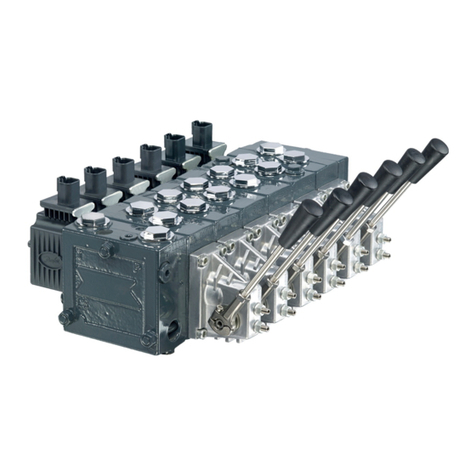
PVG 120 service parts exploded view
PVG 120 sectional view
Safety in application Control system example................................................................................................................................................................8
Examples of wiring block diagram.....................................................................................................................................10
Identification Identification ...................................................................................................................................................................................12
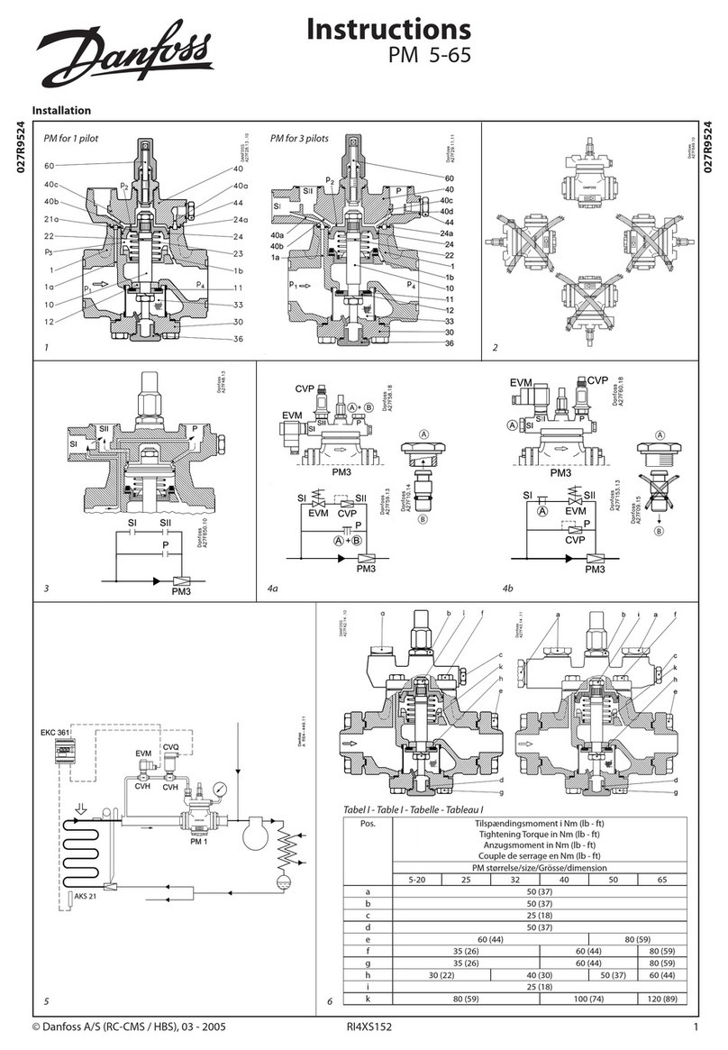
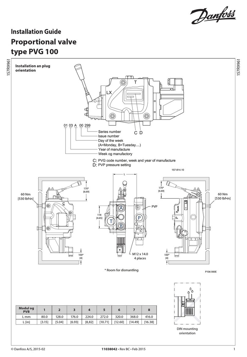
Installation Installation and plug orientation..............................................................................................................................................13
Connection, PVP, Pump Side Module.....................................................................................................................................13
Oil flow direction............................................................................................................................................................................14
Tightening Torques.......................................................................................................................................................................14
PVM, Lever Positions.....................................................................................................................................................................16
Setting of max. flow...................................................................................................................................................................... 16
Pressure Setting..............................................................................................................................................................................17
PVP, LS Relief Valve Pressure Setting.................................................................................................................................17
PVB, LS Relief Valve Pressure Setting.................................................................................................................................17
Option, Oil Flow Direction and Setting of max Flow.........................................................................................................18
Installation of PVE.......................................................................................................................................................................... 18
Bleeding.............................................................................................................................................................................................20
PVPE/PVH relief valves................................................................................................................................................................. 20
PVPH and LS connections...........................................................................................................................................................21
PVPE technical data.......................................................................................................................................................................21
Connection PVPE............................................................................................................................................................................22
PVP PVP, Pump Side Module.............................................................................................................................................................. 23
PVPD, PVPH, PVPE, Accessories for PVP................................................................................................................................. 25
PVLP / PVLA PVLP / PVLA, Shock and Suction Valve Port A/B.................................................................................................................27
PVBP, PVBR, PVBC, PVBU PVBP, PVBR, PVBC, PVBU Accessories for PVB......................................................................................................................29
PVM PVM, Mechanical Activating Module......................................................................................................................................31
PVMD and PVH PVMD, Cover for PVM and PVH, Hydraulic Activation...................................................................................................... 33
PVGI PVGI, Interface for PVG 120 and PVG 32................................................................................................................................ 34
PVEH and PVEO PVEH and PVEO, Electrical Activating Module, ON-OFF...................................................................................................35
PVT PVT, Tank Side Module – Upper Part.......................................................................................................................................37
PVT, Tank Side Module – Lower Part.......................................................................................................................................39
PVAS and PVGI PVGI, Assembly Kit.........................................................................................................................................................................41
PVAS, Assembly Kit........................................................................................................................................................................41
Asssembly sequence............................................................................................................................................................... 41
Set of seals Set of Seals .......................................................................................................................................................................................43
PVG 120 Modules Selection Chart
PVG 120 module selection chart.............................................................................................................................................. 44
Order specification
Service Manual PVG 120 Proportional Valve Group
Contents
520L0247 • Rev JA • May 2014 3
