manuals.online logo
Brands
  1. Home
  2. •
  3. Brands
  4. •
  5. Danfoss
  6. •
  7. Control Unit
  8. •
  9. Danfoss DHP-R 7UA HPC EM User manual

Danfoss DHP-R 7UA HPC EM User manual

Other Danfoss Control Unit manuals
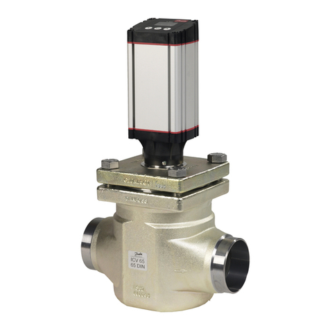
Danfoss ESMD User manual

Danfoss

Danfoss ESMD User manual

Danfoss VLT HVAC Drive FC 102 User manual

Danfoss

Danfoss VLT HVAC Drive FC 102 User manual

Danfoss VF3 DN 200 User manual

Danfoss

Danfoss VF3 DN 200 User manual

Danfoss TS 12.5 User manual

Danfoss

Danfoss TS 12.5 User manual

Danfoss HPVB15 User manual

Danfoss

Danfoss HPVB15 User manual

Danfoss KP 1 User manual

Danfoss

Danfoss KP 1 User manual

Danfoss HPV User manual

Danfoss

Danfoss HPV User manual

Danfoss EVUL 1 User manual

Danfoss

Danfoss EVUL 1 User manual

Danfoss PVG 32 Manual

Danfoss

Danfoss PVG 32 Manual

Danfoss PM 5-65 User manual

Danfoss

Danfoss PM 5-65 User manual

Danfoss 176F3417 User manual

Danfoss

Danfoss 176F3417 User manual

Danfoss VHX-DUO Installation instructions manual

Danfoss

Danfoss VHX-DUO Installation instructions manual

Danfoss EVR 2 User manual

Danfoss

Danfoss EVR 2 User manual

Danfoss ICF 15 User manual

Danfoss

Danfoss ICF 15 User manual

Danfoss PCV-VFG 21 User manual

Danfoss

Danfoss PCV-VFG 21 User manual

Danfoss SVA-S SS 15 User manual

Danfoss

Danfoss SVA-S SS 15 User manual

Danfoss ASV-PV User manual

Danfoss

Danfoss ASV-PV User manual

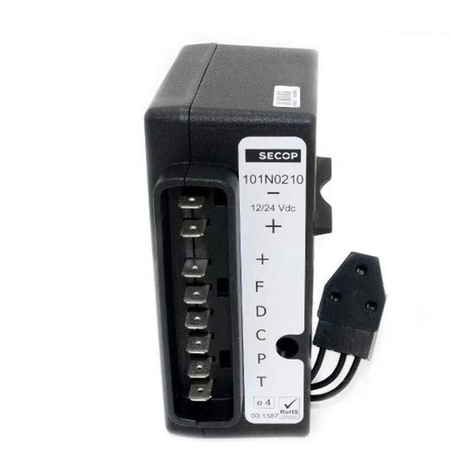
Danfoss 101N0210 User manual

Danfoss

Danfoss 101N0210 User manual

Danfoss GBC 6s User manual

Danfoss

Danfoss GBC 6s User manual

Danfoss REG-SA SS 15 User manual

Danfoss

Danfoss REG-SA SS 15 User manual

Danfoss GPS 40-150 User manual

Danfoss

Danfoss GPS 40-150 User manual
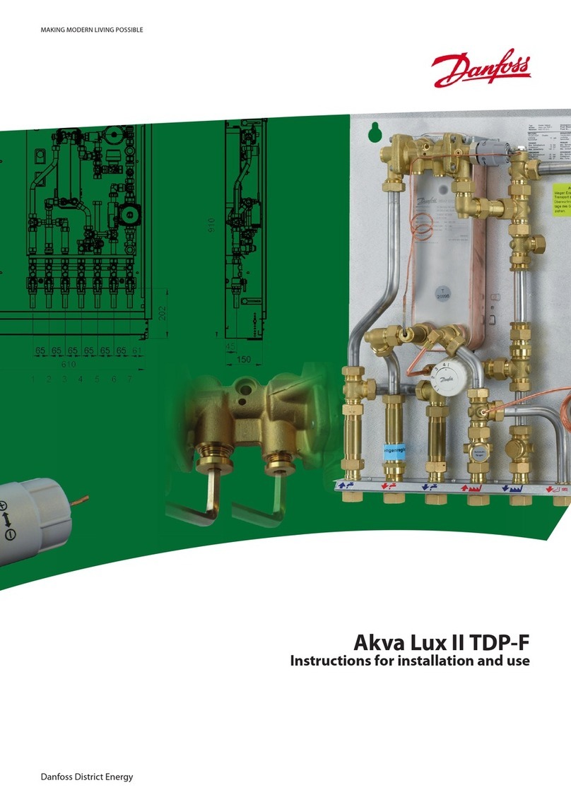
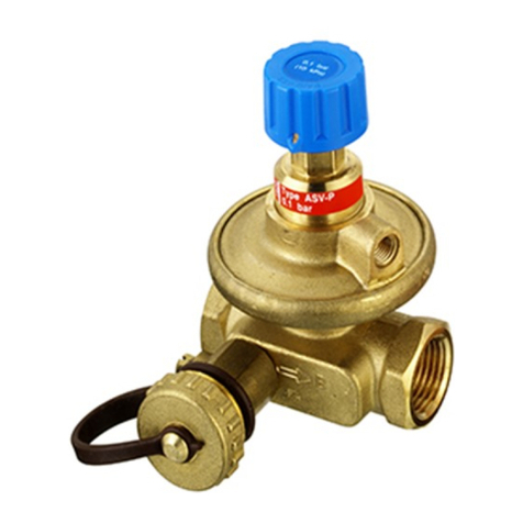
Danfoss ASV-I User manual

Danfoss

Danfoss ASV-I User manual
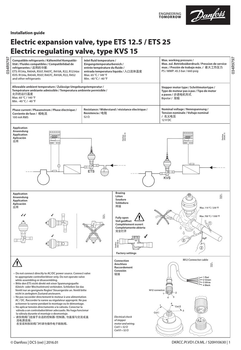
Danfoss EVR 2 User manual

Danfoss

Danfoss EVR 2 User manual

Danfoss AK-CM 102 User manual

Danfoss

Danfoss AK-CM 102 User manual

Popular Control Unit manuals by other brands

Seitz 14A80 user manual

Seitz

Seitz 14A80 user manual

Wilo RS485 Installation and operating instructions

Wilo

Wilo RS485 Installation and operating instructions

Becker CentralControl CC41 Commissioning Instruction

Becker

Becker CentralControl CC41 Commissioning Instruction

SICK CDB650 operating instructions

SICK

SICK CDB650 operating instructions

Panduit NetKey NKP5E88M Series installation instructions

Panduit

Panduit NetKey NKP5E88M Series installation instructions

MX Options Concentric Petite Fitting instructions

MX

MX Options Concentric Petite Fitting instructions

Clean Water Systems Fleck 2510 Installation & start?up guide

Clean Water Systems

Clean Water Systems Fleck 2510 Installation & start?up guide

Fairchild FSB44104A user guide

Fairchild

Fairchild FSB44104A user guide

LEGRAND Wattstopper LMIN-104 installation instructions

LEGRAND

LEGRAND Wattstopper LMIN-104 installation instructions

PMK ATT10BNCS instruction manual

PMK

PMK ATT10BNCS instruction manual

Tektronix TDS3FFT user manual

Tektronix

Tektronix TDS3FFT user manual

Woodward easYgen Technical manual

Woodward

Woodward easYgen Technical manual

Balluff BNI EIP-502-105-R015 user guide

Balluff

Balluff BNI EIP-502-105-R015 user guide

NXP Semiconductors TWR-LS1021A Getting started

NXP Semiconductors

NXP Semiconductors TWR-LS1021A Getting started

Advantech PCM-3117 Startup manual

Advantech

Advantech PCM-3117 Startup manual

Moons' Lin Engineering R701P user manual

Moons'

Moons' Lin Engineering R701P user manual

Aventics RV1 operating instructions

Aventics

Aventics RV1 operating instructions

MOTECK CB4M-S user guide

MOTECK

MOTECK CB4M-S user guide

manuals.online logo
manuals.online logoBrands
  • About & Mission
  • Contact us
  • Privacy Policy
  • Terms and Conditions

Copyright 2025 Manuals.Online. All Rights Reserved.

VMILF102
DHPR&DP
INSTALLATION INSTRUCTIONS
EXPANSION MODULE, HPC EM
COOLING MODULE, HPC CM
VMILF1022 – Danfoss
VMBQI102
VMBQI102
VMILF102 Danfoss – 3
Table of contents
Installation for WCS function (warm water loading) ... 4
Installation for TWC function (tap water control)...... 6
Installation for Shunt function ....................... 8
Important information!
24 VAC 1 must not be connected together with:
󰥎
 •24VAC2
 •24VDC
 •Otherequipmentthatuses0-10Vcontrolsignal
 •SignalgroundGND
24 VAC 2 must only be used as power supply to:
󰥎
 •Externalequipmentthatrequires0-10Vcontrolsignal
 •Auxiliarymodules
The two separate 24 VAC circuits must never be connected
󰥎 to each other or to protective ground.
The total power load on 24 VAC 1 respectively 24 VAC 2 must
󰥎 notexceed50VA.
VMILF1024 – Danfoss
VMBQI102
Expansion module, HPC EM
Theoperationaldescriptionfortheexpansionmoduleisavailableinthecontrollermanual.
Installation for WCS function (warm water loading)
Application
TheexpansionmoduleinWCSoperationalmodecontrolswarmwaterloadingofthe
water heaters.
WCS operation is achieved by setting the switch according to the figure.
Required accessories for installation
Submersiblesensor,Thermokon-DanelkoAKF1004140,itemno.086U3364
One of the following modular cables:
Modularcable0.3m,itemno.086U4227
Modularcable1.1m,itemno.086U4228
Modularcable10.0m,itemno.086U4229
Connectionblock,itemno.086U5121
Other accessories
PilotvalveVVL(2-way),heatexchanger(tapwatervvx),circulationpump.
System image
Heat exchanger
Aheatexchangerisconnectedbetweentheheatpumpandthecirculationforthewaterheatersasdepictedinthesystem
image above.
Circulation pump
Acirculationpumpisconnectedneartheheatexchanger.
Pilot valve
Apilotvalveisconnectedbetweenthecirculationpumpandtheheatexchanger.
Submersible sensor
Asubmersiblesensorisconnectedonthereturnlineoftheheatexchanger,asclosetotheheatexchangeraspossible.
Heat circuit
Hot gas circuit
Cooling agent circuit
VVB VVB VVB VVB
Heatexchanger
Modular cable
Steering valve
Circulation pump
Expansion module
WCS operation
Submersible sensor
return VVX
KV
VV
VVC
DHP-R Eco
VMBQI102
VMILF102 Danfoss–5
Connecting
󰥎 Note!Themaximumloadmaynotexceed50VA.
Expansion module
Theexpansionmoduleismountedintheelectriccabinetontheintendedrail.Ifthereisnoroom,themodulecanbeinstal-
ledinanexternal,enclosedcabinetandconnectedwithalongermodularcable.
• SettheswitchesonthefrontoftheexpansionmoduletotheWCSposition

• ConnectamodularcablebetweenHPCRMExp.outandHPCEMExp.in
Connections of expansion module for WCS operation:
Temperatureinput,T1:Submersiblesensor(heatexchangerreturnline)
Temperatureinput,T2:-
Analogueoutput0-10V,AO1:Signaltopilotvalve
Relay,DO1:Signaltocirculationpump(no-potentialclosure,maximum6A)
Exp.in:ConnectionfromHPCRM
Exp.out:Connectiontopossibleadditionalmodule.
Submersible sensor

• ConnecttoT1andGND
Circulation pump

• ConnecttoDO1.1to24VAC2.1

• ConnectDO1.2tothecontactorcoil(therelaycoil)andfurtherto24VAC2.2
Pilot valve

• ConnectAO1tothesignalinputofthepilotvalve

• ConnectGNDtopilotvalveGND.IfGNDismissinginthepilotvalve,connectGNDto24VAC2.2somewhereinthe
system. It is most appropriate to jumper terminals 144 and 146 in the controller cabinet.

• ConnectthepilotvalveterminalGto24VAC2.1

• ConnectthepilotvalveterminalG0to24VAC2.2.
•
Exp.in
GGNDG0Y1
Exp.out
DO1.1
T1
T2
AO1
GND
DO1.2
HPC EM
WCS
24 VAC 2.1
24 VAC 2.1
24 VAC 2.2
24 VAC 2.2
M
alt. GG
0Y1
24 VAC 2.1
24 VAC 2.2
AO1
0-10V
Circ. pump
FromExp.out
Submersible sensor
Pilot valve
VMILF1026 – Danfoss
VMBQI102
Installation for TWC function (tap water control)
Application
In the TWC mode, the expansion module ensures that outgoing hot tap wa- ter
and heat water circulation have a sufficiently high temperature, to prevent the pre-
sence of Legionella bacteria.
TWC operation is achieved by setting the switch according to the figure.
Required accessories
2 PT1000 strap-on temperature detectors with 2 m of cable, item no.
086U3365(itemnumbercorrespondsto1transmitter)
One of the following modular cables:
Modularcable0.3m,itemno.086U4227
Modularcable1.1m,itemno.086U4228
Modularcable10.0m,itemno.086U4229
Connectionblock,itemno.086U5121
System image
Sensor, water heater
Astrap-ontemperaturedetectorisconnectedonthesupplylineleadoftheendheater,beforethemixingvalve.
Sensor, hot water return
Astrap-ontemperaturedetectoris connectedonthereturnleadofthewarmwatercirculation,beforethecirculation
pump.
Heat circuit
Hot gas circuit
Cooling agent circuit
VVB VVB VVB VVB
Modular cable
Sensor, water heater
Electriccartridge
Sensor, hot water return
Expansion module
TWC function
KV
VV
VVC
DHP-R Eco
VMBQI102
VMILF102 Danfoss–7
Connecting
󰥎 Note!Themaximumloadmaynotexceed50VA.
Expansion module
Theexpansionmoduleismountedintheelectriccabinetontheintendedrail.Ifthereisnoroom,themodulecanbeinstal-
ledinanexternal,enclosedcabinetandconnectedwithalongermodularcable.
• SettheswitchesonthefrontoftheexpansionmoduletotheTWCposition

• ConnectamodularcablebetweenHPCRMExp.outandHPCEMExp.in
Connections of expansion module for TWC operation:
Temperature input, T1: Sensor, water heater
Temperature input, T2: Transmitter, hot water return
Analogueoutput0-10V,AO1:-
Relay,DO1:Signaltoelectriccartridge,hotwater(no-potentialclosure,maximum6A)
Exp.in:ConnectionfromHPCRM
Exp.out:Connectiontopossibleadditionalmodule.
Electric cartridge

• ConnecttoDO1.1to24VAC2.1.

• ConnectDO1.2tothecontactorcoil(therelaycoil)andfurtherto24VAC2.2.
Sensor, water heater

• ConnectthesensorcabletoT1andGND.
Sensor, hot water return

• ConnectthesensorcabletoT2andGND.
Exp.in
Exp.out
DO1.1
T1
T2
AO1
GND
DO1.2
HPC EM
TWC
24 VAC 2.1 24 VAC 2.2
Start signal for
electric cartridge
water heater
Hot water return
FromExp.out
VMILF1028 – Danfoss
VMBQI102
Installation for Shunt operation
Application
Intheshuntmode,theexpansionmodulemaintainstherequiredtemperaturefora
second heat circuit.
The shunt function is achieved by setting the switch according to the figure.
Required accessories
1PT1000strap-ontemperaturedetector,itemno.086U3365
One of the following modular cables:
Modularcable0.3m,itemno.086U4227
Modularcable1.1m,itemno.086U4228
Modularcable10.0m,itemno.086U4229
Connectionblock,itemno.086U5121
Other accessories
Shunt valve, circulation pump.
System image
Sensor, shunt temperature
Astrap-ontemperaturedetectorisconnectedonthesupplylineoftheheatcircuit,afterthecirculationpump.
Heat circuit 1
Heat circuit 2
Hot gas circuit
Cooling agent circuit
VVB VVB VVB VVB
Shunt valve
Sensor, shunt temperature
Circulation pump
Modular cable
Expansion module
Shunt function
KV
VV
VVC
DHP-R Eco
VMBQI102
VMILF102 Danfoss–9
Connecting
󰥎 Note!Themaximumloadmaynotexceed50VA.
Expansion module
Theexpansionmoduleismountedintheelectriccabinetontheintendedrail.Ifthereisnoroom,themodulecanbeinstal-
ledinanexternal,enclosedcabinetandconnectedwithalongermodularcable.
• SettheswitchesonthefrontoftheexpansionmoduletotheShuntposition.

• ConnectamodularcablebetweenHPCRMExp.outandHPCEMExp.in
Connections of expansion module for shunt operation:
Temperature input, T1: Sensor, shunt temperature.
Temperatureinput,T2:-
Analogueoutput0-10V,AO1:Signaltoshuntvalve.
Relay,DO1:Signaltocirculationpump(no-potentialclosure,maximum6A).
Exp.in:ConnectionfromHPCRM.
Exp.out:Connectiontopossibleadditionalmodule.
Sensor, shunt temperature

• ConnecttoT1andGND
Circulation pump

• ConnecttoDO1.1to24VAC2.1.

• ConnectDO1.2tothecontactorcoil(therelaycoil)andfurtherto24VAC2.2.
Shunt valve

• ConnectAO1tothesignalinputofthepilotvalve.

• ConnectGNDtopilotvalveGND.IfGNDismissinginthepilotvalve,connectGNDto24VAC2.2somewhereinthe
system. It is most appropriate to jumper terminals 144 and 146 in the controller cabinet.

• ConnectthepilotvalveterminalGto24VAC2.1.

• ConnectthepilotvalveterminalG0to24VAC2.2.
Exp.in
GGNDG0Y1
Exp.out
DO1.1
T1
T2
AO1
GND
DO1.2
HPC EM
Shunt
24 VAC 2.1
24 VAC 2.1
24 VAC 2.2
24 VAC 2.2
0-10V
alt.
M
GG
0Y1
24 VAC 2.1
24 VAC 2.2
AO1
Circ. pump
FromExp.out
Shunt temperature
Shunt valve
VMILF10210 – Danfoss
VMBQI102
Inputs and outputs, HPC EM
Temperature inputs
Input Shunt TWC WCS
T1 Shunt temperature HW heater temp WCS temperature
T2 – HW return temp –
Analogue outputs
Outputs Shunt TWC WCS
AO1 Control signal – Control signal
Relay outputs
Outputs Shunt TWC WCS
DO1 Circulation pump Heater HW Circulation pump