Danfoss MPCAN User manual

Revision history Table of revisions
Date Changed Rev
March 2022 Updated safety instructions and technical descriptions 0201
January 2019 Rebranded to Danfoss Power Solutions 0101
User Manual
MPCAN Receiver
2 | ©Danfoss | March 2022 BC292573933619en-000201

Safety instructions FCC rules..............................................................................................................................................................................................4
General safety....................................................................................................................................................................................4
Safety warnings.................................................................................................................................................................................5
Technical description Dimensions.........................................................................................................................................................................................6
Hardware description..................................................................................................................................................................... 7
MPCAN detailed description........................................................................................................................................................7
Installation Receiver installation........................................................................................................................................................................ 9
Input and output configuration............................................................................................................................................... 10
STOP category 3 PLe................................................................................................................................................................10
Pinout............................................................................................................................................................................................11
Troubleshooting MPCAN Receiver Faceplates...................................................................................................................................................... 12
MPCAN400-900MHz LED troubleshooting...........................................................................................................................12
2.4GHz Receiver LED troubleshooting................................................................................................................................... 13
User Manual
MPCAN Receiver
Contents
©Danfoss | March 2022 BC292573933619en-000201 | 3

FCC rules
This equipment has been tested and found to comply with the limits for a Class A digital device, pursuant
to Part 15 of the FCC Rules.
Changes or modifications not expressly approved by the manufacturer can void the user's authority to
operate the equipment.
To comply with FCC RF exposure compliance requirements, this device and its antenna must not be
collocated with, or operating in conjunction with, any other antenna or transmitter, may not cause
harmful interference, and must accept any interference received, including interference that may cause
undesired operation.
The limits are designed to provide reasonable protection against harmful interference when the
equipment is operated in a commercial environment. This equipment generates, uses, and can radiate
radio frequency energy, and if not installed and used in accordance with the instruction manual, may
cause harmful interference to radio communications.
Operation of this equipment in a residential area is likely to cause harmful interference in which case the
user will be required to correct the interference at his own expense.
W
Warning
Le présent appareil est conforme aux CNR d'Industrie Canada applicables aux appareils radio exempts de
licence. L'exploitation est autorisée aux deux conditions suivantes:
1. l'appareil ne doit pas produire de brouillage, et
2. l'utilisateur de l'appareil doit accepter tout brouillage radioélectrique subi, même si le brouillage est
susceptible d'en compromettre le fonctionnement.
MPCAN General Safety
The following safety instructions must be read carefully to install and use the product properly, and to
keep it in perfect working condition, and to reduce the risk of misuse.
•Strictly adhere to the installation instructions contained in this document.
•Make sure that professional and competent personnel carry out the installation.
•Ensure that all site and prevailing safety regulations are fully respected.
•Make sure that this document is permanently available to the operator and maintenance personnel.
•Keep the transmitter out of reach of non-authorized personnel.
•Remove the transmission key when the set is not in use.
•Check each working day the STOP button and other safety measures. When in doubt, press the STOP
button.
•Whenever several sets have been installed, make sure the transmitter is the right one. Identify the
machine controlled on the label for this purpose on the transmitter or by using the display (in case it
has one).
•Service the equipment periodically.
•When carrying out repairs, use spare parts supplied by Danfoss only.
W
Warning
Potential damage to the operator or the product. Do not use this product on machines in potentially
explosive atmospheres unless the model is ATEX/RATEX certified to work in such conditions.
User Manual
MPCAN Receiver
Safety instructions
4 | ©Danfoss | March 2022 BC292573933619en-000201
MPCAN Safety Warnings
Potential damage to operator and product.
Follow the guidelines below to reduce risk of injury to the operator and the product.
•Use the device with the manufacturer's battery and battery charger (if applicable).
•Only allow qualified personnel to operate the equipment.
•Always set the STOP button in the off position when not in use.
•Always press STOP before plugging in tether cable (if applicable).
•Remove the Tether connection on the transmitter First (if applicable).
•Do not operate product when visibility is limited.
•Make sure product is compatible with the machine.
•Avoid knocking or dropping the product.
•Do not use the product if a failure is detected.
Changes or modifications not approved by Danfoss can void the user's authority to operate this product.
Quick reference precautions
User Manual
MPCAN Receiver
Safety instructions
©Danfoss | March 2022 BC292573933619en-000201 | 5
MPCAN dimensions
Dimensions in mm
15.75
35.99
29.20
133.03
R 3.70
42.27
118.73
101.60
324.52
92.25
User Manual
MPCAN Receiver
Technical description
6 | ©Danfoss | March 2022 BC292573933619en-000201
MPCAN hardware description
3
4
5
7
8
9
10
6
1
2
1. Fixing slots (fixed assembly or anti-vibration)
2. External antenna
3. Removable internal EEPROM
4. External LEDs
5. RF Module
6. CAN bus termination
7. DEUTSCH connector pinout
8. Tether connection
9. STOP relays
10. Internal fuse, 7.5A
MPCAN detailed description
Technical data
Specification Value
Stop function (400 - 900 MHz) Cat. 3-PLd
Stop Function (2.4 GHz) Cat. 4-PLe
Ingress protection IP65/NEMA4
Frequency band - ERP 433.050 to 434.040 MHz; ERP<1 mW
434.040 to 434.790 MHz; ERP<10mW
869.700 to 870.000 MHz; ERP<5 mW
902.000 to 928.000 MHz; ERP<1mW
2405MHz to 2475MHz 20dBm/100mW
User Manual
MPCAN Receiver
Technical description
©Danfoss | March 2022 BC292573933619en-000201 | 7
Technical data (continued)
Specification Value
Range Line of sight (guaranteed) 100m
AC power supply N/A
DC power supply 8 - 35 Vdc
Receiver Current Consumption 200mA
Antenna External/Internal
Removable EEPROM Internal
Signaling External
STOP Outputs (400 - 900MHz) 2
STOP Outputs (2.4GHz) 2
Start Output N/A
Safety Relay Output N/A
ON/OFF outputs 4 (2A per output)
Proportional outputs N/A
CAN Bus Protocols (400-900MHz) CANopen
CAN Bus Protocols (2.4GHz) CANopen, J1939
ON/OFF inputs 4
Proportional inputs N/A
Reponse time 100ms
Maximum Total output current 7.5A
Operating temperature range -20° C to +70° C (-4° F to +158° F)
Storage Temperature Range (24h) -25ºC to 75ºC (-13ºF to 167ºF)
Storage Temperature Range (long periods) -25ºC to 55ºC (-13ºF to 131ºF)
Relative Humidity max. 95% without condensation
Weight 300 grams
Dimensions 117 x 133 x 36
Tether connection Yes (M12 Connector)
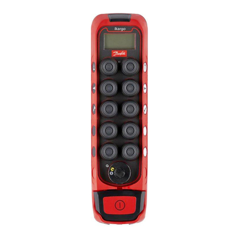
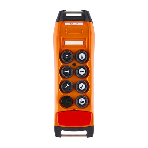
Associated transmitters (400 - 900MHz) Ikargo1, Ikargo2, T70 1, T70 2, T70 1 HALL, T70 2 HALL, T70 1 ATEX, T70 2
ATEX, IK2, IK3, IK4
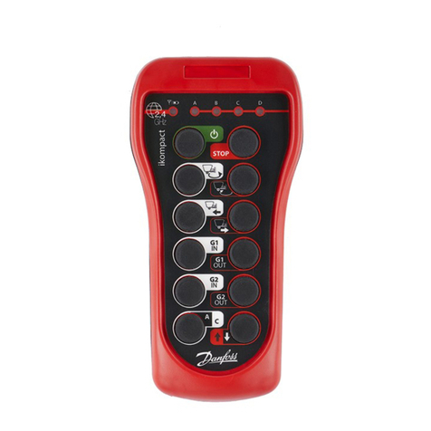
Associated transmitters (2.4 GHz) Ikompact, Ikore, IkoreB, IK2, IK3, IK4
User Manual
MPCAN Receiver
Technical description
8 | ©Danfoss | March 2022 BC292573933619en-000201
MPCAN receiver installation
The below information describes hazards to be aware of during installation and steps to locate the
receiver.
Risk of shock
Completely shut down the machine when installing the receiver.
Check the power supply and shut off the main switch to disconnect the interface cable between the
receiver and the machine's electrical box.
1. Find an easily accessible and clear location with a direct vision between the receiver's antenna and
the transmitter's working area.
7 8 9 10 11
CANL
12
GND
6 5
K4/ IN4
4 3 2
CANH
1
Vin
KSTOP 2.2KSTOP 1.2
K3/ IN3
K1/ IN1 K2/ IN2 KSTOP 1.1 KSTOP 2.1
2. Optional: If it is difficult to achieve direct vision between the receiver's antenna and the transmitter's
working area, it is recommended to use an extended antenna in a clear location (only for models that
allow an antenna).
In areas of high vibration, the use of dampers is advised.
7 8 9 10 11
CANL
12
GND
6 5
K4/ IN4
4 3 2
CANH
1
Vin
KSTOP 2.2KSTOP 1.2
K3/ IN3
K1/ IN1 K2/ IN2 KSTOP 1.1 KSTOP 2.1
3. Proceed to connect the power supply. Use the connection block diagram provided with the system,
where the correspondence between the transmitter maneuvers and the receiver's outputs are
detailed.
7 8 9 10 11
CANL
12
GND
6 5
K4/ IN4
4 3 2
CANH
1
Vin
KSTOP 2.2KSTOP 1.2
K3/ IN3
K1/ IN1 K2/ IN2 KSTOP 1.1 KSTOP 2.1
4. Check if the electrical installation and verify if there's an option to connect the neutral or the ground
cable. In that case, don't forget to connect the ground cable.
The use of fireproof or flame retardant cables are recommended for the connection.
User Manual
MPCAN Receiver
Installation
©Danfoss | March 2022 BC292573933619en-000201 | 9

MPCAN input and output configuration
This receiver has four digital outputs or four digital inputs. The hardware is shared by these inputs and
outputs and they are chosen by EEPROM configuration.
Each input and output cannot be configured together at the same time.
The MPCAN includes a 7.5A internal fuse.
A1
A7
A8
A6
A5
IN1
IN2
IN3
IN4
Internal Vcc
MPCAN STOP category 3 PLe
Stop function is performed by two relays in series or parallel.
A10 and A9 pins should not be connected directly to GND.
Serie
ext
conne
external
connection
STOP
+IN
STOP
+OUT
A12 GND
A1 Vin
A10
A3
A9
A4
STOP2
CM
NO
STOP1
CM
NO
User Manual
MPCAN Receiver
Installation
10 | ©Danfoss | March 2022 BC292573933619en-000201
Parallel
external
connection
A
A12
GND
A1
Vin
1
STOP1
+OUT
STOP2
+IN
STOP2
+OUT
STOP1
+IN
A10
A3
A9
A4
CM
NO
STOP2
STOP1
NO
CM
MPCAN pinout
7 8 9 10 11 12
6 5 4 3 2 1
Pin Description
1 Vin
2 CANH
3 KSTOP 2.2
4 KSTOP 1.2
5 K4/IN4
6 K3/IN3
7 K1/IN1
8 K2/IN2
9 KSTOP 1.1
10 KSTOP 2.1
11 CANL
12 GND
User Manual
MPCAN Receiver
Installation
©Danfoss | March 2022 BC292573933619en-000201 | 11

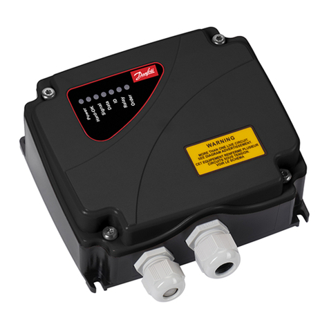
MPCAN Receiver Faceplates
400-900 MHz and 2.4GHz Faceplates
MPCAN400-900MHz LED troubleshooting
LED Characteristic Description Action
POWER Green; pulsing Receiver is starting up Wait until start-up process is
finished
HARDOK Green; continuous Receiver hardware OK Operate
Red; pulsing EEPROM error; data corruption; CAN bus error (if CANERR
activates) Reprogram EEPROM
Red; other Electronic board hardware breakdown Replace electronic board
SIGNAL LED off No radio signal detected -
LED on + transmitter switched
off Radio channel occupied Change transmitter's frequency
channel
LED on + DATA switched off Radio channel occupied by non Danfoss system Change transmitter's frequency
channel
DATA Green; pulsing Receiving good frames OK
ID LED off + DATA LED on No valid ID; Danfoss system nearby If channel not occupied, check
chosen ID in the transmitter or
reset the receiver
LED on + SIGNAL LED on +
DATA LED on Valid frames received from the transmitter; correct link OK
RELAY Green STOP relay activated -
ORDER Green - -
CAN_RUN Green; switched on Operational state OK
Green; pulsing Activating operational state -
CAN_ERR Red; switched on CAN bus error Check CAN connection
Red; pulsing No bus connection Check bus termination
resistance
LED off Correct communication OK
User Manual
MPCAN Receiver
Troubleshooting
12 | ©Danfoss | March 2022 BC292573933619en-000201
2.4GHz Receiver LED troubleshooting
The troubleshooting LEDs are located on the receiver board or accessible on the outside. Use the
following table to identify faults and corrective action.
In order to reach the internal signaling, the receiver must be accessible, connected and the screws
located on the receiver lid must be unscrewed using the proper screw driver whenever the LEDs are not
externally visible.
The LEDs on the receiver board are POWER, STATUS, DIAG1, DIAG2, ORDER, RELAY, CANERR and CANRUN
in that order.
Please do check the following website for further information:
https://troubleshooting.dps-rct.com/en/customer-service-center
LED Color and frequency Pulse frequency Description Action
POWER Green | continuous Switched ON if powered Check power supply if LED is
switched off.
STATUS Blue | fast pulses System is starting; establishing connection with
radio and EEPROM Wait
Blue | continuous Waiting for transmitter communication, coming
from ACTIVE STOP Release STOP button and press
START on the transmitter.
Blue | slow pulses Waiting for transmitter communication, coming
from PASSIVE STOP Press Start on the Transmitter
Green | continuous Working Operate
Red | slow pulses EEPROM module missing or corrupt Check EEPROM and reprogram
if necessary
Red | double pulses Radio communication error Replace receiver
Red | triple pulses Secondary micro error or error between micro
communication Replace receiver
Red | 4 pulses ERROR Check DIAG1 LED
Red | 5 pulses After 15 sec Not all expansion boards have been
initialized Check CAN wiring and
Configuration(EEP or Expansion
ID#), Check Bus Termination.
Red | 1 Long + 1 short
pulse CAN Signature ERROR Check Signature in Compliance
Block and EEPROM are the
same.
User Manual
MPCAN Receiver
Troubleshooting
©Danfoss | March 2022 BC292573933619en-000201 | 13
LED Color and frequency Pulse frequency Description Action
DIAG1 Orange | slow pulses Low tension in the receivers power supply Supply the system with the
correct voltage
Orange | double pulses Hardware error Replace receiver
Orange | triple pulses
Orange | 4 pulses
Green | slow pulses Low link quality N/A
Green | double pulses Medium link quality N/A
Green | triple pulses High link quality N/A
DIAG2 NOT USED NOT USED NOT USED N/A
ORDER Green | continuous LED ON Whenever any output is ON N/A
RELAY Green | continuous STOP relay activated N/A
CANERR Red | slow pulses CAN Error, physical Layer Verify Connections
Red | double pulses One expansion has Stopped working Verify Expansion boards
Red | 4 pulses A Transmitted CAN frame has been lost N/A
Red | 5 pulses A Received CAN Frame has been lost N/A
Red | continuous CAN Bus OFF Verify CAN connections and
Status.
CANRUN Green | fast pulses Pre operational Status, Receiver waiting for the
controller. Controller must send the
Operational code to the
Receiver.
Green | continuous Receiver connected to the CAN network and
operational N/A
User Manual
MPCAN Receiver
Troubleshooting
14 | ©Danfoss | March 2022 BC292573933619en-000201
Danfoss Power Solutions is a global manufacturer and supplier of high-quality hydraulic and
electric components. We specialize in providing state-of-the-art technology and solutions
that excel in the harsh operating conditions of the mobile off-highway market as well as the
marine sector. Building on our extensive applications expertise, we work closely with you to
ensure exceptional performance for a broad range of applications. We help you and other
customers around the world speed up system development, reduce costs and bring vehicles
and vessels to market faster.
Danfoss Power Solutions – your strongest partner in mobile hydraulics and mobile
electrification.
Go to www.danfoss.com for further product information.
We offer you expert worldwide support for ensuring the best possible solutions for
outstanding performance. And with an extensive network of Global Service Partners, we also
provide you with comprehensive global service for all of our components.
Local address:
Danfoss
Power Solutions GmbH & Co. OHG
Krokamp 35
D-24539 Neumünster, Germany
Phone: +49 4321 871 0
Danfoss
Power Solutions ApS
Nordborgvej 81
DK-6430 Nordborg, Denmark
Phone: +45 7488 2222
Danfoss
Power Solutions (US) Company
2800 East 13th Street
Ames, IA 50010, USA
Phone: +1 515 239 6000
Danfoss
Power Solutions Trading
(Shanghai) Co., Ltd.
Building #22, No. 1000 Jin Hai Rd
Jin Qiao, Pudong New District
Shanghai, China 201206
Phone: +86 21 2080 6201
Danfoss can accept no responsibility for possible errors in catalogues, brochures and other printed material. Danfoss reserves the right to alter its products without notice. This also applies to products
already on order provided that such alterations can be made without subsequent changes being necessary in specifications already agreed.
All trademarks in this material are property of the respective companies. Danfoss and the Danfoss logotype are trademarks of Danfoss A/S. All rights reserved.
©Danfoss | March 2022 BC292573933619en-000201
Products we offer:
•Cartridge valves
•DCV directional control
valves
•Electric converters
•Electric machines
•Electric motors
•Gear motors
•Gear pumps
•Hydraulic integrated
circuits (HICs)
•Hydrostatic motors
•Hydrostatic pumps
•Orbital motors
•PLUS+1®controllers
•PLUS+1®displays
•PLUS+1®joysticks and
pedals
•PLUS+1®operator
interfaces
•PLUS+1®sensors
•PLUS+1®software
•PLUS+1®software services,
support and training
•Position controls and
sensors
•PVG proportional valves
•Steering components and
systems
•Telematics
Hydro-Gear
www.hydro-gear.com
Daikin-Sauer-Danfoss
www.daikin-sauer-danfoss.com
Table of contents
Other Danfoss Remote Control manuals

Danfoss
Danfoss Ikargo2 User manual

Danfoss
Danfoss Ikompact User manual

Danfoss
Danfoss Ikompact User manual

Danfoss
Danfoss R13 F User manual

Danfoss
Danfoss T70 1 HALL User manual

Danfoss
Danfoss 103E7 Assembly Instructions

Danfoss
Danfoss 175G9004 User manual

Danfoss
Danfoss MP08A User manual

Danfoss
Danfoss IKP1000 User manual

Danfoss
Danfoss CF-RC User manual

Danfoss
Danfoss TM70 User manual

Danfoss
Danfoss SET3M User manual

Danfoss
Danfoss R06 User manual

Danfoss
Danfoss CF-RC User manual

Danfoss
Danfoss 102E7 User manual

Danfoss
Danfoss CF-RC User manual

Danfoss
Danfoss WS103 User manual

Danfoss
Danfoss FP975 Assembly Instructions

Danfoss
Danfoss IKORE B User manual

Danfoss
Danfoss IK2 User manual