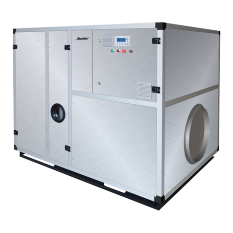
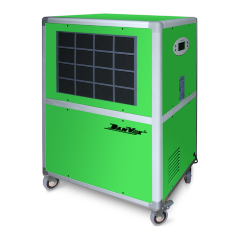
DanVex DEH-3K User manual

DanVex DEH-3K
DanVex DEH-5K
DanVex DEH-10K
Industrial Condensing Dehumidifiers
■ Any questions,please contact the manufacturer or dealer in time.
■ Therepairandmaintenance mustbeconductedby certi fedprofessionals.
■ Please read the manual carefully and in full before using the unit.
Manual of dehumidifier
DEH-3K
DEH-5K
DEH-10K

·Purpose of the Manual
Through the manual, you can understand the structure, installation specifications, control principles, process flow and
operation methods of the cabinet-type dehumidifier.
· Knowledge Required
You need to have knowledge of automatic control and air handling to understand the manual.
·Contents Included
The manual explains in detail the functions, operation, daily maintenance and troubleshooting of the cabinet-type dehumidifier.
·All rights reserved
Copying of this manual, or part of it, is forbidden without prior written permission from DANVEX.The warranty and technical
support of this product are only valid in the country or region of purchase.
Foreword
UL/484-2014 American standard for Room air conditioners
ANSI/UL94 American standard for Safety of Flammability of Plastic Materials for Par ts in Devices and Appliances
UL/969 American standard for marking and labeling systems used for permanent product identification
UL/474-1993 American Safety Standard for Dehumidifiers
GB/T191-2008 China National Standard for Packaging - Pictorial Markings for Handling of Goods
ANSI/AHAM DH-1-2008 ANSI/AHAM Standard for dehumidifiers
This unit must be operated by trained professionals, otherwise it will cause casualties or property damage.
Please read and understand this manual thoroughly before operation to avoid damage to the unit or personal injury or death caused by
misoperation.
Please contact the supplier or the manufacturer if there are any issues arises that are not stated in this manual.
Standards and Codes:
GB/4706.32-2004 China National Standard No. GB/4706.32-2004, Code of household and similar electrical appliances Particular
requirements for heat Pumps, air-conditioner and dehumidifier
IEC 60335-2-40 International safety Standard for electric heat pumps, including sanitary hot water heat pumps, air-conditioners, and
dehumidifiers incorporating sealed motor- compressors
Please keep this manual for later reference.
GB/T16803-2018 China National Standard No. GB/T16803-2018, Code of of heating, ventilating, air conditioning and air cleaning
terminology
GB/T2518 China National Standard No.GB/T2518, Code of of continuously hot-dip zinc and zinc alloy coated steel sheet
GBJ16-87 China National Standard No.GBJ16-87, Code for fire protection of building design
GB/T19411-2003 China National Standard for dehumidifiers
GB/T17791-2007 China National Standard No. GB/T17791-2007, Code of of Specification for seamless copper tube for air conditioning
and refrigeration field service
GB/755-2000 China National Standard No. GB/755-2000, Code of of Rotating electrical machines--Rating and performance
GB/50016-2006 China National Standard No.GB/50016-2006, Code of Design on Building Fire Protection and Prevention
GB/50243-2002 China National Standard No. GB/50243-2002,Code of acceptance for construction quality of ventilation and air
conditioning works
GB/50019-2003 China National Standard No. GB/50019-2003,Code for Design of Heating Ventilation and Air Conditioning
GB/50015-2019 China National Standard No. GB/50015-2019,Code for design of building water supply and drainage
GB/T7725-2004 China National Standard No. GB/T7725-2004, Code for room air conditioners
GB/T18883-2002 China National Standard for indoor Air Quality Standard
NOTE
Warning
This symbol indicates the rules that must be followed! If it is not strictly followed,
it may cause mild to moderate damage to the machine or signs of personal injury.
This symbol indicates actions that must be prohibited!! If not strictly followed,
it may cause serious damage to the machine or personal injury or death.
When a problem occurs (such as a
burning smell, etc.), please turn
off the unit and unplug the power
cord. (Cut off the power supply).
Please follow this manual for
installation. Please read this manual
carefully before running or servicing
the unit.
The space above the equipment
installation is at least 50 cm, the
rear and the left and right sides
are at least 100 cm, and the front
is at least 200 cm.
Before installation, please check
whether the power cord used is
consistent with the power required
on the nameplate, and check the
safety of the power supply.
Be sure to use special accessories
and parts during installation.
Other wise, it may cause water
leakage, electric shock, fire and
other accidents.
The power connection of this unit
adopts Y-type connection, and the
diameter of the power cord should
be large enough. If the power cord
is damaged, in order to avoid danger,
the power cord should be replaced
by the manufacturer or professionals.
Do not inser t your fingers or objects
into the air outlet or return air grille.
Do not start or stop the unit by
pulling out the plug.
Do not allow children to operate
the unit.
The unit can only be cleaned after
shutting down and cutting off the
power supply, otherwise you may
get an electric shock or be injured.
The installation should be carried
out by the seller or qualified
professionals, please do not install
the unit by yourself. Incorrect
installation may cause accidents
such as water leakage, electric
shock or fire.
The unit should be grounded, and
the power socket must be equipped
with a ground wire to ensure that
the machine is effectively grounded
through the power socket to avoid
the risk of electric shock. Do not
connect the ground wire to gas
pipes, water pipes, lightning rods or
telephone wiring.
Drainage pipes should be installed
correctly in accordance with the
installation instructions to ensure
proper drainage, and insulation
measures should be taken to avoid
condensation.Improper installation
of pipes will cause water leakage.
Volatile liquids such as thinner or
gasoline will damage the
appearance of the unit. (Only use a
soft dr y cloth and a damp cloth
dampened with a neutral detergent
to clean the casing of the unit).
Once the unit is turned on, it must
run for at least 5 minutes before it
can be turned off, otherwise it will
affect the compressor oil return.
Do not operate the unit with
wet hands.
Do not pour or rinse the unit with
water, otherwise it may cause
malfunction or risk of electric shock.
When the unit is not used for a
long time, please cut off the power
supply of the unit.
Af ter the unit is installed, electric
leakage test should be carried out.
Do not repair the unit by yourself.
Wrong maintenance will cause
electric shock or fire.
Do not step on the unit, and do
not place objects on or on the air
inlet and outlet of the unit.
Af ter installation, please check
and confirm whether the
connections of drain pipes, ducts
and wires are correct to prevent
water leakage, refrigerant leakage,
electric shock or fire accidents.
Do not use or store flammable
and explosive dangerous goods
next to the unit. There should
be at least 1.5m between the
combustible surface and the unit.
For units using line control,
the line controller store must
be connected first, otherwise
the line controller will be unusable.
DANVEX assumes no responsibility for personal injury or equipment damage caused by improper installation, commissioning,
unnecessary maintenance, and failure to follow the regulations and instructions in this manual.
SPECIAL
ACCESSORIES
SPECIAL
TABLE OF CONTENTS
1. General
1.1 Application
1.2 Content
2. Unit
2.1 Introduction
2.2 Working Principle
2.3 Performance Curve
2.4 Airflow Direction
(2.5.1)Unit Housing
(2.5.2)Air Inlet & Outlet
(2.5.3)Dehumidification Section
(2.5.4)Compressor
2.5 Housing & Structure
(2.5.5)Throttling Section
(2.5.6)Controller Protection
(2.5.7)Structure & Dimension
2.6 Technical Parameters
3. Installation
3.1 Introduction
3.2 Delivery & Storage
3.3 Inspection
3.4 Unit Movement
3.5 Location Requirement
(3.8.1)Drainage Pipe Test
3.6 Ground Level
3.7 Duct Connection
3.8 Negative-pressure Drainage Pipe Installation
3.9 Wiring
3.10 External Humidity Sensor Connection
4. Ducting
4.1 Introduction
(4.1.1)Non-ducted Installation
(4.1.2)Ducting for Fresh Air
(4.1.3)Installation with HVAC system
5. Commitioning
5.1 Introduction
5.2 Unit Check
(5.2.1)Duct Check
(5.2.2)Wiring Check
(5.2.3)Controller Check
6. Controller
6.1 General
(6.1.1)Controller Terminals
(6. 1 . 2 )Terminals Diagram
(6.1.3)Controller’s Interface
(6. 1 . 4) Parameters Setting
(6.1.5)Icon
6.2 Controller Logic
(6.2.1)Working Mode
(6.2.2)Dehumidification Working Mode
6.3 Initial Value
6.4 Fan Control
6.5 Air Damper Control
6.6 Defrost Control
6.7 Alarm
(6.7.1)Filter Alarm
(6.7.2)Built-in temp.&humid sensor Error
(6. 7 . 3) RS485-1 Communication Error
6.8 Working Status Display
6.9 Error Code
6.10 External temp.&humid sensor
6.11 Parameters Set
6.12 RS4885-2 Mod-bus Communication Protocol
6.13 Wi-Fi Connection
7. Maintenance
7.1 Introduction
7.2 Filter
7.3 Motor
7.4 Technical Description
8. Troubleshooting
8.1 Introduction
8.2 Description
9. Electric Diagram
1
1
1
2
2
2
3
4
4
4
4
5
5
5
5
6
8
9
9
9
9
9
9
9
10
10
11
12
12
13
13
13
13
14
15
15
15
15
16
17
17
18
19
20
21
21
21
21
22
22
23
23
23
23
24
24
25
26
27
29
29
30
30
31
15
5.3 Unit Running
5.4 Air rate Adjustment
5.5 Performance Test
16
16
16
17
17
23
24
29
29
29
30

Cabinet-type dehumidification equipment adopts direct evaporative cooling design, which can dry the air
under atmospheric pressure. The dehumidification equipment can dehumidify the air with a temperature range of
5°C to +35°C within 100% relative humidity.It is widely used in hotels, office buildings, hospitals, commercial and
residential, scientific research institutions and other places.
The cabinet-type dehumidifier can work normally in the following temperature range.It will not work normally
outside this range, which is not a quality problem of the equipment itself.
1.1 Application
Product dr ying
§
Business hotels.
§
This manual is for the users of dehumidifiers, including installation, operation, maintenance, and
troubleshooting.
This manual introduces cabinet-type dehumidification equipment. The dehumidification air volume of the system
is 3 500m³/h--10 000m³/h, and the dehumidification capacity of the system is 300 L/day---1000 L/day
Villas
§
Scientific research institutions.
§
Museums and laboratories
§
Other wet areas
§
This equipment has a wide range of applications, such as:
1.2 Content
1. General
Temp
Type
Dehumidify
Ventilate
Min
Max
DBT(°C)
Indoor Ourdoor
Max
DBT(°C)
35
5
40
35
2
45
2.Unit
(Figure 1)
The internal circulation of the dehumidifier: through the operation of the compressor → discharge high
temperature and high pressure gas from the exhaust port → enter the condenser for cooling → It becomes
a low-temperature and high-pressure gas → intercepted by a capillary tube → becomes a low-temperature
and low-pressure liquid → vaporizes and absorbs heat through an evaporator → back The compressor
becomes a low-temperature and low-pressure gas.
(Figure 2)
External circulation of dehumidifier: It uses a refrigerator to dehumidify with a ventilation system.
Compared with other dehumidification methods (heating dehumidification, ventilating dehumidification,
adsorption dehumidification), it is characterized by stable , reliable, and continuous performance. The
working principle is the fan draws warm & humid air through the refrigerated evaporator(cooling coil). The
air is cooled well below its dew point: tempearature decreases and moisture removed.The water condenses
on the cold surface of the evaporator and drips into a water container(and then flows by gravity into drain
pipe) or is led directly to a drain. Then, the cold dry air continues through a hot condenser which heats it up
and returns it to the room to pick up new humidity. This procedure is continued until the desired condition
is achieved.
2.1 Introduction
The design of the dehumidifier meets the requirements of the IEC protection level IP 45.
2.2 Working Principle
compressor
condenser
fan
capillary
RH
Temp.
humidity ratio
φ
t
d
t/°C
φ(%)
dg/kg
Figure 1Figure 2
12

2.3 Performance Curve
2.4 Airflow Direction
Condensate
Water to nearest
drain outlet
DANVEX Dehumidifier is designed to achieve optimum result in
terms of Airflow, Dehumidify Capacity, Energy Efficiency and Air
Distribution for better and more even coverage area.
Floor
Dry Air
Humid Air
2.5.1 Unit Housing:
The cabinet-type dehumidifier adopts a steel frame structure. I他 has a compact structure, strong
§
corrosion resistance, and is equipped with an anti-cold bridge device, which effectively prevents the
occurrence of "condensation".
It has seamless detachable panels.The maintenance of the equipment can be easily carried out.
§
The unique defrosting device effectively guarantees the reliable operation of the dehumidifier.
§
The fan adopts a centrifugal external rotor fan, steel volute and blades, with high efficiency and low
§
noise.
The selection and design of various functional components take into account the minimum pressure
§
drop, so that the operation is reliable and economical.
The air inlet is equipped with a filter, with a filtration efficiency of 35% (weight method), and the filter is
§
easily to be disassembled.
The unique stainless steel drain pan design ensures that all condensed water is discharged and prevents
§
moisture accumulation.
2.5.2 Air Inlet & Outlet:
34
2.5 Housing & Structure
DEH-3K-capacity curve
DEH-5K-capacity curve
DEH-10K-capacity curve

Shutdown protection: When the dehumidifier is turned off under normal circumstances, the fan will keep
§
working for 3 minutes to ensure the heat radiated.
Fan working mode: After the humidity is reached, you can choose whether the fan is running or not.
§
High-temperature protection: The unit is designed with high-temperature protection to prevent the
§
compressor from burning under continuous operation at high temperature.
Low-pressure protection: Prevent the compressor from burning out due to continuous operation without
§
refrigerant in the system.
The system design has added an energy-saving heat exchanger, which adopts a combined design of a
§
liquid separator and a heat exchanger, which can effectively adjust the liquid flow function of the system,
and can also maximum the dehumidification capacity to ensure the optimal operation of the compressor.
The system adds a dry filter to effectively prevent the turbid impurities in the system from blocking the
expansion valve or capillary tube.
The compressor is the core part of the dehumidifier. Its performance characteristics directly affect the
performance and characteristics of the cabinet dehumidifier. The compressor is the core of the entire
dehumidification system and the source of system power. The power of the entire dehumidification is all
provided by the compressor. The compressor is equivalent to moving a physical object from a low potential
position to a high potential position. In the dehumidifier, its purpose is to compress the low-temperature gas
into high temperature through the compressor. Finally, the gas exchanges heat with other media in the heat
exchanger. The compressors are all imported brands.
The heat exchanger adopts hydrophilic membrane fins, the heat exchange efficiency is increased by 20%,
§
thus to reduce the unit size and weight. The high-quality thermal insulation material increases the
thermal insulation effect by 15%.
2.5.5 Throttling Section:
The self-developed dehumidifier controller has more powerful functions, and the overall operating
§
performance of the unit is higher, ensuring uninterrupted operation of the equipment.
2.5.3 Dehumidification Section :
The defrosting adopts a patented structure device to ensure the stable operation of the refrigeration
§
system. The unique defrosting is gradually adopted without affecting the operation of the system.
2.5.4 Compressor:
The throttling component is one of the four indispensable components of the refrigeration system. Its
function is to throttle and reduce the pressure of the high-pressure liquid from the condenser, so that the
liquid refrigerant vaporizes and absorbs heat at low pressure (low temperature). Therefore, it is an important
part to maintain the high pressure in the condenser and the low pressure in the evaporator. Due to the direct
expansion method, the cooling loss is small and the efficiency is high. At the same time, it also has the
function of preventing liquid shock to protect the compressor and abnormal overheating. The expansion
valve has a stable degree of superheat, which makes the system run stably.
Motor overload and short circuit protection: The supply fan motor and the compressor motor have
§
overload and short circuit protection functions.
2.5.6 Controller Protection:
Power-on protection: When the dehumidifier is turned off under normal circumstances, it will take 3
§
minutes to restart the protection when it is turned on again.
2.5.7 Structure & Dimension
filter
electic box
steel housing
nameplate
condensate drain hole
power cord
fan
heat exchanger
gas-liquid seperator
compressor
cooling system
DEH-3K/5K
1850
1122
600
600
condensate
drain pipe
power
cord
56

DEH-10K
1900
1492
1522
670
670
2.6 Technical Parameters
Model
Drain pan
Compressor
Dimension
Drain hole size
IP rating
Noise
Controller
Voltage/Frequency
Current
Power 6KW
10.8A
Pressure
Capacity 300L/D
30℃ 80%
Test conditions
Fan type
200 PA
Coil type
Filter
Supply air
Return air
Centrifugal
3
3500m /h
3
3500m /h
380V/50HZ
Built-in humidity & temp. sensor
I/IPX3
<55DB <60DB <65DB
Mitsubishi/R410A
copper tubes with blue hydrophilic-coated aluminum fins
SUS304
Φ25 Φ32 Φ32
G4 PRE Filter
1122*600*1850mm
DEH-5K DEH-10K
11KW 22KW
20A 40A
500L/D 1000L/D
30℃ 80% 30℃ 80%
200 PA 300 PA
Centrifugal Centrifugal
3
5000m /h10 000m3/h
3
5000m /h10 000m3/h
1492*670*1900mm
DEH-3K
1122*600*1850mm
78
nameplate
condensate drain hole
power cord
fan
heat exchanger
gas-liquid seperator
compressor
cooling system
filter
electic box
steel housing
condensate
drain pipe
power
cord

3.3 Inspection
3.6 Ground Level
It should be stored under a cover to prevent the intrusion of dust, frost and rain.
§
If the duct connected to the unit has been arranged, check whether the duct is appropriate.
§
(Note: When installing the equipment, consider retaining enough space for maintenance.)
Disassemble the shipping packaging of the unit and inspect it to ensure that it is not damaged during
transportation.
The equipment should be placed close to the socket equipment and easily connected.
The cabinet type dehumidifier can be installed in many places, depending on the needs of the owner. If
required, it can also be used in combination with the existing power system or the existing air duct system. This
chapter covers the instructions required for installation, read before the equipment is installed, will help you to
arrange the work correctly.
It is not advisable to remove the shipping packaging.
§
If the environment and installation conditions are not satisfactory, please contact the relevant design and
§
technical personnel of the manufacturer.
The unit is heavy and can be moved on flat ground. If the distance is long, it can be lifted and transported on
the base of the unit with a hydraulic truck. In order to prevent damage to the unit and personal injury, it is
recommended to use lifting equipment. Cabinet-type dehumidifier must be treated with care. When the unit is
moving, a crane or forklift can be used. When using a crane, a suitable lifting point should be selected. The lifting
point cannot touch the motor, control system and exposed pipe fittings to avoid damage to the unit.
3.5 Location Requirement
Cabinet-type dehumidification equipment must be installed horizontally. Please use a level to measure the
flatness of the equipment to prevent residual condensate, which will cause the dehumidifier to leak water and
damage the entire environment.
3.1 Introduction
In order to ensure the quality and reliability of the dehumidifier, each unit has been inspected before leaving
the factor y.If the unit needs to be stored for a period of time before installation, the following items should be
noted:
3.2 Delivery & Storage
The location of the equipment should be avoided physical damage.
§
In order to obtain the best operating status and fault maintenance services, cabinet-type dehumidification
equipment should be installed indoors. During installation, there should be maintenance space at the rear of the
dehumidification equipment to facilitate future inspection and maintenance of the equipment. For cleaning and
maintenance purposes, it is very important to keep the necessary and compact service space. In order to prevent
condensation inside the dehumidification equipment, the unit should not be exposed to an environment with a
temperature lower than the dew point of the processing air.
If you find any damage, please contact the manufacturer.
§
3.4 Unit Movement
3.Installation
If the air outlet is connected to a duct, the size of the treated air duct should comply with the
recommended value of ISO7807. For the installation of pipe joints of ducts and elbow flanges, the bolt length
shall not exceed 20mm. For an ideal installation, the air is drawn from the central area of the room,
dehumidified, and then transported to each individual room, such as a bedroom and an office. Install the
return air outlet of the dehumidification unit and
When connecting the outlet to the pipeline, the following recommendations should be noted:
Minimize the length of the air duct in order to reduce the static pressure loss of the air system.
§
In order to ensure performance, all rigid (galvanized) pipe connections must be airtight.
§
3.7 Duct Connection
The duct should be insulated to avoid condensation on the outer wall of the duct when the temperature
§
of the airflow in the duct drops below the dew point temperature of the outside air, which may lead to
duct corrosion; and energy loss can be avoided.
The pipeline directly installed on the dehumidification unit should be fully supported to reduce the load
§
and pressure caused by the gravity and operation of the pipeline.
If the system is introduced into the dehumidification unit from outdoor fresh air, the air inlet should be
§
sufficiently high from the ground to prevent the inhalation of dust and debris. The entrance must be far
away from possible pollution sources, such as energy waste gas, steam and harmful gases.
In order to ensure the best dehumidification effect, the fan outlet should be equipped with a diffuser.
§
The dehumidification equipment can be installed in a room where dehumidification is required or in a
§
separate room.
When the outlet of the drain pipe is an indoor unit with negative pressure, the drain pipe must use a water trap.
§
3.8 Negative-pressure Drainage Pipe Installation
The installation of PVC drainage pipes requires 5mm insulation to prevent condensation.
§
910
Condensate trap

3.8.1 Drainage Pipe Test
Correctly designed condensate trap (below)
Condensate system under normal operating conditions:
1. Level A reflects the negative static pressure.
2. Level C is at least 2 times the maximum negative static pressure.
If the unit is installed in a house before renovation, it is recommended to test before ceiling renovation
§
Please have a test after the installation of the drainage pipework.
§
During the test, determine whether the water flow is passing through the pipeline correctly, and carefully observe the
§
connection to ensure that there is no water leakage at the connection
§ Avoid placing the humidity probe near heat sinks or exposed to direct sunlight, because temperature
§
changes will affect Actual detection value.
The control circuit of the dehumidifier has been marked with different colors to prevent confusion. The
§
unit design adopts single-phase AC power supply.
§ Before the unit is connected to the main power supply, check the single-phase AC power supply to
§
ensure that the fluctuation range of the supplied voltage does not exceed the set point.
Prepare ±10% of marked voltage and frequency. For high load occasions (due to the conversion of larger
§
electrical equipment) can cause voltage Volatility, this check is particularly important.
3.10 Connection of external sensitive components (control parts)
Dehumidification equipment can be pre-arranged wiring to cooperate with the external control system,
and provide wiring terminals for connecting external control components.
Do not install the panel where the relative humidity cannot be accurately detected, such as near a window
§
or near a water source
The humidity detection element should be installed at a position 1 meter to 1.5 meters above the ground
§
in order to detect representative water in the controlled area.
Flat, or laid at the inspection point according to the design requirements.
§
The unit must be grounded and a power isolation switch is provided to ensure that the equipment is cut
§
off during inspection and service.
comply with the following requirements:
The power supply of the dehumidification unit is equipped with a leakage protection device to make the
§
unit safer.
The dehumidification unit cannot be operated at a voltage and frequency beyond the manufacturing
§
range.
When installing the humidity detection element (sensitive element), its installation position should
11
Installed near the dehumidification equipment. The selection of the power supply cable and the main fuse
§
should correspond to the correct operating power of the dehumidification unit.
standards at the location of the equipment.
The fusing power of the power supply fuse must be consistent with the power and type of the installed
§
dehumidification equipment. The fuse should be installed
3.9 Wiring
The external control system must be compatible with the low-voltage control circuit of the dehumidification
§
equipment.
The electrical connection must be performed by qualified personnel in accordance with the electrical
The detection element should be installed in a location that is not affected by dry or humid air and airflow
§
outside the control area. N L H M L
NONC
C
fan
L
N
comp
valve
B2
A2
0-10V
C2
C1
GND
Tem p . & H u m idi t y S e nso r
0-10V
12V
A1
B1
A B +-
-U2
12
CON T R O L LE R
Negative pressure
Condensate pan
The fan is running
The difference between A and C is at least the
negative static pressure of normal operation.
According to experience, the difference is higher
than the negative static pressure of normal
operation. Dirty filter or working fan will cause
higher negative pressure.

4.Ducting
4.1 Introduction
There are many ways to install dehumidifiers, including non-ducted installation, ducting for fresh Air,
installation with HVAC system,etc.
Please read the manual carefully and consult relevant technicians and experts before installation.
4.1.1 Independent operation of dehumidifier
Put the dehumidifier in the room independently, so that the humidity in the room will drop quickly, without
connecting the pipes.
Do not draw air directly from the kitchen or washing machine room as fresh air. The dehumidifier can be placed
outdoors to extract air as fresh air and then sent to a separate space after dehumidification, such as: paint spray
room, purification room.
4.1.2 Ducting for Fresh Air
Dry air
Wet air
Wet fresh air
Dry fresh air
4.1.3 Installation with HVAC system
To dehumidify with HVAC system, place the dehumidifier outdoors, and connect the air outlet of the
dehumidifier to the fresh air inlet of the AC unit to complete the matching. The humid outdoor air pass
through the dehumidifier and then into the AC unit. The indoor return air of the AC unit is mixed with the
dehumidified fresh air and sent into the room, which can reduce the humidity in the clean room and meet the
process requirements in the workshop.
Dehumidifier
Supply air
Return air
Fresh air
13 14

5.Commitioning
The equipment requires fixed installation.
§
Open the maintenance panel on the dehumidification equipment and make sure that there are no impurities in
§
the equipment or electrical equipment box
Ensure that the main power fuse has an appropriate power rating. Check the built-in fuse.
§
5.2 Check before device startup
5.2.1 Duct Check
Check whether the equipment is installed in accordance with the designed location and space requirements
§
Ensure that the air duct of the dehumidification system is connected according to the design requirements.
§
Place all dampers in the half-open position.
§
Check whether other components on the device are installed correctly, and whether the resistance of electrical
§
components is normal.
5.2.2 Wiring Check
Ensure that the voltage and frequency of the power supply are consistent with the frequency of the power
§
supply required by the device.
Ensure that the supplied voltage meets the requirements of the equipment's electrical voltage, and the
§
voltage fluctuation range does not exceed 10% of the marked voltage and frequency of each electrical
equipment.
5.1 Introduction to Debugging
The equipment should be grounded and an isolation switch should be installed to ensure that the equipment
§
is insulated from the power supply during inspection and service.
The power of the isolating switch and the fuse must be consistent with the model and type of the installed
§
dehumidification unit.
The power supply cable meets the design requirements.
§
Make sure that the isolating switch is disconnected from the main circuit and the control on the panel is
§
turned off at the same time
Ensure that the equipment transportation package and useless panels have been removed.
§
Check that all wire connections are secure.
§
The control of the cabinet type dehumidification unit has been completed internally, and the indoor panel
control can be carried out according to the process requirements. Before starting the equipment, please be sure to
read the random technical manual and consult relevant technicians and experts to understand the operating
parameters and setting parameters of the equipment to avoid incorrect operation.
The commissioning and startup of the dehumidifier unit must be carried out by professional staff. Otherwise, the
company will not be responsible for all the consequences caused.
Check the installed air filter device to ensure it is in a clean state.
§
Check whether the installation of control components and the connection of control wires are correct
§
Check the configuration and setting parameters of the controller.
§
5.3 Unit Running
Press the panel shutdown button, the equipment should stop running and the unit returns to the standby
§
state.
Check whether the drainage is smooth and whether the drainage pipe is leaking.
§
Make sure that the dehumidification equipment is connected to the power supply. When the unit is in the
§
standby state, turn on the button on the panel.
Check the installation location of external sensitive components (a representative location for humidity in the
§
controlled area).
5.2.3 Controller Check
Ensure that the operating voltage of the control unit meets the requirements.
§
After the control unit is powered, it is determined that there is no serious heating phenomenon.
§
Check whether the rotation direction of the fan is correct, the correct rotation direction should be consistent
§
with the direction of the arrow marked on the fan casing
Check whether the vibration of the dehumidifier is normal and whether there is noise inside the equipment.
§
Whether there is a feeling of heat when touching the wires with your hands, please contact the manufacturer
§
to ensure the specifications of the cables used.
Start the dehumidification equipment to run continuously for 10 minutes.
§
Repeat the check every 20 minutes to determine the stability of the dehumidification process.
§
5.5 Performance Test
Adjust the valve on each air pipe to adjust the air flow according to the design and process requirements.
§
Detect the air moisture content of each return air branch and supply air of the air supply system, and calculate
§
whether the mixing ratio is normal.
5.4 Air rate Adjustment
Ensure that the system air volume is rated or other required parameters, and check the equipment technical
§
parameters to determine whether the dehumidification performance is normal.
Record the test results of each status point in the commissioning report.
§
After the air volume is adjusted correctly, lock the air valve in position.
§
Note: The testing instrument must be calibrated. Each test should be separated for a period of time to ensure
accuracy.
15 16

6.Controller
Terminal Description Load
L-N
Relay 1--H
Relay 2--M
Relay 3--L
Relay 4--C
Relay 5--NO
Relay 5--NC
EC FAN1
EC FAN2
GND
RS485--AI
RS485--BI
RS485--A2
RS485--BI
12VDC
220VAC
220VAC output Max 1A
SPDT(single-pole double-throw)
220VAC output Max 1A
SPDT(single-pole double-throw)
0--10V
0--10V
Weak current common terminal
Communicate with external temp.& humidity sensor
Communicate with third-party
Power the external temp.& humidity sensor
Power supply
High fan speed
Medium fan speed
Fan coil valve
Low fan speed;Humidifier
Compressor
Air damper open
Air damper close
EC motor supply fan
EC motor exhaust fan
12VDC
RS485-A1
RS485-B1
RS485-A2
RS485-B2
GND
FAN 1
FAN 2
LN HMLN
O
CN
C
Neutral
Live
High fan speed
Medium fan speed
Low fan speed
Compressor
Air damper open
Air damper close
Temp. & Humidity Sensor
Third party
Third party
EC motor exhaust fan
Common terminal
EC motor exhaust fan
Temp. & Humidity Sensor
12VDC output
6.1.1 Controller Terminals:
6.1.2 Terminals Diagram:
The small number in the top
shows:
The large number shows:
1.Humidity when the unit is
powered on
2.BLANK when the unit is
pqwered off
Fan speed
Modes
ON/OFF
6.1.3 Controller’s Interface:
17 18
6.1 General
1.OFF when the unit is
pqwered off
2.the error code if there is
alarm
3.the ambient room
temperture when powered on

A.General parameters
6.1.4 Parameters Setting
Filter max. working
time alarm,
disappear after reset
Current humidity
%
Current air speed,AC 3
speeds,EC 1~5 speed.
WIFI connection
established
WIFI connection not
established
ESP32 trigger
Defrost
Compressor relay
output active
- Compressor working
- Flashing when the
minimum absolute
humidity protection
is activated
Humidification
Timer
H05=1,temperature in
degrees Fahrenheit
F
H05=0,
temperature in
degrees Celsius
C
100% fresh air
Dehumidification mode
Cooling mode
Heating mode
Mixed fresh and
return air
100% return air
6.1.5 Icon:
19 20
Air Damper:
Factory parameters setting:
Only for the available system working mode.
Filter:
Short press to set the available code;
Long press for 5 seconds to enter the factory parameters setting mode:the parameters code
R,P,O,H,C,A,D,F will appear;
Factory parameters setting:
Mode Change:
Long press for 5 seconds to enter the factory parameters setting mode:the parameters code
R,P,O,H,C,A,D,F will appear;Press or to select the parameters code R,P,O,H,C,A,D,F;
Press to reduce humidity, press to raise humidity (1% changed each press).
Long press Short press & simultaneously for 5 seconds to display the run time,wait for 5 seconds to
exit;
Short press to set the available code;
Press to open or close the air damper.
Short press & simultaneously to change the available system working mode.The temperature in the
top will flash,press to reduce temperature, press to raise temperature (0.5°C changed each press).
Short press to exit without saving during the code value setting or return to the previous page;
Long press & & simultaneously for 3 seconds to reboot the controller’s setting;
Humidity Set:
ON/OFF:
Short press & simultaneously to change the available system working mode.
Press or to select the parameters code R,P,O,H,C,A,D,F;
5 seconds without setting,the value will be saved and exit
Short press to save the code value;
Press to adjust the fan speed.
Short pressto to exit during parameters setting.
Fan Speed:
Long press for 10 seconds to clear the alarm and reset the time.
Short pressto turn on/off the controller:the small OFF appear in the top when the unit is powered off
and disappear after 3 minut;es
B.Factory Parameters
Press or to adjust the code value;
10 seconds without setting,the value will not be saved and exit to the home screen.

6.2 Working Mode:
6.2.1 Dehumidification Working Mode
Mode Code
Function
Relay 1
H04=0
Dehumidification
High fan speed
Medium fan speed
Low fan speed
Compressor
Air damper open
Relay 2
Relay 3
Relay 4
Relay 5
If the humidity of the air is higher than the setting, the fan turns on;5 seconds later,the compressor turns on;
If the humidity of the air is lower than the setting, the compressor turns off;3 minutes later,the fan turns off.
The compressor should cycle on and off at an interval more than 3 minutes.
6.2.2 Description
Mode:the same before the power failure
§
The initial value as below:
Fan speed:High
§
6.3 Initial Value
The controller has data memory function when there is power failure.
Air damper:close
§
6.4 Fan Control
AC motor fan speed can be adjusted manually when H04=0:
§
EC motor (0~10V) fan has 5 fan speeds,which can be set separately.
§
F01=1,high fan speed available
§
F02=1,the fan turns off 3 minutes later after achieved the set humidity and temperature (only for the
§
available system working mode)
F01=2,high fan speed & low fan speed available
§
High fan speed & low fan speed available when H04=1.
§
F01=3,high fan speed & medium fan speed & low fan speed available
§
Fan works according to F02 when achieve the set humidity and temperature (only for the available
§
system working mode):
The initial value is high speed,can be adjusted manually.
§
F02=2,the fan keeps working after achieved the set humidity and temperature (only for the available
§
system working mode)
High fan speed available when H04=2.
§
Open or close air damper automatically when H01=1:
§
Air damper close when the unit is powered off manually.
§
6.5 Air Damper Control
Air damper works according to H01,R03 when the unit is turned on manually.
§
Open or close air damper manually when H01=0:
§
Air damper close:100% return air
§
Air damper open:mixed fresh and return air
§
Indoor humidity ≧ R03:air damper close;Indoor humidity≦R03~R04:air damper open.
§
Can switch to manual mode from automatic mode and works manually for 30 minutes amd continue to
§
work automatically.
21 22

(3)Defrost stop conditions:
Unit is turned off manually;
§
Unit is turned off faulty.
§
compressor cycle off & fan runs at high speed
(2)Defrost mode:
6.6 Defrost Control
(1)Defrost conditions:
Defrost time≧D2;
§
Indoor temperature≦D3,Defrost interval≧D1
6.7.1 Filter Alarm
6.7 Alarm
If the fan's running hour ≥ H02,the filter alarm icon will appear.Reset the timer,the alarm will disappear.
When H03=1
if there is an open/short circuit of the humidity sensor or abnormal data(out of the normal
temp.&humidity range),only the fan keeps working.
6.7.2 Built-in temp.&humid sensor Error
When H03=0
6.7.3 RS485-1 Communication Error
The error code is E01.It will resume operation after the error addressed.
The error code is E03.It will resume operation after the error addressed.
if there is RS485-1 communication failure,only the fan keeps working.
0.1°C
0.10%
Temp1
Temp1
Read Only
2
Read Only
2
03
0001H
temperature
03
0000Hhumidity
Name Add Code Byte Read Only or
Read/Write Precision Data Type
Type
Indoor temperature
Indoor humidity
Fan's running time
Absolute humidity
Range
-30.0~99.0°C,-22~210°F
1~100%
0~999
0.0~99.9
Precision
0.1°C,1°F
0.1%
10 hours
0.1g/kg
Error
Built-in temp. & humidity sensor failure
External temp. & humidity sensor failure
RS485-1 communication failure
Code
E01
E02
E03
6.8 Working Status Display
6.9 Error Code
6.10 External temp. & humidity sensor
RS485-1 Modbus communication protocol Address:13 Baud rate:9600 Parity:8N1
23 24

RS485-2 Baud rate
RS485-2 Address
RS485-2 Protocol
RS485-2 Communication
status
Software version
Dew point
Absolute humidity
0 - no alarm 100-990。1=10hours
Code Parameters Default Precision Range
R01
R03
R04
R05
R06
R07
H01
H02
D01
D02
D03
F01
F02
F03
F04
F05
F06
F07
F08
F09
F10
F11
F12
P01
P02
P03
O07
O09
O10
O11
Humidity set(dehumidify)
Air damper automatic
close/open value
Air damper humidity
differential
Indoor temp. set
Humidity set
(humidify)
Humidity differential
(humidify)
Air damper automatic
close/open
Filter alarm hour
Defrost interval
Defrost stop
Defrost start
AC fan speed set
Fan set under achieved
humidity
FAN1, DC fan motor
speed 1 voltage
FAN1, DC fan motor
speed 2 voltage
FAN1, DC fan motor
speed 3 voltage
FAN1, DC fan motor
speed 4 voltage
FAN1, DC fan motor
speed 5 voltage
FAN2, DC fan motor
speed 1 voltage
FAN2, DC fan motor
speed 2 voltage
FAN2, DC fan motor
speed 3 voltage
FAN2, DC fan motor
speed 4 voltage
FAN2, DC fan motor
speed 5 voltage
50%
50%
3%
25°C(77°F)
70%
3%
1
200
40 minutes
10 minutes
17°C(62°F)
1
1
500(5V)
600(6V)
700(7V)
800(8V)
900(9V)
400(4V)
500(5V)
600(6V)
700(7V)
800(8V)
0
1
0
1%
1%
1%
0.5°C(1°F)
1%
1%
/
1
1 minutes
1 minutes
1°C(2°F)
/
/
10(0.1V)
10(0.1V)
10(0.1V)
10(0.1V)
10(0.1V)
10(0.1V)
10(0.1V)
10(0.1V)
10(0.1V)
10(0.1V)
F08~950
F09~950
F10~950
F11~950
0-4800
1-9600
1~255
1%-99%
1%-99%
1%-10%
5~35°C(41~95°F)
1%-99%
1%-10%
0 - no in use
1 - in use
30~60 minutes
1~20°C(34~68°F)
400~950
F03~950
F04~950
F05~950
F06~950
400~950
0-General open protocol
0 - abnormal / 1 - normal
6.11 Parameters Code Description
Address Function Code Byte Read Only or
Read/Write
Object
Read/Write
2 bytes
2 bytes
2 bytes
2 bytes
2 bytes
2 bytes
2 bytes
2 bytes
2 bytes
2 bytes
2 bytes
2 bytes
2 bytes
2 bytes
2 bytes
2 bytes
Read/Write
Read/Write
Read/Write
Read/Write
Read/Write
Read/Write
Read/Write
Read/Write
0 - OFF 1 - ON
1 - 1st fan speed
2 - 2nd fan speed
3 - 3rd fan speed
4 - 4th fan speed
5 - 5th fan speed
Read Only
Read Only
Read Only
Read Only
Read Only
Read Only
Read Only
0x1001
0x1002
0x1003
0x1004
0x1006
0x1008
0x101B
0x101C
0x101D
0x2001
0x2002
0x2003
0x2004
0x2005
0x2006
0x2007
0x2008
03/03/16
03/03/16
03/03/16
03/03/16
03/03/16
03/03/16
03/03/16
03/03/16
03/03/16
03
03
03
03
03
03
03
03
ON/OFF
fan speed
air damper close/open
humidity set
air damper automatic
humidity set
air damper automatic
close/open
temperature set
working modes
humidification set
indoor temperature
sensor
indoor humdity sensor
external temperature
sensor
external humidity
sensor
fan running time
failure
dew point
absolute humidity
0 - close 1 - open
1~99%
1~99%
0 - not in use 1 - in use
5~35°C
0 - dehumidification
1 - cooling+dehumidification
2 - heating+dehumidification
3 - cooling+humidification
4 - heating+humidification
5 - humidification
1~99%
1=10 hours
2 bytes Read Only
bit0:built sensor failure
bit1:external sensor failure
bit2:filter alarm
bit3:minimum absolute
humidity protection
bit4:in defrost
Data
6.12 RS485-2 Modbus communication protocol
Function code description:
function 03 – read function 06 – write single function 16 – write multiple
25 26
1 - low speed
2 - medium speed(DC motor fan:1,2 -
low;3,4,5 - high)
3 - high speed(DC motor fan:1,2 - low;3,4 -
medium;5 - high)
1 - turns off 3 minutes later after achieved
the set humidity
2 - keeps working after achieved the set
humidity

2. Open smart phone Bluetooth.
3. Download APP “smart life”
1.Connect smart phone to local router’s WIFI.
6.13、 Device connect Wi-Fi process
Scan QR code to download
Smartlife App.
4. Open APP, and select “Add device” 5.Slide to “Auto Scan”
6.Press and hold “on/off” button for 10
seconds, until LCD full display. Then
release the button.
7. APP will discover the device
automatically and click Next.
8. Enter WIFI password which your smart
phone has connected and confirm.
9.All set. Enjoy
your smart device.
27 28

7.1 Introduction
The precision dehumidifier can run for a long time and only needs very little maintenance. The maintenance of
the dehumidifier is beneficial to the long-term and good operation of the unit. The frequency of maintenance
depends on the operating conditions of the dehumidifier and the quality of the installation environment. The
maintenance cycle of dehumidification equipment should be determined according to the environment and
installation location of the equipment. Therefore, the recommended maintenance period can be determined
according to the actual situation. Improper maintenance may reduce the dehumidification performance.
7.2 Filter
The motor is equipped with bearings. The service life of the bearing is the same as that of the motor, so no
additional maintenance is required.
7.3 Motor
The motor is inspected once a year to ensure that its condition is normal.
7.4 Technical Description
The table lists service schedule of the general components. If necessary, please
contact the manufacturer for more details.
The dehumidification equipment is equipped with an independent filter device to treat the return air. The
filter device is installed at the return air of the equipment, so that the air that is about to enter the
dehumidification equipment can be cleanly filtered. The interval between cleaning or replacing the filter device
should be determined according to the amount of dust and particles in the air at the installation site. It is
forbidden to operate dehumidification equipment without a filter device. Because in this case, dust and
impurities may reduce the dehumidification performance of the equipment, and at the same time may cause the
compressor to start frequently. It is recommended to inspect the filter unit at least once a month.
7.Maintenance
Name Service Schedule
Filter
Compressor
Coil
Defrost valve
Seal
Humidity sensor
Clean or replace
Check whether it is working normally and
whether the vibration is normal
Check the wiring and make sure the wiring is not
loose, check for damage and overheating.
Remove the dust and debris
Check for overheating or blockage,
check whether the ciucuit is normal
Check for signs of damage and displacement.
If it is worn or damaged, it should be replaced.
Check whether it is working normally and
callibrate correctly
3~6 months 12 months
8.2 Troubleshooting procedures
8.1 Troubleshooting Introduction
The purpose of this chapter is to help the operator of the unit to analyze the cause of the failure and
master the method of troubleshooting. The control method of the precision dehumidification equipment can
be easily connected with automatic control according to the requirements of use. In order to facilitate failure
analysis, please refer to the circuit diagram and related materials provided with the random group.
There is a high voltage inside the dehumidification equipment. Before taking any troubleshooting
measures, make sure that the power supply of the dehumidification unit is cut off.
There is a high temperature area (compressor) inside the dehumidification equipment, and the unit
should be cooled down before maintenance work is carried out.
The purpose of this chapter is to help the operator of the unit to analyze the cause of the failure and
master the method of troubleshooting. The control method of the precision dehumidification equipment can
be easily connected to the automatic control according to the requirements of use. In order to facilitate
failure analysis, please refer to the circuit diagram and related materials provided with the random group.
The adjustment, maintenance and repair of the unit should be carried out by qualified technicians, and
the relevant personnel should be clearly aware of the high temperature and high pressure inside the
dehumidification unit.
Poor dehumidification
- Filter blocked
- Reduced air flow
- Air leak
Problem Reason Troubleshooting
- Clean or replace the filter
- Check the supply air outlet
and adjust the air rate
- Check the panel and seal
Circuit breaker tripped off
Unit does not work
No dehumidification
No dry air
- No power to controller
- Controller failure
- Phase short circuit
- Circuit breaker failure
- Unit unplugged or no
power to outlet.
- Check controller fuse
- Check external on/off signal
- Check main circuit breaker
and phase
- Check electrical parts
- Power the unit
- Check the pipe
- Open the air damper
- Replace the filter
- Set lower humidity
- Frost on the evaporator
- Air damper not fully opened
- Filter blocked
- Humidity set too high
- Filter blocked
- Fan failure
- Phase failure
- Supply air duct blocked
- Replace the filter
- Check the fan and motor
- Check main circuit breaker
and phase
- Check the air duct
- Fan failure - Check the fan and motor
8.Troubleshooting
29 30

9.Electric Diagram
The circuit of the dehumidification unit has been completed internally and can be modified and controlled
according to process requirements. Before modifying the circuit of the equipment, please be sure to read the
random technical manual and consult relevant technicians and experts to understand the operating parameters
and setting parameters of the equipment to avoid incorrect operation.
DEH-3K/5K
DEH-10K
N L H M L
NONC
C
fan
L
N
comp
valve
B2
A2
0-10V
C2
C1
GND
0-10V
12V
A1
B1
-H1
UV LIGHT
-H2
ANION
-KM1
A1
A2
1 T1
04-1-1
2 T2
04-1-1
3 T3
04-1-1
-KM1
-B1
M
-M1
-KM1
04-7-4
1
T1
2
T2
3
T3
1 2 3 4
67 58
ABC
-KM2
04-8-4
1
T1
2
T2
3
T3
M
-M2
-KM5
04-7-4
1
T1
2
T2
3
T3
M
-M3
M
-M4
-KM5
A1
A2
1 T1
04-4-1
2 T2
04-4-1
3 T3
04-4-1
-KM5
-B2
-KM2
A1
A2
1 T1
04-2-1
2 T2
04-2-1
3 T3
04-2-1
-KM2
N
L1
L2
L3
PE
3P/380V/50Hz
-KT1
04-7-4
H3Y-2-C
180S
9
5
-KT1
180S
H3Y-2-C
13
14
t
s
9 5
04-8-3
-KT1
-KT2
04-8-4
H3Y-2-C
360S
9
5
-B3
-KM3
A1
A2
-KT2
360S
H3Y-2-C
13
14
t
s
9 5
04-9-3
-KT2
1 T1
04-3-1
2 T2
04-3-1
3 T3
04-3-1
-KM3
-KT3
04-9-4
H3Y-2-C
540S
9
5
-B4
-KM4
A1
A2
-KT3
540S
H3Y-2-C
13
14
t
s
9 5
04-10-3
-KT3
1 T1
04-4-1
2 T2
04-4-1
3 T3
04-4-1
-KM4
M
-M5
-KM3
04-9-4
1
T1
2
T2
3
T3
M
-M6
-KM4
04-10-4
1
T1
2
T2
3
T3
A B +-
-U1
31 32
FAN 1 FAN 2
CONTROLLER
N L H MLo
NO NC
C
fan
L
N
comp
valv
e
B2
A2
FAN 2
C2
C1
GND
FAN 1
12V
A1
B1
9101112131415161718
1 2 3 4 5 6 7 8
UV LIGHT ANION
Low pressure 1 Low pressure 2
COMPRESSOR 1 COMPRESSOR 2
-H1 -H2
-KM1
A1
A2
1 T1
04-1-1
2 T2
04-1-1
3 T3
04-1-1
-KM1
-B1
M
-M1
-KM1
04-6-4
1
T1
2
T2
3
T3
XJ3-G/phase
1 2 3 4
67 58
A B C
-KM2
04-6-4
1
T1
2
T2
3
T3
M
-M2
-KM3
04-5-4
1
T1
2
T2
3
T3
M
-M3
M
-M4
-KM3
A1
A2
1 T1
04-3-1
2 T2
04-3-1
3 T3
04-3-1
-KM3
-B2
-KM2
A1
A2
1 T1
04-2-1
2 T2
04-2-1
3 T3
04-2-1
-KM2
N
L1
L2
L3
PE
3P/380V/50Hz
A
Temp. & Humid Sensor
B+-
-U2
CONTROLLER
XJ3-G/phase
FAN 2FAN 1
COMPRESSOR 4COMPRESSOR 3COMPRESSOR 2COMPRESSOR 1
Low pressure 1
Low pressure 2
Low pressure 3Low pressure 4
Temp. & Humid Sensor
This manual suits for next models
2
Table of contents
Other DanVex Dehumidifier manuals

DanVex
DanVex DEH-290h User manual

DanVex
DanVex AD-200 User manual

DanVex
DanVex DEH-1600i User manual

DanVex
DanVex DEH-1200P User manual

DanVex
DanVex AD-200 User manual

DanVex
DanVex DEH-1700P User manual

DanVex
DanVex DEH-400P User manual

DanVex
DanVex DEH-600P User manual

DanVex
DanVex AD-400 User manual

DanVex
DanVex DEH-900i User manual
Popular Dehumidifier manuals by other brands

Frigidaire
Frigidaire FDL25P Factory parts catalog

Ingersoll-Rand
Ingersoll-Rand EHD Series Operator's instruction manual

WhindChaser
WhindChaser MDH-P instruction manual

Romus
Romus D-30L Manual instruction

Rohnson
Rohnson R-9420r Genius Wi-Fi instruction manual

White-Westinghouse
White-Westinghouse ED152L owner's guide