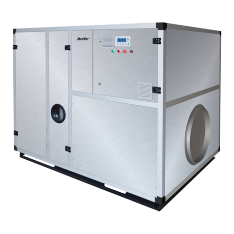
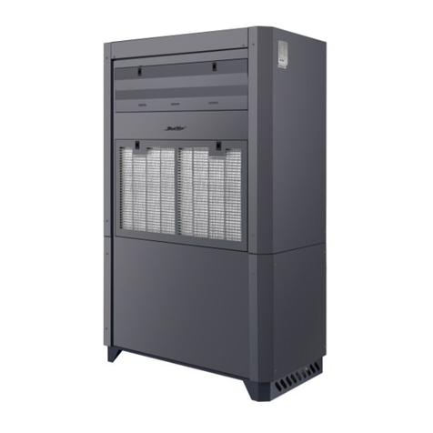
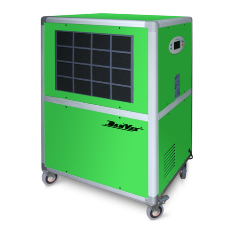
DanVex DD Series User manual

Page 1 of 39
DanVex’s
DD, DD-F, DD-FS, DD-FSR Series
DUCTED DEHUMIDIFIER
User’s Manual
KEEP THESE INSTRUCTIONS FOR FUTURE REFERENCE
Thank you for choosing our dehumidifier. This owner’s manual will provide you with
valuable information necessary for the proper care and maintenance of your new
dehumidifier. Please take a few moments to read the instructions thoroughly and
familiarize with all the operational aspects of this dehumidifier. This unit removes
excessive moisture from the air to create a more comfortable environment.

Page 2 of 39
Table of Contents
Foreword ..................................................................................................................4
Purpose ...................................................................................................................................................... 4
Content ...................................................................................................................................................... 4
Rights Reserved ......................................................................................................................................... 4
1. SAFETY INTRODUCTION ........................................................................................5
1.1 Safety ................................................................................................................................................... 5
1.2 Applications: ........................................................................................................................................ 5
1.3 Manual Content ................................................................................................................................... 5
2. INTRODUCTIONS OF DEVICE .................................................................................6
2.1 Standards ............................................................................................................................................. 6
2.2 Structure .............................................................................................................................................. 6
2.2.1 Housing and body ..................................................................................................................... 6
2.2.2 Inlet / Outlet Air Panel .............................................................................................................. 6
2.2.3 Refrigeration system ................................................................................................................. 6
2.2.4 Compressor ............................................................................................................................... 6
2.2.5 Throttling device system ........................................................................................................... 6
2.2.6 Protection devices .................................................................................................................... 7
2.2.7 Product Diagram ....................................................................................................................... 7
3. INSTALLATIONS...................................................................................................... 9
3.1 Brief introduction ................................................................................................................................. 9
3.2 Delivery and storage ............................................................................................................................ 9
3.3 Inspection before installation .............................................................................................................. 9
3.4 Moving machine .................................................................................................................................. 9
3.5 Installation Location ............................................................................................................................. 9
3.6 Ground/Base ...................................................................................................................................... 10
3.7 Ducting Connection ........................................................................................................................... 10
3.8 Ducting Connection Diagram (example) ............................................................................................. 11
3.9 Service Access Space Allocation ........................................................................................................ 12
3.10 Drain pipe connection ...................................................................................................................... 13
3.11 Electrical connection ........................................................................................................................ 14
3.12 Sensitive elements connection ........................................................................................................ 14
3.13 Wiring Diagram: DanVex DD Wiring diagrams the dehumidifier pasted on the body, and are available in
the appendix of this manual. ................................................................................................................... 14
3.14 Wiring Diagram: DanVex DD-F Wiring diagrams the dehumidifier pasted on the body, and are available in
the appendix of this manual. ................................................................................................................... 14
3.15 Machine Picture Diagram ................................................................................................................ 15
4. OPERATIONS .......................................................................................................17

Page 3 of 39
4.1 Button Controller Module .................................................................................................................. 17
4.3 Safety Cautions .................................................................................................................................. 23
5 MAINTENANCES...................................................................................................24
5.1 Maintenance introduction ................................................................................................................. 24
5.2 Filter ................................................................................................................................................... 24
5.3 Fan Motor .......................................................................................................................................... 24
5.4.1 Maintenance during start of usage season ............................................................................. 25
5.4.2 Maintenance during end of usage season .............................................................................. 25
5.4.3 Maintenance of key components ........................................................................................... 25
5.4.4 Maintenance procedures ........................................................................................................ 25
5.5 Inspection and maintenance procedures .......................................................................................... 27
6. Troubleshooting ..................................................................................................29
7 APPENDIX.............................................................................................................32
7.1 Warranty Information ........................................................................................................................ 32
7.2 Wiring Diagram ............................................................................................................................... 33

Page 4 of 39
Foreword
Purpose
This manual provides all the information about this precise dehumidifier, including the structure,
installation, principle, work process and the detailed operating instruction is provided.
Content
Dehumidifying control system, operating ways, maintain, and regular failure and failure elimination
Rights Reserved
We reserve the rights of updating/explaining all contents of manual involved.
Warning!
All electrical connections works must be done by local professionals, according to relevant
provisions to operate, or some loss of life, personal injury, property loss may be happened. Please
read through the manual before electrical works, avoiding any fault operation that causing loss of
life or property. Please contact the supplier or the manufacturer if there are any issues arises that
are not stated in this manual.

Page 5 of 39
1. SAFETY INTRODUCTION
1.1 Safety
This series of dehumidifier is in conformance with all provisions of European security requirements
and standards, the safety of worker and equipment are taken into care while in design and
manufacture process. In each section of the manual, there are safety information and explicitly
pointed out operation that may causes danger. And it is mark with "Danger" as a warning sign.
This manual provides information on the appropriate ways of operating the dehumidifier. It
shall serve as a guideline only and are not liable for any personal responsibility or meeting local
safety regulations. During the installation and operation of the equipment, everyone shall bear the
liability as listed below:
• To ensure the equipment in good condition according the description provided in this manual;
• Do care the safety of yourself and others;
• Dehumidifier should be operated and maintenance by related qualification professionals;
• Do not install dehumidifier around the explosive protection devices;
• Cut off the power before open any cover in the housing;
• When the operation ended, please allow the equipment to cool down at least 15 minutes
before begin the maintenance service;
• The machine panel should be closed at all time if maintenance work is not carried out;
• Dehumidifier is limited to atmospheric pressure condition to dehumidify;
• Filter device must be installed before using the dehumidifier;
• Removing or deleting the marks/declares/notes in the dehumidifier is prohibited;
• The manual should be kept well for using in the future;
• Original spare parts should be used for any replacement;
• The written permission from manufacture must be needed before repairing the dehumidifier;
1.2 Applications:
The dehumidifiers are widely used in hotels, office buildings, hospitals, commercial, research
institutions and other applicable places. Its working principle is to remove excess moisture by drying
the air under normal atmospheric pressure. Its working humidity range is from 40%-90% (the
humidity can be reduced to 40% at most), and working temp range is 5 °C to 35 °C. If the ambient
operating temperature is beyond this range, the dehumidify capacity will be affected, this issue
does not reflect on the quality of the equipment itself.
1.3 Manual Content
This manual content includes most info about installation, operation, maintenance, and failure
analysis and others.
Note: this manual is applicable to other precise dehumidifiers of the same range.

Page 6 of 39
2. INTRODUCTIONS OF DEVICE
2.1 Standards
The design meets IEC protection class IP 45 requirements.
2.2 Structure
2.2.1 Housing and body
Adopts steel frame structure, compact, strong, robust, and the defrosting technology effectively
preventing the "frozen" issue;
Easy to open / access panel for replacing filter
Water tray equipped ensures that all condensate water drain out, preventing water stagnation.
2.2.2 Inlet / Outlet Air Panel
Removable filter is equipped in each air inlet;
Centrifugal fan with steel volute and blades, high efficiency and low noise.
2.2.3 Refrigeration system
The design of the dehumidifier uses energy-saving heat exchanger. It can effectively regulate the
fluid flow volume, maximizing freezing capacity, and ensuring compressor operates well.
Meanwhile, dried filter was introduced in this system to prevents clogging/impurities in
expansion valve or capillary
Patented defrosting structure, it brings stable operation of refrigeration system
Hydrophilic membrane fin (heat exchanger), heat transfer efficiency increases by 20%. Good
insulation material also increases insulating effect by 15%
2.2.4 Compressor
Compressor is the core part of this dehumidifier. It directly affects dehumidifier performance. It
is the heart of this dehumidifier, provides powers for whole system. Our dehumidifier is built
with reliable and high efficiency compressors.
2.2.5 Throttling device system
Throttling device system is one of four vital items in the refrigeration systems. It will reduce the
liquid refrigerant (coming from condenser) high pressure, make the refrigerant absorb heat
under low pressure (low temp) while vaporization happen. It’s ensuring high pressure in
condenser and low pressure in evaporator. As a result, the loss of cooling capacity is reduced
thus ensuring higher efficiency. It also prevents over-heating on the compressor.

Page 7 of 39
2.2.6 Protection devices
Dehumidifier controller is specially designed according the operation of the dehumidifier
and it is designed to optimize its performance. Motor overload and short circuit protection is
included as well.
Start-up delay protection: If the dehumidifier is power off during operation, it will take 3
minutes to turn on again. This is a delay protection for protecting the compressor.
Shutdown delay protection: When the dehumidifier is power off, the fans will keep running
for 3 minutes, to cool down the dehumidifier thus reducing the internal heat of the
dehumidifier.
Fans operation mode: The fan will run and stop according to the RH setpoint.
High temperature protection: Prevent the compressor running continuously at high
temperatures;
Low pressure protection: Prevents the dehumidifier running without refrigerant to avoid
compressor from being overload.
2.2.7 Product Diagram
DD Series

Page 8 of 39
DD - F Series

Page 9 of 39
3. INSTALLATIONS
3.1 Brief introduction
Ceiling Mounted dehumidifier can be installed in many places, depending on the requirements of
owners. It can also integrate with current ventilation system via duct system. This chapter records
info about preparation work, and installation work and etc. Please serve it as a guide before
installation.
3.2 Delivery and storage
To ensure the quality and reliability of each dehumidifier, it has been thoroughly tested in factory.
If dehumidifier has to be stored for a while prior to installation, please take notes of the following:
①Keeping transport package in good condition;
②Avoiding physical damage;
③Dehumidifier should be stored indoor and covered properly to prevent dust, frost and rain
intrusion.
3.3 Inspection before installation
Unpack package and check machine: If any damage is found, please contact supplier /
manufacturer.
3.4 Moving machine
Please check the dehumidifier weight before any loading / unloading. For moving the unit of a
longer distance, it is advice to use proper equipment (trolley or forklift) to move the goods. It should
be take note that the dehumidifier shall be lifted up properly and the lifting point should be away
from the motor, control system and exposed pipe to avoid any damages onto the equipment.
3.5 Installation Location
For best operation and maintenance service, it is advice to install the dehumidifier indoor / inside of
room with extra space for routine maintenance/checking in order to prevent condensation inside
the dehumidifier, the unit should not be exposed to environment where temperature is below the

Page 10 of 39
process air’s dew point. Please place the device near to power source.
NOTE: Please provide enough space around the dehumidifier for troubleshooting and
maintenance service purpose.
3.6 Ground/Base
Dehumidifier must be installed horizontally with well-balanced level. Please use horizontal ruler to
measure the level during installation.
3.7 Ducting Connection
The dimension of ducting for inlet and outlet air should be in line with ISO7807 recommended
values. Ducting should be connected with the connection part on flange; meanwhile, the screw bolt
is limited to within 20mm. While connecting the ducting, some notes as below:
x In order to reduce loss of static pressure, do the best to shorten the length of the ducting;
x To ensure performance of machine, all rigid (galvanized) ducting fittings are required to have
air-tightness;
x The ducting should have a good capacity of thermal insulation, then the phenomenon of
moisture condensation inside pipe wall will be avoided, and the pipeline won't be corroded;
x To reduce noise and vibration transmitted along the pipes, the good quality, soft and strong
airtight adapting pieces should be used in the joint parts;

Page 11 of 39
3.8 Ducting Connection Diagram (example)

Page 12 of 39
3.9 Service Access Space Allocation
Please allocate the space require as per the table for access to service the unit.
Model
Service Area
Void Area / No Blockage
A
B
E
D
DD -26 / 26F
400mm
490mm
100mm
100mm
DD -36 / 36F
500mm
600mm
100mm
100mm
DD -56 / 56F
500mm
600mm
100mm
100mm
DD -96 / 96F
600mm
650mm
100mm
100mm
DD -136 / 136F
600mm
650mm
100mm
100mm
DD -168 / 168F
500mm
500mm
270mm
100mm
DD -240 / 240F
500mm
500mm
270mm
100mm
DD -480 / 480F
500mm
600mm
370mm
100mm
DD-720/720F/960/960F
500mm
600mm
370mm
100mm

Page 13 of 39
3.10 Drain pipe connection
Drain pipe is a transparent hose, please connect it as per the drawing as below:
It is strongly advised to install a U-Trap with PVC pipe or any other pipe that are suitable. This would
help to allow the condensate water flow out smoothly.

Page 14 of 39
3.11 Electrical connection
Be careful! All electrical connection works must meet local electrical equipment installation
standards, done by qualified professionals.
It is forbidden to connect the power supply beyond the specified voltage and frequency;
Before the connecting the power supply, the electrical point should be checked to ensure that
its voltage and frequency fluctuation does not go beyond ±10%;
Unit must be grounded and turn off power during checking work.
3.12 Sensitive elements connection
The installation of temperature and humidity detection devices (controller) should follow the
requirements as below˖
Temperature and humidity detection devices should be installed above ground 1m - 1.5m, to
ensure the device can detect the humidity of the dehumidifying area;
Detection device should be installed away from dry air or wet air or airflow from outside;
Temperature and humidity detectors should stay away from cooling equipment,
do not directly exposed to sunshine place, as the change of the temperature will affect the
actual assessment;
External control system must be compatible with the low voltage control circuit of
dehumidification equipment.
3.13 Wiring Diagram: DanVex DD
Wiring diagrams the dehumidifier pasted on the body, and are available in the appendix of this
manual.
3.14 Wiring Diagram: DanVex DD-F
Wiring diagrams the dehumidifier pasted on the body, and are available in the appendix of this
manual.

Page 15 of 39
3.15 Machine Picture Diagram
EC Fan
Compressor
Heat
Exchanger
Filters
Wiring
Terminal
Green Connector & Controller
To connect between Machine and Controller
3 Phase
Protector
&
Contactor

Page 16 of 39
P
Pa
P
P
Pa
P
P
P
P
P
Pa
P
P
Pa
P
Pa
P
P
P
P
P
Pa
Pa
Pa
P
Pa
Pa
P
P
P
P
P
P
P
Pa
Pa
P
P
P
P
P
P
Pa
Pa
Pa
Pa
Pa
P
P
Pa
P
P
P
Pa
Pa
a
Pa
PaPa
P
P
P
P
Pa
P
P
P
P
P
P
P
P
P
P
P
P
ge
g
ge
ge
ge
ge
ge
ge
ge
ge
g
g
g
g
g
g
g
g
g
ge
g
g
g
g
g
ge
ge
g
g
g
g
g
ge
g
g
g
ge
ge
g
g
g
g
g
g
ge
g
ge
e
g
g
e
e
e
e
e
e
e
ge
e
e
e
e
ge
g
g
g
g
g
g
g
g
g
g
g
g
g
g
g
g
g
g
g
1
1
1
16
1
1
6
16
1
1
6
1
1
6
16
16
6
16
1
1
1
1
1
1
1
1
1
1
1
1
1
1
1
1
1
1
1
1
1
of
39
Fresh Air Damper and
Return Air Inlet
-
For DD-F Series
Return Air Inlet -
DD Series
Supply Air Outlet
DD Series
DD-F Series

Page 17 of 39
4. OPERATIONS
4.1 Button Controller Module
This unit of controller is built-in with Honeywell temperature and humidity sensor to monitor indoor
temperature and humidity in real time. The controller comes with physical buttons for functional
and easy operation. The controller provides functions to control the machine On/Off, Humidity
Setting, Fresh Air Valve On/Off, Adjust Fan Speed (depending on models and available fan settings)
and many other functions. Please read the manual carefully before operation.
1. On/Off button
2. Mode switching button
3. Fresh air valve on/off button
4. Operation setting button
5. Time setting button
6. UV light sterilization
7. Anions purification button
8. Up value button
9. Down value button

Page 18 of 39
Basic Functions:
1. RS485 communication connection (2-wires) is available. It uses MODBUS protocol to
communicate.
2. Temperature and Humidity display and setting.
3. Wireless communication function (WIFI). Press for few seconds, WIFI icon will appear and
flashing, at the same time the IMEI number will appear, after a minute of no activity it will auto
log off.
4. The on/off button will signal the machine to turn on and off. After turning on the machine, if
there is no further activity, the controller backlight will dim after 60 seconds. Press any key to
turn on the backlight. Every time when the machine is turn on, the fan will start first, follow by
the compressor after 10 seconds. When the machine is turn off, the compressor will stop first,
follow by the fan after 3 minutes. Please allow an interval time of 3 minute to turn on the
machine, after it is being turn off. When the compressor is turn on, the dehumidifying icon will
appear at the upper right of the screen. When turning off the machine, it is to note that the air
valve should be closed as well.
5. To quickly set the humidity settings, user can press or button and hold for a second
which will immediately set the humidity value. When quick press or button it will help
to adjust the fan speed. Alternatively, these functions can also be set by pressing the Operation
Setting button to enter the Setting Menu.
6. During Humidification function, the fan will operate at high speed.
7. Auto Mode Function
a) Humidification: during humidifying operation, when the ambient humidity level is below the
setpoint, it will turn on the humidifier. (In the System Setup, the humidifying function must
be turned on in order to use humidification function – for Humidifier machine).
b) Dehumidification: during dehumidifying operation, when the ambient humidity level is
above the setpoint, it will turn on the compressor to start dehumidifying.
c) When the ambient humidity level is within the setpoint level, the humidifying or
dehumidifying function will turn off.
d) When the Humidifying function is turn On, the Dehumidifying function will automatically
shut off. The same condition will apply during Dehumidifying function.
8. Filter Timer function allows to set filter replacement reminder based on operation hour. E.g. if
the timer is set at 2000 hours, when the machine run for 2000 hours, the filter replacement
icon will appear on the controller. Press and together at the same time and hold for few
second to reset the filter timer after the filter is replaced. Filter replacement timer by default is
1000 hour, maximum is 9000 hour, each increment is 200 hour.

Page 19 of 39
9. Auto / Manual Mode. Press to switch between Auto or Manual mode.
- Auto mode: during this mode, it will automatically turn on and off the dehumidifying
function based on setpoint value.
- Manual mode: Press and hold for few second, it will start the dehumidifying function.
Press and hold for few second again, it will turn off the dehumidifying function.
10. Press to open / off fresh air valve, the icon as below will show to indicate different
setting.
means double flow fresh air valve is open (for certain models);
means single fresh air valve is open (for certain models);
means fresh air valve is close and the air is internal re-circulate.
11. The controller will beep once when the machine is powered on.
12. During auto mode, the compressor and the fan will work automatically. If switch to manual
mode, the compressor will not turn off immediately, it will remain the same condition during
auto mode before changing to manual mode.
13. During manual mode, press and hold for few second, it will turn on the dehumidifying
function. Press UV button and hold for few seconds will turn on the humidifying function.
However, at each time only one function can be turned on, either Dehumidifying or Humidifying
function at one time. During manual mode, the dehumidifying and humidifying function will not
turn on / off according to setpoint.
14. Ventilation mode: during this mode, only the fan is running. Neither dehumidifying nor
humidifying is functioning.
15. Under any circumstances, the fan shall run first for 20 seconds (preset setting is 10 seconds).
When the compressor stops and restart again, it will require a delay startup of 3 minute to
protect the compressor.
16. Filter replacement time is preset at 1000 hour. Once it reaches the preset time, the filter icon
will appear, and it will automatically lock all the function of the controller. Once the filter is
replaced and the Filter timer is reset, only then the controller function will be unlocked. The

Page 20 of 39
first replacement timer is 1000 hours, follow by second replacement is 4000 hours, third
replacement is 6000 hours and the next following will be 6000 hours interval.
Display Interface:
1. The controller will resume to the same state on the next startup regardless due to power failure
or manual shutdown of power.
2. During setting of any parameter value, when the value is blinking it indicating the value can be
adjusted.
3. The timer switch icon by default is in white color, which indicate it is not activated. Press on the
Time setting button to turn on the Timer ON function, press again to turn on the Timer OFF
function, if press for another time, it will turn on the Timer ON and OFF functions. The next
following press will turn off the Timer ON and OFF functions. When the Timer ON or OFF
function is activated, the timer switch icon will appear at the same time. Press and hold the
clock button to set the Timer ON value. Then press and to set. Once is set, press the
setting button to confirm and continue with the next following setting. Press and hold the
Time setting button to exit and confirm on the set time.
4. The temperature indicator shows the current indoor temperature, depending on the location of
the controller is installed.
5. The humidity indicator shows the current indoor humidity level, depending on the location of
the controller is installed.
6. The upper left corner shows the current fan speed. The fan level indicator turns yellow according
to the fan speed.
7. The WIFI icon is at the upper right corner. By default, it is inactive (gray), it will turn white when
the WIFI function is turn on.
8. The second upper right corner icon indicating the supply air mode (Double or Single Flow
Fresh Air, and Re-circulation mode)
9. The third upper right corner icon indicating the dehumidifying function (also indicate
compressor is on/off).
This manual suits for next models
23
Table of contents
Other DanVex Dehumidifier manuals

DanVex
DanVex DEH-400P User manual

DanVex
DanVex DEH-1200P User manual

DanVex
DanVex DEH-600P User manual

DanVex
DanVex DEH-900i User manual

DanVex
DanVex DEH-290h User manual

DanVex
DanVex DEH-3K User manual

DanVex
DanVex AD-3000 User manual

DanVex
DanVex AD-200 User manual

DanVex
DanVex DEH-1600i User manual

DanVex
DanVex AD-10000 User manual