DanVex AD-200 User manual

Manual
Desiccant dehumidifiers
AD-200 / AD-400 / AD-550
rev. 2.01

1www.danvex.
SAVE THIS MANUAL FOR FUTURE REFERENCE
CONTENT
Introduction ............................................................................................................................................................3
Purpose .............................................................................................................................................................3
Content .............................................................................................................................................................3
Copyright .........................................................................................................................................................3
1.
SAFETY AND APPLICATION .........................................................................................................................4
1.1 Safety of use ............................................................................................................................................4
1.2 Applications .............................................................................................................................................5
2 DEVICE INFORMATION ..................................................................................................................................6
2.1 Standards ..................................................................................................................................................6
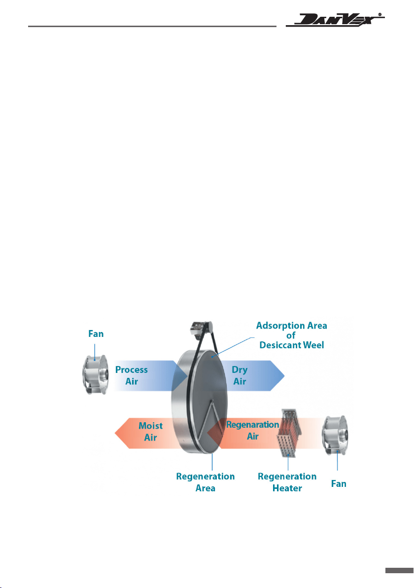
2.2 How it works ............................................................................................................................................6
2.3 Construction ............................................................................................................................................7
2.3.1 Enclosure ................................................................................................................................................7
2.3.2 Conveying air circuit ..........................................................................................................................7
2.3.3 Regeneration air circuit .....................................................................................................................7
2.3.4 Rotor ........................................................................................................................................................7
2.3.5 Rotor drive .............................................................................................................................................7
2.3.6 Safety devices .......................................................................................................................................7
3 INSTALLATION .................................................................................................................................................8
3.1 Introduction ..............................................................................................................................................8
3.2 Transport and storage ...........................................................................................................................8
3.3 Checking before installation ...............................................................................................................8
3.4 Moving ........................................................................................................................................................8
3.5 Place of installation and its arrangement ......................................................................................8
3.6 Support/ Foundation .............................................................................................................................8
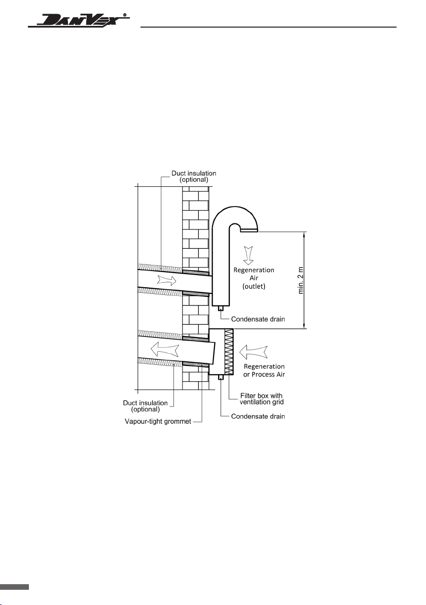
3.7 Connecting to air ducts .........................................................................................................................8
3.8 Electrical connection .............................................................................................................................12
3.9 Connecting external humidity sensors ...........................................................................................12
3.10 Checking before starting ...................................................................................................................13

2www.danvex.
4 OPERATION .....................................................................................................................................................13
4.1 Elements of the control and monitoring panel ..........................................................................13
4.2 Humidity controller interface and settings ..................................................................................14
4.3 Algorithm of operation of the dryer components .....................................................................16
5 MAINTENANCE ................................................................................................................................................17
5.1 Introduction .............................................................................................................................................17
5.2 Filters ..........................................................................................................................................................17
5.3 Rotor ...........................................................................................................................................................17
5.4 Gear motor ...............................................................................................................................................17
5.5 Heating device .......................................................................................................................................17
5.6 Drive belt .................................................................................................................................................17
6 TROUBLESHOOTING ....................................................................................................................................18
6.1 Inspection and maintenance intervals .........................................................................................18
6.2 Troubleshooting ...................................................................................................................................19
7 CHARACTERISTICS ......................................................................................................................................20
8 OVERALL AND MOUNTING DIMENSIONS .........................................................................................21
9 ELECTRICAL WIRING DIAGRAM .............................................................................................................23

3www.danvex.
Introduction
Purpose
This user manual contains complete information about the dehumidifier model you have
purchased, including details of its design, principle of operation, installation and operation
instructions.
Content
General information about the management of the dehumidification process, the principle
of operation and maintenance standards, system errors, diagnostics and troubleshooting.
Copyright
We reserve all rights to update and clarify the information contained in this manual.
Desiccant dehumidifiers
AD-200 / AD-400 / AD-550
Manufactured by DanVex (Finland)
www.danvex.fi

4www.danvex.
Warning!!!
All electrical connections must be carried out by local specialists in accordance with current
standards, otherwise there is a risk of death, injury, equipment damage and property damage!
Before starting work on electrical equipment, read this manual in order to avoid errors,
which could result in death or equipment damage
1 SAFETY ANDAPPLICATION
1.1 Safety of use
All models of dehumidifiers in this series are manufactured in compliance with the requirements
of European safety standards and current regulations; the requirements for the safety of the operator
and equipment were taken into account during design and production. Each section of this manual
provides safety information and describes in detail the circumstances that can lead to abnormal
situations. Such information is marked with a warning label "dangerous".
This manual also provides complete information on how to maintain the dehumidifier.
It is for guidance only and does not remove the operator's responsibility for compliance
with personal safety requirements at work and local safety standards.
During the installation and operation of equipment,
each employee must follow the instructions below:
•follow the descriptions and instructions in this manual to ensure the protection
of the equipment;
•ensure the safety of yourself and others;
•the unit must be operated and maintained by professional technicians;
•electrical components must be serviced by authorized electricians;
•it is forbidden to install the dehumidifier in rooms equipped with explosion-proof devices;
•before opening any service panel, disconnect the device from the main power supply;
•the device must be cooled down for at least 15 minutes before maintenance;
•if no maintenance is being performed, the maintenance panel must be closed;
•the unit can only dehumidify at atmospheric pressure;
•do not use the unit without a filter; if the filter is not installed, the rotor will become dirty
and stop working;
•it is forbidden to remove warning signs on the device;
•this manual must be kept with care;
•original spare parts must be used;
•written permission must be obtained for any adjustments or modifications.

5www.danvex.
1.2 Applications
The AD series dehumidifiers use a silica-gel coated composite adsorption rotor and are capable
of effectively dehumidifying air at atmospheric pressure in a relative humidity range of 2 to 100%
and an operating temperature range of -20°C to +50°C.
Adsorption dryers are widely used in the following areas:
•rooms and areas with low temperatures and low humidity;
•areas with relative humidity below 35% and low dew point;
•process air preparation systems;
•single pass airflow systems;
•manufacturing, packaging, storage, testing and research of pharmaceutical
products;
•production and packaging of confectionery and food products;
•pneumatic conveying of powder materials;
•production of electronics;
•archival repositories of photographic materials and films;
•refrigerated warehouses;
•seed storages;
•"clean" rooms;
•pumping stations;
•injection molding production areas;
•ice areas;
•drying of tanks and ship holds;
•conservation of turbines in the prevention of corrosion at power plants
•and etc.

6www.danvex.
2 DEVICE INFORMATION
2.1 Standards
The design of the dehumidifier complies with protection class IP 44, IEC standard.
2.2 How it works
The main component of the installation is a honeycomb rotor, consisting of a special ceramic
fiber and active silica gel. The two sides of the rotor are separated by special hermetic seals into
two zones: the working zone, which is 3/4 of the rotor surface, and the regeneration zone, 1/4
of the rotor surface. When moist working air passes through the filter into the rotor, the moisture
from the air is absorbed by the dehumidifying working sector of the rotor, and the dehumidified
air is expelled from the other side of the rotor by the fan. At the same time, the regeneration air
passes through the filter, heats up and enters the regeneration sector of the rotor. In this zone,
the heated regeneration air removes from the rotor the moisture previously adsorbed
by the silica gel, which is then removed in the form of steam from the dryer and into the street.
Schematic diagram of the operation of an adsorption dryer
Note:
the diagram does not show the obligatory filters for working and regeneration air

7www.danvex.
2.3 Construction
2.3.1 Hull
•compact stainless steel frame construction for corrosion resistance and effective insulation
against condensation;
•removable panels providing access to internal components;
•well-designed layout and selection of units to ensure minimum head drop.
2.3.2 Conveying air circuit
•at the air inlet there is a filter class G3 with the possibility of cleaning;
•centrifugal high efficiency low noise fan.
2.3.3 Regeneration air circuit
•at the air inlet there is a filter class G3 with the possibility of cleaning;
•centrifugal, high-efficiency, low-noise, forward-curved fan.
•heating section using PTC heaters.
2.3.4 Rotor
•The rotor is the main part of the dryer. Its characteristics directly affect the performance
and operation of the dehumidifier. The rotor is made of a special heat- resistant composite
material. The composite material is a corrugated structure filled with a highly effective
desiccant, forming many small air flow channels, contacting the air with a large area
and increasing the dehumidification efficiency.
2.3.5 Rotor drive
•Rotation of the rotor at the desired speed can be achieved using an electric motor
with a geared motor and a belt drive. The belt is located on the outer rim of the rotor
and is driven by a geared motor pulley.
•The belt tensioner maintains proper belt tension to prevent belt slip page. The direction
of rotation of the rotor and the condition of the belt need to be checked regularly.
2.3.6 Safety devices
•Motor protection against overload and short circuit: fan motors for working and regeneration
air, rotor drive motor have overload and short circuit protection functions.
•Shutdown protection: When the dryer is switched off under normal conditions,
the regeneration fan continues to run until the regeneration heater and rotor have cooled
below 60°С.

8www.danvex.
3 Installation
3.1 Introduction
The information in this chapter describes the work required to install the device.
Careful familiarization before installation will help you properly organize the installation work.
3.2 Transport and storage
To guarantee the quality and reliability of each dryer, we test all devices at the factory.
If the dryer is in storage:
•keep the original packaging;
•avoid physical damage to the equipment;
•store the dehumidifier indoors, protect it from dust, moisture and frost.
3.3 Check before installation
Remove the packaging and check the equipment: if damage is found, contact the supplier/
manufacturer.
3.4 Moving
Before starting loading and unloading, check the weight of the equipment. It is recommended
to use lifting devices (stacker or forklift) to move the equipment. Please note that the dryer must
only be lifted properly to avoid tipping over and damage.
3.5 Place of installation and its arrangement
The dehumidifier is designed for indoor and outdoor use. To ensure proper maintenance for
opening the service panels, it is recommended that when installing the dryer, leave a free space
on all sides of about 800 mm.
The minimum width of the service space must not be less than the width of the dryer.
The unit cannot be placed in an explosive place, and also cannot work with air containing
explosive substances.
For outdoor installation, measures must be taken to protect against rain, snow, dust
3.6 Support/ foundation
The dehumidifier should be installed in a horizontal position on a level ground or platform.
The installation location must have sufficient bearing capacity to support the weight of the
installation. It is recommended to fix the dehumidifier to the base. Use a building level during
installation.
3.7 Duct connection
The dimensions of the process and regeneration air ducts must comply with the recommendations
of the ISO7807 standard. The air ducts are connected using an appropriate flange, while the bolt
diameter should not exceed 20 mm. When connecting to the duct, consider the following factors:
•to reduce static pressure losses and not reduce dehumidification performance, shorten
the length of the air ducts if possible;

9www.danvex.
•to guarantee the high performance of the dryer, all rigid (galvanized) duct flanges must
be air tight;
•the air duct must have good thermal insulation to protect the inner metal part of the air
duct from condensation and hence from corrosion;
•to reduce the level of noise and vibration from the air passing through the duct, use
strong and soft, air tight adapters;
•the air duct leading directly to the dryer must be fully anchored to reduce stress
and pressure on the flanges from the weight of the duct.
If air is taken into the dehumidifier from outside, the air inlet must be sufficiently high above
the ground or equipped with an additional inlet filter to prevent dust and debris from being
sucked in. The inlet must be away from possible sources of pollution such as exhaust gases,
steam and harmful gases.
To prevent humid air at the outlet from humidifying the process air at the inlet, it is necessary
to separate the inlet of external process air at a distance of at least 2 m from the humid air outlet.
The design of the duct must prevent the penetration of rain and snow.
The regeneration outlet air is hot and humid. Condensation from it can easily form on the inside
wall of the duct, so the duct must be laid with a downward slope away from the unit. In addition,
a condensate drain hole with a diameter of 10 mm must be installed at the lowest point of the
duct to prevent accumulation and stagnation of water.

10 www.danvex.
The humid regeneration air duct must be insulated to prevent condensation on the inner wall
of the piping when the dew point temperature of the air in the piping is higher than the outdoor
air temperature, which can cause corrosion and water accumulation in the piping.
The dry air outlet of the dehumidifier can be equipped with a control valve that can be used
to control the operation of the dehumidifier. If you want dry air to contain lower humidity,
you must install a control valve at the dry air outlet. If maximum dehumidification capacity
is not required, install a damp air outlet damper.
3.7.1 Connecting the air recirculation ducts
The unit can be installed in a room or a separate room where dehumidification is required.
For best performance, the fan outlet must be equipped with a diffuser.
3.7.2 Connecting the regeneration air outlet ducts
Moist air must be vented outside. The length of the duct should be as short as possible
to minimize the chance of damp air condensing. The duct must be slightly inclined towards
the outlet to prevent condensate from flowing back into the dryer. If the regeneration duct
is particularly long or must be installed vertically, it must be thermally insulated and a drain
point provided at its lowest position. The air duct outlet must be equipped with a metal grill
or mesh to prevent debris from entering.
3.7.3 Connecting the regeneration air inlet ducts
It is desirable to minimize the length of the regeneration air inlet duct as much as possible.
To prevent debris from entering the air duct, equip a metal mesh at the inlet. In some conditions,
other ducts may be used for the connection, and an air flow control valve must be installed
on the duct to ensure correct adjustment of the regeneration air flow during the trial run.
3.7.4 Installing the dehumidifier in the room to be dehumidified
If the unit is installed in a room requiring dehumidification, the process air inlet does not
necessarily require a duct connection. A protective mesh is required at the process air inlet.
The dry air outlet must be ducted and separated from the air inlet of the dehumidifier
so that the dry air can be evenly distributed throughout the room.
Air intake for regeneration should be carried out outside the room to be dried. Otherwise,
due to rarefaction, an uncontrolled suction of moist air from the street or from neighboring
rooms is possible into the room being dried. The regeneration air must be discharged outside.

11www.danvex.
3.7.5 Installing the dehumidifier outside the room to be dehumidified
When installing the dehumidifier in a separate technical room, at least three of the four inlets
and outlets of the unit must be connected to air ducts.
The working air ducts must take moist air from the room to be dried. The dehumidified air
at the dehumidifier outlet and before being supplied through the air duct to the dehumidified
room can be subjected to post-processing (for example, cooling by a third- party device) or sent
immediately back to the dehumidified room without preparation.
Air intake for regeneration can be carried out both from the street and from the technical room.
The release of regeneration air must be carried out to the street.
An air volume control valve can be installed on the process air duct to control the flow of dry air.
Indoor installation
The regenerative air inlet and outlet must be located outside the circuit to be dried. Dry air must
be evenly distributed in the room to be dried, no duct connection to the process air inlet is required.
Installation diagram inside the dehumidification circuit
•If the regeneration air inlet and the regeneration air outlet are connected to the same area, the duct
sockets must be at least 2 meters apart to avoid hot and humid air entering the regeneration air inlet.
•The regeneration air outlet must have a certain slope to ensure that hot and humid air can be evacuated
smoothly.
•The need for ducting for process air inlet and outlet depends on the size of the interior space
and the distance from the dehumidified area to the dryer.
•If the room temperature is low, such as in cold stores, the dehumidifier and air water must be thermally
insulated to prevent condensation
Outdoor installation
The inlet and outlet of regenerative air must be separated in space. The air ducts for the supply
of dehumidified air and the intake of dried air must be connected to the dehumidification zone
(room), but the places of intake and supply must be separated.

12 www.danvex.
Installation diagram outside the dehumidification circuit
•If the regeneration air inlet and the regeneration air outlet are connected to the same area, the duct
sockets must be at least 2 meters apart to avoid hot and humid air entering the regeneration air inlet.
•The regeneration air outlet must have a certain slope to ensure that hot and humid air can be evacuated
smoothly.
•The need for ducting for process air inlet and outlet depends on the size of the interior space
and the distance from the dehumidified area to the dryer.
•If the room temperature is low, such as in cold stores, the dehumidifier and air water must be thermally
insulated to prevent condensation.
3.8 Electrical connection
Be careful! All work on electrical equipment must be carried out in accordance
with the standards of the country in which the equipment is used,
and only by qualified experts!
•It is forbidden to connect the dehumidifier to the mains, the power and frequency of which
are outside the nominal values of the dehumidifier;
•Before connecting to the power supply, check that the voltage and frequency fluctuations
at the connection point do not exceed ±10%;
•The equipment must be earthed and a power disconnect must be provided to ensure
that the device is disconnected during inspection and maintenance.
•The fuse rating of the power supply must match the power and type of the device.
The fuse must be installed near the device. The choice of power cable and main fuse
must match the operating power of the dehumidifier.
3.9 Connecting external humidity sensors
The electrical wiring for the sensors can be pre-wired and provided with terminals for connecting
external control components.

13www.danvex.
4 OPERATION
4.1 Elements of the control and monitoring panel
The dehumidifier is equipped with an automatic control system that ensures uninterrupted
operation in the selected mode, as well as ease of operation and control.
The dehumidifier has 2 modes of operation, the choice of which is carried out by the operator
using 3 position switch (Rocker Switch) on the control panel:
When installing a temperature sensor temperature and humidity (sensing element),
its mounting position must comply with the following requirements:
•Temperature and humidity sensors should be installed at a distance of 1-1.5 m from
the ground so that the sensor measures the humidity level in the area being dried;
•Sensors should be installed away from dry/moist air flow or air flow from the environment;
•Temperature and humidity sensors should be installed away from refrigeration equipment;
•Do not install the sensors in a place exposed to direct sunlight, as temperature changes
may affect the measurement process.
The scheme for connecting an external temperature and humidity sensor to the controller
is shown in the general wiring diagram of the installation. Characteristics of sensors and terminals
for connection are also specified in the section with description of controller terminals.
3.10 Check before starting
All work on electrical equipment must be carried out by qualified personnel
who are aware of the potential risks such as electric shock and heat
Before the first start-up, some checks must be carried out, and the power supply to the unit must
be switched off.
Order and sequence of actions:
•Make sure the dehumidifier is powered off and that the dehumidifier's main switch
is in the OFF position.
•Open the dryer's service panels and check that there are no foreign objects in the dryer.
•Check that all air dampers are open and that the passages are clean and free.
•Make sure the air filters are clean and installed.
•Turn, if possible, the fan impellers by hand and make sure they can turn freely.
•Check the internal fuse.
•Close the service panels and connect the dehumidifier to the mains.

14 www.danvex.
•MAN - manual control mode. The dehumidifier operates
continuously without the humidity controller being activated
and until it is turned off by the operator.
•AUTO - automatic control mode. In this mode, the dehumidifier
is automatically controlled by the humidity controller
depending on the set humidity value and the current values
from the remote sensor, which is installed in the room being
dried. The dehumidifier starts when the current humidity
is higher than the one set in the controller and stops when
the set humidity is reached.
The main control element of the dehumidifier in automatic mode
is humidity controller (Humidistat). When the dehumidifier
is operating in automatic mode, the upper panel displays
the current humidity in the zone of installation of the remote
sensor, the lower panel displays the humidity set by the operator.
Hour meter displays the total running time (for AD-200 and AD-550 models).
Ammeter displays the current in the recovery air heater circuit (for AD-200).
Thermal controller (Temp. Controller) regulates the temperature on the regeneration air
PTC heater (for model AD-550). The upper digital display shows the current temperature
of the heater, the lower display shows the set temperature.
It is forbidden to change the preset settings of the temperature controller during
to avoid incorrect operation of the dehumidifier or its failure!
4.2 Humidity controller interface and settings
The humidity controller used in the dehumidifier is a versatile device and can be configured
for use in a dehumidifier or humidifier. During the dehumidifier factory testing, the controller was
configured to work correctly.
However, it is recommended to check the parameters at the first start and change them if necessary.

15www.danvex.
To set the parameters of the controller, 3 buttons are used: Setup (Set), Up (Up) and Down (Down).
The top panel displays the setting parameter, the bottom panel displays the parameter value.
Press the "Set" key (left) to set the parameters.
Main settings
Step Range
parameter Description Example
Images
1st press
buttons
"Setting"
("Set")
1 - 99 %
Setting the desired humidity value
Press the "Up" or "Down" button
to get the desired value.
How to set the following parameters similar.
2nd press
buttons
"Setting"
("Set")
1 - 10 %
Setting the response range at humidity
monitoring
Default value corresponds to "05"(5%).
For example: set Sd=50%, SHC=05%.
The dehumidifier will work until the humidity
is reaches 45%, then turns off.
When the relative humidity level in the drying
zone reaches 50%, the dehumidifier will restart.
3rd press
buttons
"Setting"
("Set")
-20 - +20 %
Humidity Sensor Calibration
If you have a third party current humidity meter
that you trust and in the same area/ conditions
it shows a different value from the value
on the controller display, do calibration
according to your instrument.
4th press
buttons
"Setting"
("Set")
1Device address ID (not used).
No change is required.
5th press
buttons
"Setting"
("Set")
1/0
Universal parameter for dryer or humidifier,
sets the type of operation when reaching
the value of parameter Sd.
CCо = 1 - for dehumidification mode(controller
turns off the device when it reaches
the specified humidity parameter);
CCо = 0 - for humidification mode (controller
starts the device when it reaches set parameter).

16 www.danvex.
4.3 Algorithm of operation of the dryer components
When turning on and off the dryer, the actuators have delays and sequence in starting and
stopping:
•manual start of the dehumidifier by selecting the MAN or AUTO mode on the 3-position
switch;
•start of the regeneration air fan and the rotor motor-reducer;
•start of the working air fan (depends on the selected mode and the set air humidity level);
•starting the regeneration air heater;
•operation of the dehumidifier in steady state;
•for the AUTO mode: when the set humidity is reached, the regeneration air heater and
the working air fan are automatically switched off (the regeneration air fan and the rotor
motor-reducer continue to work until the air temperature after the heater drops to 60°C),
then the process of automatic start of the components is repeated;
•manual shutdown of the dehumidifier by selecting the OFF mode (middle position)
on the 3-position switch;
•switching off the regeneration air heater and the working air fan (the regeneration air fan
continues to operate until the air temperature after the heater drops to 60°С);
•shutdown of the regeneration air fan and rotor gear motor.
Starting and turning off the heater during the operation of the dehumidifier can be monitored
by changes in the readings of the ammeter (for the AD-200 model) or the temperature
controller (for the AD-400 model).
Step Range
parameter Description Example
Images
6th press
buttons
"Setting"
("Set")
High humidity warning
(default value is 85%)
The dehumidifier will give an alarm if the current
relative humidity reaches set value or higher.
Under normal operating condition, the dryer
should quickly reduce the level humidity. If the
relative humidity level cannot be quickly reduced
below the SdH value, the dryer is in trouble and
needs to be checked.

17www.danvex.
5 MAINTENANCE
5.1 Introduction
The dehumidifier can be operated for a long time with minimal maintenance required.
Maintenance must be performed to ensure stable operation of the equipment.
The frequency of maintenance depends on the operating conditions and the quality
of the environment where the equipment is installed. The more dust in the process air,
the more often maintenance is required. Thus, the maintenance cycle is determined
by the actual environmental conditions. If maintenance is not performed properly,
the performance of the equipment may be reduced.
Before opening the service panels, it is necessary to keep the equipment
switched off for about 15 minutes so that the heater cools down completely.
Before carrying out any maintenance work, switch off electrical network equipment.
There is a high temperature zone inside the equipment (regeneration heater section),
so it must be allowed to cool completely before servicing.
5.2 Filters
The dehumidifier is equipped with two independent filter elements - for filtering the working
and regeneration air. Filters are installed at the inlet of the air duct and provide cleaning
of the air entering the dehumidifier. Cleaning or replacement of filters should be carried out
in accordance with the content of dust particles in the air. It is not allowed to operate
the product without filter elements, as dust can get inside the dryer and damage the rotor.
The filter elements are checked depending on the air quality, but at least once a month.
5.3 Rotor
Under normal operating conditions, maintenance of the rotor is not required. However, if the rotor
needs to be cleaned, compressed air can be used. In case of serious contamination, flush the rotor
with water, but frequent flushing is not recommended.
5.4 Gear motor
The rotor geared motor is equipped with bearings whose service life corresponds to the service
life of the motor, so no additional maintenance is required. Status checks are carried out
once a year.
5.5 Heating device
Additional maintenance is not required. The heating device is checked twice a year.
5.6 Drive belt
Check belt tension regularly. The appropriate tensioner is used to adjust the belt tension.

18 www.danvex.
6. PREVENTION AND TROUBLESHOOTING
6.1 Frequency of inspection and maintenance
To prevent failure of units and assemblies of the dryer, it is necessary to periodically inspect:
Knot 3-6 months 12 months
Filters Filter cleaning.
If the filter soiled replace it.
Fan
Dust and debris in the cooling groove
on the surface of the motor housing
must be removed.
Check terminals of engine wiring to make
sure the wiring is not loose.
Check fan bearing lubrication
and add lubricating oil.
Check fan impeller for damage.
If there are signs of corrosion,
take immediate action.
Electric motor rotor Check the drive belt for damage
and correct operation
Check motor wiring
and make sure wiring is not loose.
Check for signs of damage
and overheating.
Heater Remove debris and dust from
the surface of the heater
Rotor Check for signs of overheating and blockage.
Clean the dust from the surface of the rotor.
Seals Check for signs of damage and displacement.
If there is wear or damage, then a replacement is required.
Sensors
of temperature
and humidity
Check the performance of all external
temperature and humidity sensors
and, if necessary, calibrate them.
There is high voltage inside the block. Before any maintenance work,
check that the device is powered off.
There is a high temperature zone inside the unit (heating section of the regenerator)
that needs to be cooled down before maintenance.
Adjustment, maintenance and repair of the device must be carried out by qualified personnel.
Relevant personnel should be aware of the high temperature and high pressure inside the unit.

19www.danvex.
6.2 Troubleshooting
If the device fails, check the list of faults and the corresponding solutions for diagnosing
and resolving them before contacting the supplier, as the problem can be easily fixed.
Malfunction Possible reason
of malfunctions Sequencing for correction
Does not work
or low performance
•the filter is clogged
•malfunction of the electric heater
•reduced airflow
•regeneration temperature changes
•
air leaks
•clean or replace filters
•check if the fuse is good
•check the air ducts and adjust
the air flow
•check the electric heater
•check tightness of seals and panels
Malfunction
of a breaker or a fuse
•the fan is damaged
•rotor damaged
•the electric heater is damaged
•check the fan and its motor
•check the rotor drive motor and belt
•check the electric heater
The device
does not starts
•no power supply
•no control signal
•phase short circuit
•fuse failure
•check the fuse
•check external start/stop signal
•check the machine and phase
sequence
•check electrical components
Rotor does not rotate
•the belt is slipping
•the belt is torn or worn
•the rotor is stuck
•the rotor drive motor is damaged
•check belt tension
•replace the belt
•check center bearing and outer rim
•replace the gear motor assembly
Missing
dehumidified air
•the filter is clogged
•the fan is damaged
•phase failure
•the duct is blocked
•clean or replace filters
•check fan and motor
•check the machine
and phase sequence
•check the air volume control
and the air duct
Other manuals for AD-200
1
This manual suits for next models
2
Table of contents
Other DanVex Dehumidifier manuals

DanVex
DanVex DEH-1700wp User manual

DanVex
DanVex AD-3000 User manual

DanVex
DanVex DEH-600P User manual

DanVex
DanVex DEH-1600i User manual

DanVex
DanVex DEH-400P User manual

DanVex
DanVex AD-400 User manual

DanVex
DanVex DEH-3K User manual

DanVex
DanVex AD-800 Operating instructions

DanVex
DanVex DEH-290h User manual

DanVex
DanVex DEH-1200P User manual