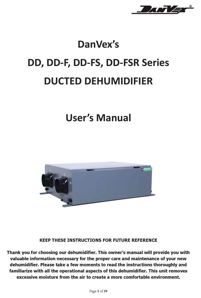
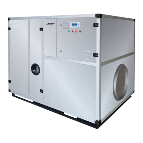
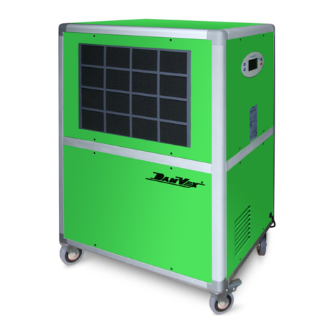
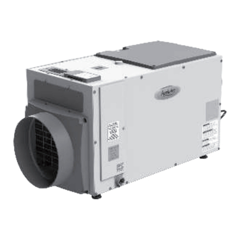
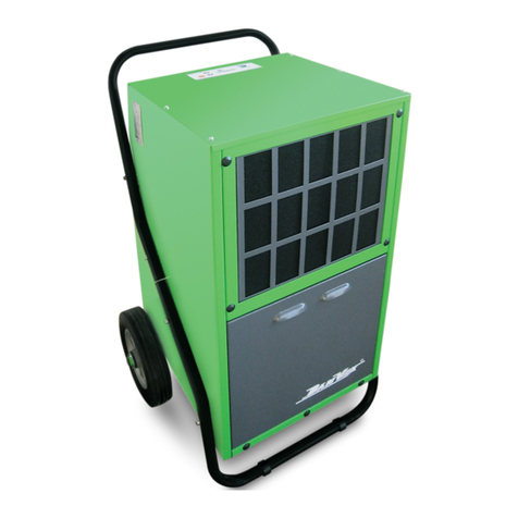
DanVex DEH-1700P User manual

D -EH 1700P
Air dehumidifiers
Operation manual

R
www.danvex.fi
1

R
www.danvex.fi
CONTENT
Air dehumidification...................................................................................................................3
Precautions 7.............................................................................................................................
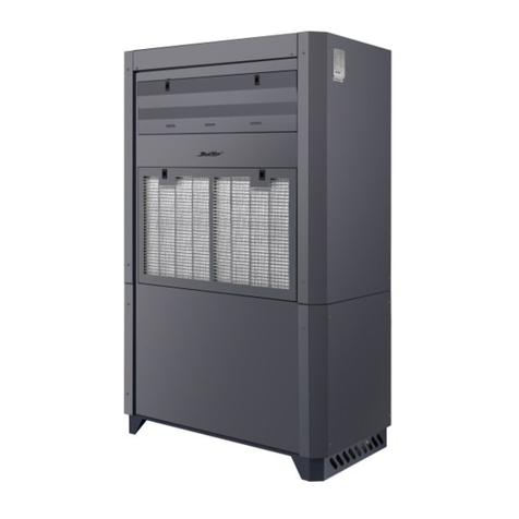
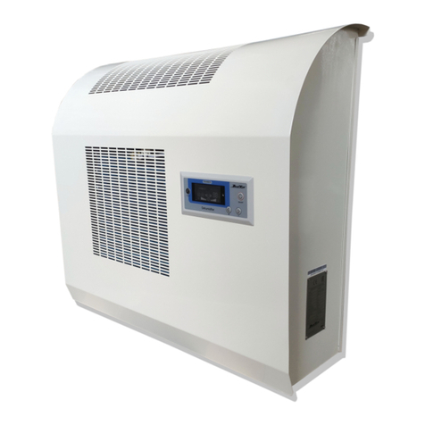
Dehumidifier description 8............................................................................................................
Location and functions 8...............................................................................................................
Dehumidifier design 12.................................................................................................................
Control panel 13...........................................................................................................................
Start up and operation 15.............................................................................................................
Specifications 20..........................................................................................................................
Support and warranty 21..............................................................................................................
2
This instructions manual should always be near
or on the unit!

R
www.danvex.fi
AIR DEHUMIDIFICATION
The moisture from the basin surface (evaporation) is absorbed by the ambient air. Thus, this
increases the air humidity and ultimately results in corrosion, mould, rot, peeling of paint coat-
ings and other unwanted damages.
The below diagram shows an example of metal corrosion rate at different air humidity levels.
3
As you can see the rate of corrosion is insignificant at the relative humidity (RH) below 50%,
and it can be disregarded at RH below 40%. But at the relative humidity above 60% the rate
of corrosion increases considerably. This moisture damage example applies also to many
other materials, such as powders, packaging, wood, electric equipment or electronic devices.
There are two different ways of buildings drying out:
1. By heating with further air exchange:
The ambient air is heated to absorb the moisture and then it is discharged to the atmosphere.
However the total energy output is lost during the moist air discharging to the atmosphere.
020 40 60 80 100
30
60
90
120
0
Air relative humidity, %
Corrosion time

R
www.danvex.fi 4
2. By the air dehumidification:
The moist air in an enclosed room is continuously dehumidified by the condensation
principle. In terms of energy consumption the air dehumidification has one essential
advantage: The energy expenditure requirements are limited by the air volume in the existing
room only. The mechanical heat released during the dehumidification process slightly
increases the air temperature in the room.
When properly used the dehumidifier consumes about 25% of the energy that would be
needed for the „heating and ventilation".
The relative air humidity
The ambient air is a gas mixture that always contains a certain amount of water in the form of
water vapor. This water percentage is expressed in g per kg of dry air (absolute water
content). 1 m3 of dry air weighs about 1,2 kg at 20° C. Depending on the temperature each
kg of the air is only able to absorb a certain amount of water vapor. When this absorptive
capacity is reached the air becomes "saturated" and the relative humidity becomes 100%.
The relative humidity is understood to be the ratio between the water vapor percent currently
contained in the air and the maximum water vapor percent at the same temperature. The
ability of air to absorb water vapor increases with temperature increasing. This means that the
maximum (= absolute) water content increases with temperature increasing.
-5
+10
+15
+20
+25
+30
1,3
3,8
5,1
6,9
9,2
12,9
1,9
5,6
7,7
10,4
13,8
18,2
2,6
7,5
10,2
13,8
18,4
24,3
3,3
9,4
12,8
17,3
23,0
30,3
40% 60% 80% 100%
3
Water vapor content in g/m in the air at the
humidity of
Temp. °C

R
www.danvex.fi
Water vapor condensation
The maximum water vapor volume that can be absorbed increases when the air is heated,
but the water vapor content remains however the same and this results in relative humidity
reduction. In contrast, when the air is cooled, the maximum water vapor volume that can be
absorbed continuously reduces, the water vapor volume contained in the air remains however
the same and the relative humidity increases. If the air temperature falling continues the
capacity to absorb the water vapor volume is reduced until it is equal to the water vapor
content. This temperature is called the dew-point temperature. When the air is cooled below
the dew-point temperature, the water vapor content becomes higher than the maximum
possible water vapor content.
Water vapor displacement starts.
The vapor condenses to water. Thus the moisture is removed from the air. A misted window
glass in winter or a misted bottle with a cold drink are common examples of condensing. The
higher the relative air humidity the higher is the dew-point temperature, and thus it is easier to
fall below the dew-point temperature.
The produced condensate is collected in the unit and discharged.
5
The air flow is cooled on the way through /via the evaporator-condenser till its temperature is
below the dew point. Water vapor condenses, it is collected in a condensate trap and
discharged.

R
www.danvex.fi 6
Heat of condensation
The energy transferred from the condenser to the air consists of: The heat earlier transferred
from the evaporator. Real electrical power. The heat of condensation released through the
condensation of water vapor. When liquid turns into a gaseous state, the energy should flow
in reverse. This energy is called the heat of evaporation. It does not cause any rise of
temperature, it is only necessary for the change from a liquid to a gaseous state. Vice versa,
the energy is released when gas turns into liquid, such energy is called heat of condensation.
The heat generated at condensation and evaporation and is identical. For water this is
2250kJ/kg (4.18kJ = 1kcal). This shows that a relatively large amount of energy is released in
the process of water vapor condensation. If the moisture to be condensed is not generated at
evaporation in the room but is introduced from outside, e.g. via ventilation, the heat of
condensation released in the process will be used for the room heating. If it is required to dry
materials or rooms the heat energy recirculates, i.e. it is consumed during evaporation and is
released during condensation. A large amount of heat energy is generated at the supplied air
dehumidification process, which is expressed as a rise of temperature. Normally the time
necessary for drying does not depend only on the unit capacity, but is determined by the rate
at which the material or the building elements release the moisture they contain.
Evaporator Condenser
Air
temperature
Humidity
time
Air direction

R
www.danvex.fi
SAFETY PRECAUTIONS
1. Read these operations instructions carefully before operating the dehumidifier.
2. Never immerse the unit into water or other liquids.
3. Never use the unit of its cable or power plug is damaged.
4. Electrical devices can be repaired by qualified personnel only, improper repair can be a
source of serious danger for users.
5. Children are not aware of the unit hazard. Never let children operate electric devices if
they are not under proper control.
6. It is required to disconnect the unit from the power supply when it is out-of-operation
and before its cleaning.
7. The unit should be used only with the voltage specified in the table.
8. Please note that this unit is designed for domestic use only. It is intended for household
needs.
9. It is not allowed to put heavy objects on the dehumidifier.
10. Before transportation make sure that the condensate tank is empty to prevent water
leakage.
11. The unit is not intended for use by physically or psychically limited persons (including
children) or by those who have no experience of were not instructed by the persons
responsible for their safety. Children should be under supervision to assure they do not
play with the unit.
12. If the power cord is damaged it should be replaced by the manufacturer, service center
or similar qualified specialists to avoid danger.
13. It is prohibited to use the unit in the locations where chemical substances are used.
14. Before cleaning the unit should be switched off.
7

R
www.danvex.fi 8
DEHUMIDIFIER DESCRIPTION
The unit is designed for automated, versatile and trouble-free air dehumidification. The unit
operates on condensation principle. It is equipped with a closed loop cooling system, low
noise and low maintenance fan and with a power cable with a plug. The unit's control panel is
equipped with an LCD-display used for the system functional checks. A fully automated unit
control system, a trouble-free regulated humidistat, an integrated overflow system as well as
flexible hose connection for direct condensation discharge assure fail safe and long-term
operation of the unit.
The unit complies with the fundamental safety and health requirements of the existing EU
regulations. The unit is easy and safe to operate.
Unit location
The unit is operated in the buildings where dry air is necessary to prevent significant financial
losses (for example, due to mould formation). The unit is mainly used for drying and
dehumidification in saunas and basins. It is also used for dry air maintenance in storage
areas, archives, laboratories, bathrooms, laundries, changing rooms etc.
Functions
The unit operates on condensation principle.
The fan
The fan intakes moist surrounding air into the units front side through the air filter, evaporator
and condenser. The heat is extracted at the cold evaporator. The air is cooled to below the
dew point. The water vapor contained in the room air deposits as condensate or frost on the
evaporator fins. Dried and cooled air is heated in the condenser (radiator) again. Then it is
discharged to outside, the air temperature is about 5 degrees higher than the room
temperature.
The dried air is mixed with surrounding air again.

R
www.danvex.fi
The relative humidity gradually drops to the required RH value due to continuous outside air
circulation through the unit.
Depending on the room temperature and relative humidity the condensed water drips into an
condensate tray (inside the system ) through integrated drain channels. Then the water is
pumped to outside via a drain tube.
Installation
For optimum, economical and safe unit operation the following instructions must be followed:
1. The unit must be installed securely upright to ensure unhindered condensate discharge
through a drain tube.
2. It must be ensured that the air is able to be sucked in freely at the front of the unit and
to be discharged through the top part of the air throttle.
It is prohibited to locate the unit in close proximity to radiators and other heat sources.
9
Dehumidifieed air
Condenser
Compressor
Input drain hole
Evaporator
Moist air

R
www.danvex.fi 10
Important information on electrical connections
Electric wiring of the unit should be done in accordance with DIN VDE 0100, Part 704 for
electric current supply sources equipped with automatic circuit-breakers. If the unit is installed
in humid premises such as saunas or basins it should be equipped with proper automatic
circuit-breakers at the buyer's expense.
Commissioning
Prior to commissioning works or to comply with local requirements it is necessary to check air
intake openings and outlet openings to be sure that they are free from foreign matters. Intake
filters condition should be checked as well.
The following instructions are to be observed:
1. Extension cables should be of proper cross-section.
2. It is allowed to use extension cables if they are fully disentangled or stretched!
3. It is not allowed to pull the unit by the power cord.
4. Upon actuation the unit operates in fully-automatic mode.
5. The unit is equipped with a protection device that prevents the compressor from
switching on at restart immediately after the unit switching off, thus preventing the
compressor damage. The compressor switches on after 3 minutes only.
We do not ensure the efficient operation of the unit if the room temperature is below 6°C and
if the relative humidity is below 40 %.

R
www.danvex.fi
Unit mounting is usually executed along the wall. Humidifier comes standard with mounting
angles to fix the humidifier to the wall as shown at Fig.1 and Fig.2.
11

R
www.danvex.fi 12
DEHUMIFIER DESIGN
1) Dehumidified air outlet
2) Control panel
3) Air filter (inside)
4) Air intake
5) Humidity sensor
6) Temperature sensor
7) Collecting drain pan
8) Valve
9) Compressor

R
www.danvex.fi
13
Control panel
IR receiver
LCD display
Control buttons
Buttons
ON/OFF button
FAN SPEED (high, moderate,
low) control button
Vertical louvers ON/OFF button
Air heating button (option) Timer button
Horizontal louvers ON/OFF button
Humidity control button
Mode selection button (auto,
dehumidification, ventilation, heating opt.)
Display
Auto mode
Ventilation mode
Heating mode
Dehumidification mode
Heating element (option)
Timer indicator
Temperature indicator
Humidity indicator
Timer, temperature, humidity values

R
www.danvex.fi 14
IR transmitter
Mode selection button
Status LCD display
Ventilation modes
Cancel button
Louvers ON/OFF button
Humidity control
button
ON/OFF button
Timer off button
Timer on button
Confirmation button
Heating button
(option)

R
www.danvex.fi
15
Startup and operation
Mode selection (1)
To set the necessary mode press the “MODE” button
Auto > Dehumidification > Ventilation > Heating
Attention:
- Heating mode is available only at the models
equipped with the heating element.
Air flow selection (2)
Press the “FAN” button to set the air flow.
Each pressing changes the fan speed.
Auto > Low > Moderate > High
Attention:
- In “Auto FAN” mode the dehumidifier selects the
optimum speed depending on the room temperature.
- In “Dehumidification” mode the fan speed button
is not active.
Temperature setting (3)
Press Up or Down buttons to select the necessar
temperature from + 16C to 31C.
Dehumidifier startup (4)
Press “ON/OF” button and the panel will send the
set information. The dehumidifier will start working
after two audio signals.
Attention:
- In case of the repeated startup you can skip the
steps 1 – 3 if the fan and temperature parameters
are not to be changed.
- In case of the repeated switching on the
compressor will start not earlier than in 3 minutes
after the humidifier switching off.

R
www.danvex.fi 16
(1) Select the Auto mode by pressing the “MODE” button.
(2) Set the necessary level of the fan.
(3) Press “ON/OFF” button to start the dehumidifier in the
Auto mode.
Attention:
In the auto mode the dehumidifier sets the Dehumidification
mode, Heating mode by itself depending in the room
temperature and humidity according to the table:
Auto mode
In Auto mode the dehumidifier works only if it's equipped with the optional heater
(heating element).
Mode/Temperature
o o
<23 С or >28
humidity >80%
o o
23 С ~28 С
o o
<23 С or >28 С
humidity <80%
Dehumidification
Heating
Operating
Operating
Not operating
Not operating
Not operating
Operating

R
www.danvex.fi
17
Louvers
Horizontal louvers
Horizontal air flow Downward air flowVertical air flow
Attention:
- Louvers can be fixed in the required direction. Use the “SWING” button on the
dehumidifier panel to turn it on/off.
- To provide the better effect it's recommended to install the shutters horizontally
or vertically in the dehumidification mode and downwards in the heating mode.
Vertical louvers
Attention: don't try to regulate the
air flow louvers manually

R
www.danvex.fi 18
Wiring diagram

R
www.danvex.fi
19
1) Upper trim panel
2) Lower trim panel
3) Control panel
4) Rear housing panel
5) Left housing panel
б) Upper housing panel
7) Condenser
8) Mounting angle
9) Electric heating element (option)
10) Right housing panel
11) Крыльчатка вентилятора
12) Cover
13) Fan impeller
14) Motor fixation panel
15) Fan case
16) Evaporator
17) Condensate collecting pan 1
18) Condensate collecting pan 2
19) Lower trim panel
20) Mounting low panel
21) Compressor
22) Valve
23) Automatic drain system
24) Drain tube
25) Transport wheel
26) Transport wheel
27) Condenser
28) Contact bank
29) Motor condenser
30) Controller PCB
31) Transformer
32) Dehumidifier controller
33) Sensor
34) Mounting stop angle
35) Filling nipple
36) Humidity sensor
37) Temperature sensor
38) Electric wire
Other DanVex Dehumidifier manuals

DanVex
DanVex DEH-1700wp User manual

DanVex
DanVex DD Series User manual

DanVex
DanVex DEH-3K User manual

DanVex
DanVex DEH-1200P User manual

DanVex
DanVex AD-200 User manual

DanVex
DanVex DEH-290h User manual

DanVex
DanVex AD-550 User manual

DanVex
DanVex DEH-600P User manual

DanVex
DanVex AD-200 User manual

DanVex
DanVex DEH-900i User manual