Datecs LP-50H User manual

1 DATECS
Service Manual
LINE THERMAL PRINTER
MODEL LP/EP-50H

THE INFORMATION IN THIS DOCUMENT CANNOT BE REPRODUCED IN ANY MECHANICAL, ELECTRICAL
OR ELECTRONIC WAY AND UNDER ANY CIRCUMSTANCES WITHOUT THE WRITTEN CONSENT FROM DATECS LTD.
VERSION 01 / 2004

CONTENTS
INTRODUCTION ..................................................................................................... 5
1. FEATURES ................................................................................................. 5
2. SPECIFICATIONS ....................................................................................... 6
3. DISASSEMBLY AND REASSEMBLY ......................................................... 7
3.1 Disassembly Procedure .............................................................................. 7
3.2 Reassembly Procedure ............................................................................. 11
4. SERVICE PARTS LIST ............................................................................. 12
4.1 Parts List for Mechanism .......................................................................... 12
4.2 Disassemble Drawing................................................................................ 13
5. BLOCK SCHEME ..................................................................................... 14
6. MAIN BOARD ........................................................................................... 15
6.1. Electrical Diagram ..................................................................................... 16
6.2. PCB .......................................................................................................... 17
Top View ................................................................................................... 17
Bottom View ............................................................................................. 18
Top Layer .................................................................................................. 19
Bottom Layer ........................................................................................... 20
6.3. List of parts ............................................................................................... 21
7. INTERFACE .............................................................................................. 24
7.1. Parallel ..................................................................................................... 25
7.1.1 Electrical Diagram ..................................................................................... 25
7.1.2. PCB .......................................................................................................... 26
Top View ................................................................................................... 26
Bottom View ............................................................................................. 27
Top Layer .................................................................................................. 28
Bottom Layer ............................................................................................ 29
7.1.3. List of parts ............................................................................................... 30
7.2. RS232 ....................................................................................................... 31
7.2.1 Electrical Diagram ..................................................................................... 32
7.2.2. PCB .......................................................................................................... 33
Top View ................................................................................................... 33
Bottom View ............................................................................................. 34
Top Layer .................................................................................................. 35
Bottom Layer ............................................................................................ 36
7.2.3. List of parts ............................................................................................... 37
8. OUTLINE DRAWING ................................................................................. 38
9. WALL MOUN UN UNTING HOLES LAYOUT DRAWING ........................... 39

4
1 DATECS LP/EP-50H
1 DATECS
Contact Information
Headquarters: DATECS Ltd.
Bulgaria, 1784 Sofia
115A Tzarigradsko shosse
tel.: +359 2 8165 500, +359 2 8165 501, +359 2 8165 506
fax: +359 2 8165 510
www.datecs.bg
e-mail: [email protected]

5
Service Manual
INTRODUCTION
This manual describes the disassembly, reassembly, and maintenance procedures of the line
thermal printer LP-50H.
1. FEATURES
This small line thermal printer is designed for various types of data communication terminals
and measuring instrument terminals. Its abundant built-in features allow you to widely use
this printer for different applications. Prior to using it, read and understand this manual
thoroughly.
ySmall, lightweight, and installable in a narrow area
yHigh speed and low noise, owing to line thermal print
yLong-life printing head and high reliability, owing to the simple mechanism
yEasy paper-loading, owing to the auto-loading function
yBuilt-in input buffer
yCapable of printing a bar code (Special command)
yCapable of accommodating both thermal paper and label paper
yA little discharge (1 sheet) of the label paper at power-on or paper replacement
yCapable of printing in two colors (when special paper is used)
yExternal characters registration function (94 kanji characters, 95 ANK characters)

6
1 DATECS LP/EP-50H
2. SPECIFICATIONS
LP- 50H EP-50H
Printing system Line thermal dot printing
Printing width 48 mm (384 dots/line)
Dot density 8 dots/mm (Width, Length)
Paper feed pitch 0.125 mm
Printing speed up to 50 mm/s
Character size 12×29 Bold, 8×12, 10×16, 12×20, 14×24, 12×24, 9×16,
32×48, 24×24 (only for asian versions) 24×24 (only for asian versions)
Character types Alphanumerals, symbols, international Alphanumerals, symbols, international
characters (Choose from 13 countries) haracters (Choose from 20 countries)
Bar code type UPC-A/E, JAN(EAN) 13-/8-column, ITF, UPC-A/E, JAN(EAN) 13-/8-
CODE 39, CODE 128, CODABAR, EAN128, column, ITF, CODE 39, CODE 128,
Plessey, PDF417 CODABAR, PDF417
Paper Thermal paper roll : 58 + 0/- 1 mm xf83 (max.) mm, 60~75mm thick
Thermal label paper : 58 + 0/- 1 mm x f83 (max.), 150mm thick (max.)
(L and M Spec. only) Label width: 56 mm (max.)
Label length: 25 mm/sh. (min.)
Interface Serial (RS-232C), Parallel (CENTRONICS compliant)
Input buffer 4 KB 16 KB
Download characters Up to 26 loaded characters To downloaded fonts: 12×24, 9×16
Label detecting function Capable of selecting label interval detection no
AC adapter Rated input : 100~240 V, 50/60 Hz, 40 VA
Rated output : 12 V DC, 2,5 A
Power consumption At non-printing: Approx. 2 W
At printing: Approx. 15 W (approx. 20 W at maximum)
Weight Main body: Approx. 600 g (Paper roll excluded)
AC adapter: Approx. 350 g
Outer dimensions 106 (W) ´ 184 (D) ´ 110 (H) mm
Operating temperature and 5~40 °C, 35~85 % RH (No dew condensation)
humidity
Storage temperature and -20~60°C, 10~90% RH (No dew condensation)
humidity
Reliability Printing head life: (25°C)
Pulse resistance : 50 million pulses or more (Print rate 12.5%)
Wear resistance : 50 km or more (With recommended thermal paper at
normal temperature and humidity)

7
Service Manual
3. DISASSEMBLY AND REASSEMBLY
In case of maintenance work, observe the following:
CAUTION
yIf the printer functions properly, do not disassemble, reassemble, or adjust it. Particularly, do not loosen
each setscrew unless required.
yAfter inspecting the printer, be sure to confirm that it is free from error.
yNever try to print without setting the printing paper in the printer. Confirm that it is properly set.
yIn case of maintenance work, be careful not to leave the used parts or screws in the printer.
yWhen handling the thermal head or control board, do not wear the gloves which will easily cause static
electricity. Prior to handling it, discharge static electricity from your body.
Also, never conduct maintenance work in a place where the printer will be easily electrified.
yWhen disassembling and reassembling, check the cords and boards for any damage, and do
not cable or fix them in an inappropriate manner by force.
yNever carry out maintenance work with the power turned on.
3.1 Disassembly Procedure
1. Prior to Disassembly
yDisconnect all the cables from the rear of the main body. For your safety, unplug a power cord from a plug
socket.
yLeave the printer cover attached.
8
1 DATECS LP/EP-50H
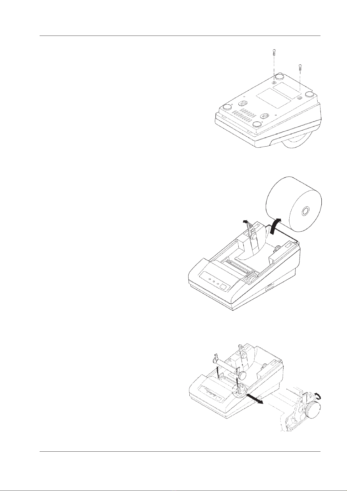
2. Removing the Screws from the Bottom of the Main Body
yTurn over the printer body.
yRemove two M3 × 10 (BT) screws.
Then, turn back the printer body to its
original position.
Do this, holding its upper and bottom covers.
3. Detaching the Printer Cover and Paper Roll
yDetach the printer cover. Put a finger, etc.
on a convexed part from the rear of the printer
body and lift.
yDetach the paper roll. If the paper roll has been set
in the printer, cut he surplus paper and detach
it gently.
See “HOW TO REMOVE REMAINING PAPER
ROLL” in the USER’S MANUAL.
4. Detaching the Platen Roller Unit
yRaise the head-up lever.
yUnlock the platen roller unit. Pull up the blue
levers on both sides of the platen roller unit,
while opening them outside.
yDetach the platen roller unit. Hold the blue levers
on both sides of pull up. Keep the platen
unit carefully so as not to damage it.
yLower the head-up lever.

9
Service Manual
5. Detaching the Upper Cover
yLift the upper cover from the rear of
the printer body. When this is done,
lift it gently.
yDisconnect all the connectors. Holding up
the upper cover, disconnect all the connectors
rom the control board. Hold the base of the
connector to disconnect it. Pulling the cable will
ap it.
yDisconnect the FG cable. Remove one
M3 × 8 (BT) screw used to secure it to the
control board.
yDetach the upper cover.
6. Detaching the NPE Sensor Unit
yRemove one M3 ×10 (BT) screw used
to secure the NPE sensor unit.
yPull out a cable.
7. Detaching the Operation Panel Board
yRemove two M2.6 × 8 (BT) screws. Turn over
the upper cover and unscrew the operation
panel board.
yDetach the operation panel board.
10
1 DATECS LP/EP-50H
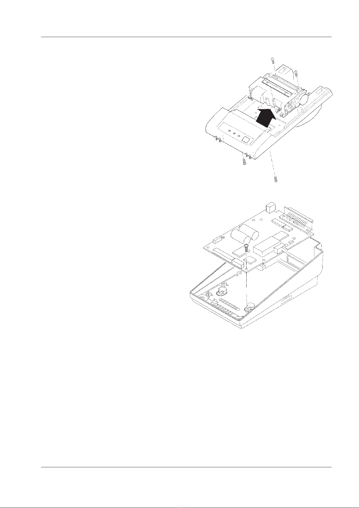
8. Detaching the Printer Mechanism
yRemove four M2.6 × 8 (BT) screws used to
secure the printer mechanism. Remove
two screws each from the front and back.
yPull out the printer mechanism. Pull it out
gently to the paper holder side (front) without
pulling a cable.
If the label sensor is attached, separate it from
the printer mechanism.
9. Detaching the Control Board
yRemove one M3 ×8 (BT) screw.
yTurn on the Power switch.
yDetach the board. Slightly opening outside
the plastic part near the Power switch,
slide it upward to the near side of the
printer body to detach.
10. Detaching the shielding plate.
* For Steps 5 to 9, carry out only those required for maintenance.
This manual suits for next models
1
Table of contents
Other Datecs Printer manuals

Datecs
Datecs PP-55 User manual

Datecs
Datecs EP-60 User manual

Datecs
Datecs WPP-250 Quick start guide

Datecs
Datecs FP-2000 User manual

Datecs
Datecs EP-2000 User manual

Datecs
Datecs DPP-350 User manual

Datecs
Datecs PP-60 User manual

Datecs
Datecs DPP-250 User manual

Datecs
Datecs DPP-255 User manual

Datecs
Datecs EP-60 Operating and maintenance manual


