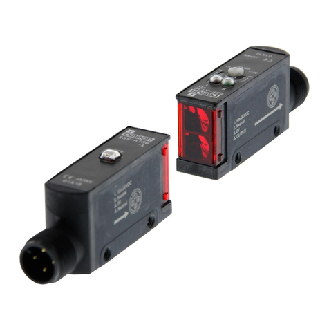
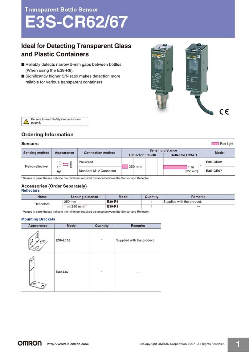
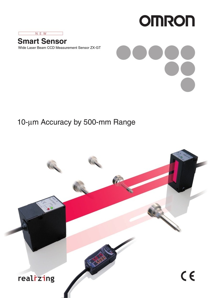
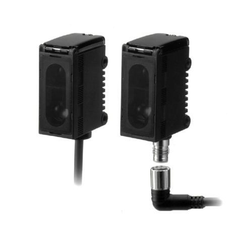
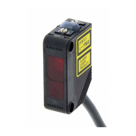
Omron E3AS-HL500MT 2M User manual

Lasersafetymeasuresforlaserequipmentarestipulatedbythecountryofuse.Follow
theinstructionsdescribedbelowcategorizedinfourcases.
・UsageinJapan
TheJISC6802:2014standardstipulatesthesafetyprecautionsthatusersmusttake
accordingtotheclassofthelaserproduct.Thisproductisclassifiedintoclass1defined
bythisstandard.
・UsageinU.S.
ThisproductissubjectedtotheU.S.FDA(FoodandDrugAdministration)laser
regulations.ThisproductisclassifiedintoClass1bytheIEC60825-1:2014standard
accordingtotheregulationsofLaserNoticeNo.56oftheFDAstandard.Thisproductis
alreadyreportedtoCDRH(CenterforDevicesandRadiologicalHealth).
AccessionNumber:1920014-001
WhenusingadeviceequippedwiththeproductintheU.S.,attachanFDAcertification
labelnearthesensormountedoncustomerequipment.
CMOSLaserSensor
ThankyouforselectingOMRONproduct.Thissheetprimarilydescribesprecautions
requiredininstallingandoperatingtheproduct.
Beforeoperatingtheproduct,readthesheetthoroughlytoacquiresufficient
knowledgeoftheproduct.Foryourconvenience,keepthesheetatyourdisposal.
PrecautionsforCorrectUse
Packagecontents
PrecautionsforSafeUse
Pleaseobservethefollowingprecautionsforsafeuseoftheproducts.
•DonotreverseconnectionofDCpowersupplypolarity.Donotconnect
toACpowersupply.
•Donotshort-circuittheload.
•NeverusethisproductwithACpowersupply.Otherwiseitmay
explode.
•Themaximumpowersupplyvoltageis30VDC.Beforeturningonthe
product'spower,makesurethatthesupplyvoltagedoesnotexceed
themaximumpowersupplyvoltage.
•Donotusetheproductinenvironmentswhereflammableorexplosive
gasesarepresent.
•Pleaseassessthesafetybeforehandwhenusingtheproductin
chemicalsand/oroilenvironments.
•Donotremodeltheproduct.
•Donottouchthemetalsurfacewithyourbarehandswhenthe
temperatureislow.Touchingthesurfacemayresultinacoldburn.
•Burninjurymayoccur.Theproductsurfacetemperaturerises
dependingonapplicationconditions,suchastheambienttemperature
andthepowersupplyvoltage.Attentionmustbepaidduring
operationorcleaning.
•Donothittheproductusingahammerforinstallation.
•Theproductmustbeinstalledwiththespecifiedtorqueorless.
ForM8connectorandPre-wiredM8connector,thepropertightening
torqueisfrom0.3to0.4N・m.
IncaseofM12Pre-wiredsmartclickconnector,manuallytightenthe
connector.
•Tighteningtorqueforthemountingholeis0.6N・morless(M3screw).
•Donotusetheproductinambientatmosphereorenvironmentexceeding
therating.
•Outputpulsesmaybegeneratedwhenthepoweristurnedoff.Itis
recommendedtoturnoffthepoweroftheloadorloadlinefirst.
•TheextensionofthecordunderthestandardI/Omodeshouldbe100m
orless.UndertheIO-Linkmode,thelengthshouldbe20morless.
•Donotpullthecordtoostrongly.
•Besuretoturnoffthepowersupplywhenconnectingordisconnecting
thecable.
•Waitforatleast600msafterturningontheproduct'spower.
•TheproductisratedasIP67butpleaseavoidusingtheproduct
underwater,underrain,andoutdoors.
•IftheSensorwiringisplacedinthesameconduitsorductsashigh-voltage
orhigh-powerlines,inductivenoisemaycausemalfunctionordamage.
Wirethecablesseparatelyoruseashieldedcable.
•Donotusetheproductindirectsunlight.
•Donotusetheproductwherehumidityishighanddewcondensation
mayoccur.
•Donotusetheproductwherecorrosivegasesmayexist.
•Useakeylocktopreventmalfunctionifhigh-pressurewashwaterorother
substancescomeintocontactwiththebutton.
•Donotapplyhigh-pressurewashingwaterdirectlytothesensor'slight
emitting/receivingsurfacefromashortdistance.Astheantifouling
featuremaybeimpaired,keepasufficientdistancefromthelightemitting
/receivingsurface.
•Donotusetheproductatalocationsubjecttoshockorvibration.
•Touseacommerciallyavailableswitchingregulator,FG(frameground)
mustbegrounded.
•Thisproductcannotbeusedasadetectiondeviceforhumanbody
protection.
•Donotuseorganicsolvents(e.g.paintthinnerandalcohol)forcleaning.
Otherwiseopticalpropertiesandprotectivestructuremaydeteriorate.
•Besuretochecktheinfluencecausedbysurroundingenvironmentssuch
asbackgroundobjectsand/orLEDlightingbeforeusingtheproduct.
•Donotexceed100,000writingoperationsoftheEEPROM(non-volatile
memory).SettinginformationiswrittentotheEEPROMwhenathreshold
valuechange,teaching,orzeroresetisexecuted.
Instructionsheet(thissheet),Compliancesheet,Indexlist(attachedfor
IO-Linktypeonly),FDAcertificationlabel,Warninglabel
INSTRUCTIONSHEET
Disposeinaccordancewithapplicableregulations.
Indicatesapotentiallyhazardoussituationwhich,ifnotavoided,
willresultinminorormoderateinjury,ormayresultinseriousinjury
ordeath.Additionallytheremaybesignificantpropertydamage.
Thisproductisnotdesignedorratedforensuringsafetyofpersons
eitherdirectlyorindirectly.Donotuseitforsuchpurpose.
WARNING
Donotusetheproductwithvoltageinexcessoftheratedvoltage.
Excessvoltagemayresultinmalfunctionorfire.
Indicatesapotentiallyhazardoussituationwhich,ifnotavoided,
mayresultinminorormoderateinjuryorinpropertydamage.
CAUTION
●MeaningofSignalWords
PRECAUTIONSONSAFETY
Tosafelyuselaserproducts
Itscomponentmaybedamagedand/ordegreeofprotectionmaybedegraded.
Pleasedonotapplyhighpressurewaterintensivelyatoneplaceduringcleaning.
WARNING
WARNING
CAUTION
FDAcertificationlabel
©OMRONCorporation
2020
AllRightsReserved.
E3AS-HL150□/HL500□
ThefollowingnoticeappliesonlytoproductsthatcarrytheCEmark.
Notice:
Inaresidentialenvironment,thisproductmaycauseradiointerference,
inwhichcasetheusermayberequiredtotakeadequatemeasures.
LookingintotheOutgoinglightcontinuouslymaycausevisualimpairment.
DonotlookdirectlyintotheOutgoinglight.
Caution-Useofcontrolsoradjustmentsorperformanceofproceduresother
thanthosespecifiedhereinmayresultinhazardousradiationexposure
Attention-Lʼutilisationdescommandesouréglagesoulʼexécutiondes
procéduresautresquecellesspécifiéesdanslesprésentesexigences
peuventétrelacausedʼuneexpositionàunrayonnementdangereux
Donotdisassemblethisproduct.Doingsomaycauseexposureto
thebuilt-inlightsourcewhichcandamageeyesandskin.Never
disassembleit.
Manufacturer:
OmronCorporation,
ShiokojiHorikawa,Shimogyo-ku,
Kyoto600-8530JAPAN
TRACEABILITYINFORMATION:
ImporterinEU:
OmronEuropeB.V.
Wegalaan67-69
NL-2132JDHoofddorp,
TheNetherlands
Centeroflaserprojection
Warninglabel
Model
1
・UsageinChina
ThisproductisclassifiedintoClass2bytheGB7247.1:2012(IEC60825-1:2007)standard.
WhenusingadeviceequippedwiththeproductinChina,attachaWarninglabelnear
thesensormountedoncustomerequipment.
・UsageincountriesotherthanU.S.andChina
ThisproductisclassifiedintoClass1bytheIEC60825-1:2014/EN60825-1:2014+A11:2021
standard.
*5630539-9D*
Installation
Donottouchtheemitterand/orreceiverblockofthesensor.Fingerprint
depositsmayresultinimproperdetection.Ifaccidentallytouched,
pleasewipegentlywithadrycloth.Donotuseorganicsolvent(e.g.
paintthinnerandalcohol).
1
MountingoftheSensor
1-1
Mountingbracketsaresoldseparately.
Tighteningtorqueforthemountingholeis0.6N・morless(M3screw).
<Sizeofinstallationholes(Unit:mm)>
ConstraintsonSensorInstallation
1-2 ConnectionMethod
2-2
CordAllowableBendingRadius
2-3
■Orientationconsiderationsforinstallation
Connection
2
Input/OutputCircuitDiagram
2-1
Totalloadcurrentofthetwooutputroutesmustbe100mAorless.
(Detectionclosetoawall) <Detectioninahole>
<Detectingaworkpiecewithastep>
Stabledetectionis
availableevenforthe
leveldifferencepart.
Abnormaldetection
valuemayappearatthe
leveldifferencepart.
Detectionisnot
possibleiftheemitter
and/orreceiveris
blocked.
■UsingPin2(whitewire)asexternalinput"3-3ExternalInput"(page3).
①
④
②
③
+V
OUT1
OUT2
0V
Brown
Black
White
Blue
Brown
Black
White
Blue
Brown
Black
White
Blue
Brown
Black
White
Blue
Brown
Black
White
Blue
Load
NPN
Model
Outputmethod
Input/Outputcircuitdiagram
E3AS-
□□N□
10to30VDC
10to30VDC
10to30VDC
10to30VDC
①
④
②
③
+V
OUT1
OUT2
0V
PNP/COM□
StandardI/O
Mode
①
④
②
③
①
④
②
③
+V
C/Q
DO
0V
+V
C/Q
DI/DO
0V
IO-LinkMaster
PNP/COM□
IO-LinkMode
E3AS-
□□D□
or
E3AS-
□□T□
Load
Load Load
NPN
Model Method Input/Outputcircuitdiagram
E3AS-
□□N□
PNP/COM□
StandardI/O
Mode
PNP/COM□
IO-LinkMode
E3AS-
□□D□
or
E3AS-
□□T□
TheextensionofthecordunderthestandardI/Omodeshouldbe100mor
less.TheextensionofthecordintheIO-Linkmodeshouldbe20morless.
Pre-wiredModels
M12SmartclickConnectorModel
M8ConnectorModel
E3AS-HL□□ □M
E3AS-HL□□M3
M8ConnectorModels
E3AS-HL□□-M1TJ
E3AS-HL□□-M3J
Brown
Black
White
Blue
BendingforPre-wiredandConnectorModels
Cablespec.
PVCcable
BendingofsensorI/Oconnectorcord
Model
XS3F-M8PVC
XS2F/W-D4-F
XS5F/W-D4-F
XS5F/W-D4-X
XS5F/W-D4-XR
External
diameter
Φ4
External
diameter
Φ5
Φ6
Φ6
Φ6
Φ6
Cable
Materialspec.
PVC
Incombustiblerobot
Incombustiblerobot
Highlyoil-resistantPVC
Highlyoil-resistantrobotPVC
Lengthnotallowed
tobend:mm
5
Lengthnotallowed
tobend:mm
0
0
0
0
0
Minimumbending
radius:mm
13
Minimumbending
radius:mm
36
40
40
40
40
Reference
surface
Referencesurface
2-M3×P0.5
Throughhole
25.4
45.5
7.7
3
28.7
■UsingPin2(whitewire)asoutput
Note1.ThestandardI/OmodeisusedasPNPON/OFFoutput.
Note2.TheIO-LinkmodeisusedforcommunicationswiththeIO-Linkmaster.
TheC/QisusedforIO-Linkcommunications.ThesensoroutputDOis
usedforON/OFFoutput.
Note3.Fordetailedinformationonmodels,ratings,andperformance,referto
"8RatingsandSpecifications"(page12).
Externalinput NPN PNP
ONtime
OFFtime
①
④
②
③
+V
OUT1
EXTIN
0V
Load
①
④
②
③
+V
OUT1
EXTIN
0V
Load
100mAorless
100mAorless
ExternalInput
ExternalInput
0Vshort-circuitor1.5Vorless
Powersupplyvoltage
short-circuitoropen
Powersupplyvoltageshort-circuitor
withinpowersupplyvoltage-1.5V
0Vshort-circuitoropen
(AWG24,insulatorΦ1.05)
Lengthnot
allowedtobend:
5mm
Minimumbendingradius
R13mm
Lengthnotallowedtobend
Minimumbendingradius
2
Lesssusceptible
tostraylight.
Susceptibletostraylight,
andthedetectedvalue
mayvary.

Externalinputcanbeselectedfromthemenusettingscreen.
ExternalInputin"6DetailedSettings"( page8)
Theexternalinputof"Output2Function"cannotbeusedinIO-Linkmode.
Variousteachingcanbeexecutedwithinasmuchtimeasspentfor
buttonoperations.
"4Teaching"( page5to6).
Thedetectedvaluewhenzeroresetisexecutedissetto"0."
ExternalInput
3-3
OUTindicator
Displaysoutputstate
ofoutput1(Pin4,blackwire).
Zeroresetindicator
TurnedONwhenthezeroreset
functionisenabled.
■LaseOFF
■Teaching
■ZeroReset
●Zeroresetcancel
●Zeroresetexecution
■Otherbuttonoperations
■Howtoswitchtoeachscreen
Teachingexecution
Zeroresetexecution
Zeroresetcancel
Keylockexecution/cancel
"4Teaching"
( page5)
"5-1KeyLock"
( page7)
"5-3ZeroReset"
( page7)
Menusettingscreen
"6DetailedSettings"( pages8to9)
Mainscreen
Pressandhold
forover3s
Pressforless
than1s
or
Thresholdvaluesettingscreen
"4-4ThresholdValueManual
Operations"( page7)
Operation
Simultaneously
forover3s.
Simultaneously
forover3s.
Simultaneously
forover3s.
+
+
+ +
Reference
UP
UP
UP
DOWN
DOWN
DOWN
DOWN
TEACH
T
TEACH
T
TEACH
T
TEACH
T
Input ExternalinputON
ON<15ms
ExternalinputOFF
ExternalinputOFF
Emission EmissionOFF
ON
OFF
ON
OFF
Laser
OFF<25ms
Input External
inputON
External
inputON
25ms<ON<3s
ExternalinputOFF
ExternalinputOFF
ExternalinputOFF
ExternalinputOFF
Outputbeforezeroresetexecution
Outputafterzeroresetexecution
Outputbeforezeroresetexecution
Outputafterzeroresetexecution
ON
OFF
Output1
Input
Output1
Sensorresponsetime
Sensorresponsetime
3s≦ON
ON
OFF
Settings
3
Operation/DisplayLookupTable
3-1
■Nameandfunctionofeachpart
■Mainscreen
Thresholdvalueindicator
Displaysthesetvalueofthethreshold
valuein[mm]*1.
Detectedvalue
Displaysthecurrentdetectedvaluein[mm]*1.
[TEACH]button
・Executesvarious
teaching.
[UP]button
・Changesthe
thresholdvalueorset
value.
[DOWN]button
・Changesthe
thresholdvalueorset
value.
・Toswitchbetween
themainscreenand
menusettingscreen,
pressandholdthis
buttonforover3s.
T
Indicator'sroleisdifferent
dependingonthesensorstate.
OUTindicator
Displaysinput/outputstateofoutput2
(Pin2,whitewire).
Power&Communication
indicator(green)
Operationindicator
(orange)
MODE
3sec
MODE
3sec
Thefunctionassignedtooutput2(Pin2,whitewire)canbeselected.
Theoutput2fanctioncanbeselectedfromthemenusettingsection.
Output2functionin”6DetailedSettings”( page8)
*1.Output2turnsONwhenasystemerrororloadshortcircuiterror
occurs.
Output2Function
3-2
Menudisplay
Out1Invert
Out2Single
Input
Error
Function
Output1Invert
Output2[Single]
ExternalInput
ErrorOutput*1
LaseremissionisturnedOFF.Whenthelaseremissionisstopped,the
intensityisinsufficient.
Output1 Output2
OFFtime ONtimeOFFtime ONtime
ExternalInput
3
ErrorOutput
Normal Inputting
Setting
*1.Referencevalue
MODE
3sec
Screendisplay
Item
Timeelapseswithoutoperation

Themodeofoutput1(Pin4,blackwire)canbeselected.
Anoutputmodecanbeselectedfromthemenusettingscreen.OutputModein"6DetailedSettings"( page8)
Outputmodeisselectedautomaticallybyexecutingeachteaching."4Teaching"( page5to6)
*1.BGSoperation:Whenintensityisnotsufficientanddistanceisoutofrange,ifN.O.orN.C.isset,outputisOFForON,respectively.
FGSoperation:Whenintensityisnotsufficientanddistanceisoutofrange,ifN.O.orN.C.isset,outputisONorOFF,respectively.
*2.Enabledonlyifbackgroundreferenceteaching(sensitive)isexecuted.So,itisnotpossibletoselectthe"Distance+Intensity"modefromthemenusettingscreen.
DifferencebetweenBGSandFGS
BGS:Influencefromthebackgroundiscontrolled.BGSissuitablefordetectionwhenthereisnobackgroundorwhentheobjectisfarfromthebackground.
BGSisusableirrespectiveofthepresenceofbackground.
FGS:Influencefromtheclose-rangeviewiscontrolled.FGSissuitablefordetectionwhenthebackgroundisclosetotheobjectorwhentheobjecthasa
mirror-surface,leveldifference,orlowlyreflectiveobject.FGSisnotusablewithoutabackgroundbecausethebackgroundisalwaysdetected.
OutputMode
3-4
■SinglePointMode[Single]
■WindowBGSmode[WindowBGS]
■WindowFGSmode[WindowFGS]
■SinglePointMode[Single]
■WindowBGSmode[WindowBGS]
■WindowFGSmode[WindowFGS]
Note1.Shownabovearetheproductoperationoffactorysettings.For
theinitialfactorysettings,referto"6DetailedSettings"page9.
DisplaySpecification
3-5
SinglePoint
[Single]
WindowBGS
[WindowBGS]
WindowFGS
[WindowFGS]
Distance+Intensity*2
[Dist+Int]
Sensingmethod
*1
BGS
FGS
2-point/Backgroundteaching
Backgroundteaching
Objectteaching
Backgroundreference
teaching(normal)
Backgroundreference
teaching(sensitive)
"4-1BasicTeaching"( page5)
"4-2AdvancedTeaching"( page6)
"6-11ABTFunction"( page11)
"4-2AdvancedTeaching"
( page6)
"4-1BasicTeaching"
( page5)
Threshold
Ratedsensingdistancerange
Standard
I/O
Mode
ON
OFF
ON
OFF
ON
OFF
ON
OFF
IO-Link
Mode
Near
Far
ON
ON
OFF
Near-side
threshold
Far-side
threshold
Ratedsensingdistancerange
Near-side
threshold
Far-side
threshold
Ratedsensingdistancerange
OFF
OFF
ON
Near-sidethreshold
(SP2)
Far-sidethreshold
(SP1)
Near-sidethreshold
(SP2)
Far-sidethreshold
(SP1)
Near
Far
OFF
OFF
ON
ON
ON
OFF
Thresholdvalue
(SP1)
N.C.settingN.O.setting
Near
Far
ON
OFF
OFF
ON
Power/Communication
indicator(green)
Power/Communication
indicator(green)
Power/Communication
indicator(green)
Power/Communication
indicator(green)
Power/Communication
indicator(green)
OperationIndicator(orange)
Output1
Output2
Power/Communication
indicator(green)
OperationIndicator(orange)
CommunicationOutput
Output2
Flashing
(1secondcycle)
ON
OFF
1
0
ON
OFF
Standard
I/O
Mode
ON
OFF
ON
OFF
ON
OFF
ON
OFF
IO-Link
Mode
OperationIndicator(orange)
Output1
Output2
OperationIndicator(orange)
CommunicationOutput
Output2
Flashing
(1secondcycle)
ON
OFF
1
0
ON
OFF
Standard
I/O
Mode
ON
OFF
ON
OFF
ON
OFF
ON
OFF
IO-Link
Mode
OperationIndicator(orange)
Output1
Output2
OperationIndicator(orange)
CommunicationOutput
Output2
Flashing
(1secondcycle)
ON
OFF
1
0
ON
OFF
4
Outputmode Function
Description Relationswithteaching Reference
Theoutputisinvertedwhenthedetectedvaluefalls
belowthethresholdvalue(SP1).
Theoutputisinvertedwhenthecoincidencebetweenthe
distanceandintensityislessthanthethresholdvalue.
Theoutputisinvertedwhenthedetectedvalueis
betweentheFarside(SP1)andNearside(SP2)
thresholdvalues.

Near-sidethresholdvalue
Far-sidethresholdvalue
Margin Background(referencesurface)
OFF
ON
ON
Margin
Teaching
4
・Foroutput1(Pin4,blackwire),5typesofteachingareusablebybutton
operations.
・Foroutput2(Pin2,whitewire),teachingisnotusablebybuttonoperations.
However,output2teachingcanbeexecutedbythecommunication
commandsofIO-Link(only2-pointteachingandbackgroundteachingis
usable).
■Teachingoperationlookuptable
TEACH
TTEACH
T
Item
2-pointteaching
PressQuickly
PressQuickly
PressQuickly
TEACH
TTEACH
T
Operation
TEACH
T
Item
*1.Thisisthefactorysetting.
Whenpressingquickly,itmustlongerthan25msandshorterthan1s.
Whenpressingandholding,itmustshorterthan5s.
TeachingSelection[Teach3sec]
[Background]*1
[Object]
Backgroundteaching
Objectteaching
Press&Hold
Press&Hold
Operation
Item
Bg.Ref.TeachingSelection
[Ref.Teach]
[Normal]*1
[Sensitive]
Bg.referenceteaching(normal)
Bg.referenceteaching(sensitive)
Operation
■2-pointTeaching
BasicTeaching
4-1
Thisisthebasicsetting.
1. Pressthebuttonquicklywithoutanyobjects(longerthan25msandshorterthan1s).
・Thethresholdvalueissetatadistancebetweenbackgroundandobject.
・Maximumdetectiondistanceisset(thresholdvalueissetwithHL150□:150
mm,HL500□:500mmasateachingpoint)whenteachingisperformedwith
eitherthefirstorsecondpointwithoutdetectedobjectorbackground.
・ShownaboveisapplicabletothecaseofN.O.outputlogic.InthecaseofN.C.,
thisisinverted.
TEACH
T
2. Pressthebuttonquicklywithanobject(longerthan25msandshorterthan1s).
TEACH
T
BGS
OFF
ON
・[Single]isselectedautomaticallyastheoutputmode.
・Settingisnoproblemevenifuseroperationswithanobjectandwithoutany
objectsareperformedinversely.
●Thresholdsettingafterteachingiscompleted
Thresholdvalue
Background
Thresholdvalue
Background(referencesurface)
Object
・Thiscanbeexecutedifsetting[Background]whenexecutingTeaching
Selectionin"6DetailedSettings"( page9)
([Background]isthefactorysetting.)
・Thisissuitablefordetectionofanobjectfromwhichsmallamountoflightisreturnedto
thereceivingsurface(suchasmirror,uneven,andlowreflectance).
・ Thisteachingcanbeexecutedifsetting[Normal]whenexecutingBackgroundReference
TeachingSelectionin"6DetailedSettings"(page9)([Normal]isthefactorysetting.)
■BackgroundTeaching[Teach3sec(Background)]
■
BackgroundReferenceTeaching(Normal)[Ref.Tech(Normal)]
Usetodetectanobjectcloserthanthebackground.
Usetodetectsomethingshapedcomplicatedly.
Alternate
lighting
Alternate
lighting
●Thresholdsettingafterteachingiscompleted
1. Pressandholdthebuttonwithoutanyobjects(longerthan1sandshorterthan5s).
Releasethebuttonwhen[BackgroundTeach]isdisplayedonthedisplay
TEACH
T
BGS
・[Single]isselectedautomaticallyastheoutputmode.
2. Pressandholdthebuttonwithoutanyobjects(longerthan1sandshorterthan5s).
Releasethebuttonwhen[Reference(Normal)]isdisplayedonthedisplay
TEACH
T
・[WindowFGS]isselectedautomaticallyastheoutputmode.
1.Pressthebuttonquicklywithoutanyobjects(longerthan25msandshorterthan1s).
TEACH
T
(FGS)
Margin
OFF
ON
・Thethresholdvalueissetonthenearsidetothebackground.
・Ifteachingisexecutedwithoutanybackgrounds,themaximumdetecting
distance(HL150□:150mm,HL500□:500mm)willbesetasthethreshold
value.
・Marginissetautomaticallytotheoptimalvalueaccordingtothedetecting
distance.
・ShownaboveisapplicabletothecaseofN.O.outputlogic.InthecaseofN.C.,
thisisinverted.
●Thresholdsettingafterteachingiscompleted
・Thethresholdvalueissetwith±margintothebackground.
・Marginissetautomaticallytotheoptimalvalueaccordingtothedetecting
distance.
・ShownaboveisapplicabletothecaseofN.O.outputlogic.InthecaseofN.C.,
thisisinverted.
5

Margin
Margin
Near-sidethresholdvalue
Far-sidethresholdvalue
Background
ON
OFF
OFF
Object
・Thiscanbeexecutedif[Object]issetwhenTeachingSelectionin"6
DetailedSettings"( page9)isexecuted.([Background]isthe
factorysetting.)
・Whenthisteachingisexecuted,thesensormemorizesbackground
information(distance+intensity*1)andobtaindifferencefromthat
informationtodetecttheobject.
・Thiscanbeexecutedif[Sensitive]issetwhenBackgroundReference
Teachingin"6DetailedSettings"( page9)isexecuted.([Normal]is
thefactorysetting.)
*1.Intensityvariesdependingonthereflectanceorthesurfacestate.
・[Dist+Int]isselectedautomaticallyastheoutputmode.
・Withtheoutput2functionsetto[Out2Single],ifbackgroundreference
teaching(sensitive)isexecuted,theoutput2functionisforciblychangedto
[Out1Invert].
・Coincidencewiththebackgroundinformationisdisplayedas0-100%.The
displayedvalueissetas100afterteachingforthebackground.Coincidence
decreasesasdifferencefromthebackgroundinformation.
・Thethresholdvalueofthefactorysettingis90.
Note1.Whenbackgroundreferenceteaching(sensitive)hasbeenexecuted,usethe
sensoratleast10minutesafterturningONthepower.
Note2.Whenusingthesensortodetectatransparentobject,besuretocheck
operationinadvance.
Note3.Whenresponsetimehasbeenchanged,executeteachingagain.
TheABTfunctionwhichcontrolstheinfluenceofthemoderatevariationofthe
backgroundisenabledautomatically.Thememorizedbackgroundinformationis
correctedautomatically.InABTfunction,correctiontimecanbeselectedfromfour
options(OFF/0.3sec/1sec/3min).
"6-11ABTFunction"( page11)
■ObjectTeaching[Teach3sec(Object)]
■BackgroundReferenceTeaching(Sensitive)
[Ref.Teach(Sensitive)]
■Teachingcanceldisplay
AdvancedTeaching
4-2
TeachingDisplay
4-3
Useforteachingwithanobject.
Usetodetectsomethingtransparent.
Display Description
Indicator
Indicator
Indicator
Orange
Orange
Orange*3
Normal
operation
Green*1
Green*1
Green*1
Lighting
Lighting
Lighting
Teaching
Cancelled
1. Pressandholdthebussonwithanobject(longerthan1sandshorterthan5s).
Releasethebuttonwhen[ObjectTeach]isdisplayedonthedisplay
TEACH
T
・[WindowBGS]isselectedautomaticallyastheoutputmode.
●Thresholdsettingafterteachingiscompleted
●Mainscreenafterteachingiscompleted
・Thethresholdvalueissetwith±margintothebackground.
・Marginissetautomaticallytotheoptimalvaluedependingonthedetecting
distance.
・ShownaboveisapplicabletothecaseofN.O.outputlogic.InthecaseofN.C.,
thisisinverted.
BGS
1. Pressthebuttonquicklywithoutanyobjects(longerthan25msandshorterthan1s).
TEACH
T
FGS
2. Pressandholdthebuttonwithoutanyobjects(longerthan1sandshorterthan5s).
Releasethebuttonwhen[Reference(Sensitive)]isdisplayedonthedisplay
TEACH
T
●Ifdetectionisnotstablewhenbackgroundreferenceteaching(sensitive)isexecuted:
Possiblecausesareasfollows.Checktheinstallationstateandexecuteteachingagain.
*1.ThisistheoperationinthestandardI/Omode.TheindicatorblinksintheIO-Linkmode(at
1sintervals).
*2.Thedisplaytimeis2secondsafterteachingisexecuted.
*3.When2-pointteachingisputonholdorthebuttonispressedandheld,theorange
indicatorblinksslowly(at1sintervals).
When2-pointteachingisputonhold,if
theTeachbuttonispressedandheld
for5sormore,[TeachCancel]is
displayedandteachingcanbe
cancelled.
■Teachingerrordisplay*2
Errorname
/display
Teachingexecutionerror
Teachingfailed.
Thedifferenceof
thedetectedvalues
ofthe1stand2nd
pointsistoosmall
when2-point
teachingis
executed.
Confirmthatthe
sensor-object
distanceiswithin
thedetectingrange
andexecute
teachingagain.
Expandthe
distancebetween
1stand2ndpoints
andexecute
teachingagain.
■Teachingsuccessdisplay*2
Display
Teaching
succeeded
Flashing
(at0.6sintervals)
Flashing
(at0.2sintervals)
Teachingnearerror
Alternate
lighting
Countermeasure
Possiblecauses
6
Thedistancebetweenthesensorand
thebackgroundvariesbymorethan
5%ofthedetectiondistance.
Checktheinstallationcondition.
Thereflectedlightfromthe
backgrounddoesnothavesufficient
intensity.
Keepthedistancebetweenthesensor
andthebackgroundclose.
Thespecularreflectionlightfromthe
backgroundenters.
Tiltthesensortopreventspecular
reflectionlightfromentering(10°or
more).Theinstallationshownbelowis
recommendedforthedetectionof
transparentobjects.
Factor Countermeasure
Background
Transparent
object
Transparent
object
Background Asfaras
possible Ascloseas
possible
Tilttheoptical
axisdownward
Tiltingtheopticalaxis
leftandrightisalsoeffective.

Thethresholdvaluecanbeadjustedusingthe[UP]buttonandthe
[DOWN]button.
UsefulFunctions
5
●Keylockcancel
●Zeroresetexecution
●Zeroresetcancel
■Whenoutputmodeis[WindowFGS]or[WindowBGS]
■Whenoutputmodeis[Single]
ThresholdValueManualOperations
4-4
KeyLock
5-1
Initialization
5-2
ZeroReset
5-3
UP
UP DOWN
or
Thescreenisreturnedtothemainscreenafterthe
elapseofacertaintime.
Themainscreendisplaysonlythethresholdvalueof
output1.
Thethresholdvaluesofoutput1nearside,output1farside,andoutput
2canbeadjusted.
DOWN Thethresholdvaluedecreases.
Thethresholdvalueincreases.
Thethresholdvaluesofoutput1andoutput2canbeadjusted.
Quickadjustmentisusable
bypressingandholding
thebutton.
TEACH
T
Thescreenisreturnedtothemainscreenafterthe
elapseofacertaintime.
Onlythethresholdvalueofoutput1nearsideis
displayedonthemainscreen.
Shortpressfor1sorless
UP DOWN
or Shortpressfor1sorless
TEACH
T
TEACH
T
TEACH
T
Model
Thresholdvalue
Settingrange Factorysetting
-600〜600
-160.0〜160.0
HL500□
HL150□
Output1
400
100.0
Output2
400
100.0
Model
Output1nearside Output1farside
Thresholdvaluesettingscreen
Output2*1
Thresholdvalue
Settingrange Factorysetting
-600〜600
-160.0〜160.0
HL500□
HL150□
Output1
Nearside
350
80.0
Output1
farside
400
100.0
Output2
400
100.0
Output1 Output2*1
Thresholdvalue
settingscreen
Settingcompleted
Theunlockediconisdisplayedonthemainscreen.
Settingcompleted
Thezeroreseticonisdisplayedonthe
mainscreen.
Releasingcompleted
ThezeroreseticononthemainscreenisturnedOFF.
Whenthesensorisoperatedusingthebuttons,theresultissaved
regardlessofthesettingofzeroresetmemory.
●Zeroresetmemory
TheresultofzeroresettingcanbesavedeventurningOFFthepower
afterexecutingzeroresettingbytheexternalinputorthecommunica-
tioncommandsoftheIO-Linkmode,onlywhenthezeroresetmemory
issetas[ON]describedin"6DetailedSettings"( page9).
・Thedetectionvalueisoverwrittenifzeroresethasalreadybeenexecuted.
・Thisisnotusablewhenbackgroundreferenceteaching(sensitive)hasbeen
executed.
Thescreenreturnstothemainscreenafterthe
elapseofacertaintime.
TEACH
T
UP DOWN
+ + Presssimultaneouslyfor3sormore
TEACH
T
DOWN
+Presssimultaneouslyfor3sormore
Presssimultaneouslyfor3sormore
Settingsareinitializedandreturnedtothefactorysettings.
Initializationin"6DetailedSettings"( page8)
Thedetectionvaluewhenzeroresetisexecutedissetto[0].
TEACH
T
+
UP
Acceptanceofbuttonoperationscanbedisabledtopreventincorrectoperations.
*1.Displayedonlywhen[OUT2Single]issetforOutput2function.
Settingcompleted
Thekeylockiconisdisplayedonthemainscreen.
Thescreenisreturnedtothemainscreenafterthe
elapseofacertaintime.
Ifbuttonsareoperatedinthekeylockstate,thekeylockiconis
displayedonthemainscreen.
TEACH
T
UP DOWN
+ + Presssimultaneouslyfor3sormore
●Keylockexecution
7
MODE
3sec

MainScreen
ResponseTime
6-1(page10)
3sec
DetailedSettings
6
UP
UP DOWN
DOWN
UP
DOWN
Response
50ms
TEACH
T
50ms 10ms 1.5ms
[UP]Leftshift/Numericalvalue+
[DOWN]Rightshift/Numericalvalue-
Output1Mode
3-4(page4)
UP DOWN
Out1Mode
Single
TEACH
T
Single WindowBGS WindowFGS Dist+Int*1
Displayedonlywhentheoutput2function=Out2Single
Displayedonlywhentheoutput2function=Input
Output1
TimerMode
6-3(page10)
UP DOWN
TimerMode1
Off
TEACH
T
Off OnDelay OffDelay OneShot
DisplaySelection
6-4(page10)
UP DOWN
Display
Standard
TEACH
T
Standard Simple Bar ON/OFF
Output2
TimerMode
6-3(page10)
UP DOWN
TimerMode2
Off
TEACH
T
Off OnDelay OffDelay OneShot
Output2
Function
3-2(page3)
UP DOWN
Out2Func.
Out1Invert
TEACH
T
Out1Invert Out2Single*3 Input Error
ExternalInput
3-3(page3)
UP DOWN
InputFunc.
LaserOff
TEACH
T
LaserOff Teach ZeroReset
Output1Logic
6-2(page10)
UP DOWN
Out1Logic
N.O.
TEACH
T
N.O. N.C.
AdvancedSettings
N
Y
Advanced
Settings=ON
Advanced
Settings=OFF AdvancedSettings=ON
UP DOWN
DOWN
Adv.Setting
Off
TEACH
T
Off On
Initialization
5-2(page7)
DOWN
Initialize?
No
TEACH
T
No Yes
Output2Logic
6-2(page10)
UP DOWN
Out2Logic
N.O.
TEACH
T
N.O. N.C.
Output1
TimerTime*2
UP DOWN
TimerTime1
5
TEACH
T
1〜9999
Output2
TimerTime*4
UP DOWN
TimerTime2
5
TEACH
T
1〜9999
*2.Displayedonlywhenoutput1timermode≠OFF
*4.Displayedonlywhenoutput2timermode≠OFF.
Unit:ms(reference)
Unit:ms(reference)
Thischartshowsthetransitionofthemenusettingscreen.
Ifanswering[Yes]to[Initialize?]andtransitingtoitemsetting,initializationis
executedandthescreenmovesbacktothemainscreen.
*1.Displayedonlywhenbackgroundreferenceteaching(sensitive)isexecuted
(output1mode=Dist+Int).
8
*3.Notdisplayedonlywhenbackgroundreferenceteaching(sensitive)isexecuted
(output1mode=Dist+Int).

Forinitialthresholdvalues,referto"4-4ThresholdValueManual
Operations"( page7).
DisplayReverse
6-5(10page)
UP
UP
DOWN
Disp.Reverse
Off
TEACH
T
Off On
DisplayBrightness
6-6(10page)
UP DOWN
Brightness
Normal
TEACH
T
Normal Dark
ZeroReset
Memory
*3
5-3(7page)
UP DOWN
ZeroMemory
Off
TEACH
T
Off On
KeepFunction
*3
6-7(10page)
UP DOWN
KeepFunc.
Off
TEACH
T
Off On
TeachingSelection
(press&holdfor3s)
6-9(10page)
UP DOWN
Teach3sec.
Background
TEACH
T
Background Object
BackgroundReference
TeachingSelection
6-10(10page)
UP DOWN
Ref.Teach
Normal
TEACH
T
Normal Sensitive
HysteresisMode*3
6-12(11page)
UP DOWN
HysMode
Auto
TEACH
T
Auto User
Output1
Hysteresiswidth*3*6
6-12(11
page
)
UP DOWN
Out1Hys
10
TEACH
T
E3AS-HL150:0.0 〜 150.0
E3AS-HL500:0 〜 500
Output2
Hysteresiswidth*3*6
6-12(11
page
)
UP DOWN
Out2Hys
10
TEACH
T
E3AS-HL150:0.0 〜 150.0
E3AS-HL500:0 〜 500
MutualInterference
Prevention
6-8(10page)
UP DOWN
Interference
Channel1
TEACH
T
Channel1 Channel2 Channel3 Channel4
ABTFunction
*5
6-11(11page)
UP DOWN
ABTFunc.
1sec
TEACH
T
1sec 0.3sec Off 3min
Unit:mm(reference)
Unit:mm(reference)
*6.Displayedonlywhenhysteresismode=User.
*5.Displayedonlywhenbackgroundreferenceteachingselection=Sensitive.
Responsetime
Output1mode
Output1logic
Output1timermode
Output1timertime
Output2function
Output2logic
Externalinput
Output2timermode
Output2timertime
Displayselection
Advancedsettings
Displayreverse
Displaybrightness
Zeroresetmemory
Keepfunction
Mutualinterferenceprevention
Teachingselection(press&holdfor3s)
Backgroundreferenceteachingselection
ABTfunction
Hysteresismode
Output1hysteresiswidth
Output2hysteresiswidth
50ms
Single
N.O.
Off
5
Out1Invert
N.O.
LaserOff
Off
5
Standard
Off
Off
Normal
Off
Off
Channel1
Background
Normal
1sec
Auto
Item
■InitialValues
Thesearefactorysettings.
Initialvalue
HL150□ HL500□
10
10
1.0
1.0
9
*3.Notdisplayedonlywhenbackgroundreferenceteaching(sensitive)isexecuted
(output1mode=Dist+Int).

MODE
3sec
MODE
3sec
DisplaySelection
6-4
Thescreenconfigurationofthemainscreencanbeselectedfrom4types.
Responsetimecanbechanged.
Detectionbecomesmorestableasincreasingresponsetime.
ResponseTime
6-1
Theoutputlogic(N.O.orN.C.)ofoutput1oroutput2canbeswitched.
Thelogicofoutput2canbechangedonlywhentheoutput2functionis
setto[Out2Single].
Output1Mode
6-2
Thetimeroperationoftheoutputcanbeset.
TimerMode
6-3
Note1.Display'sluminancedecreasesasthesensorisusedforalongperiod.
*1.IftheONtime<thetimertime,outputisnotturnedON.
*2.IftheOFFtime<thetimertime,outputisnotturnedOFF.
*3.EveniftheconditionofswitchingOFFtoONissatisfiedwhileoutput
iseffective,itisignored.
Displayreverse:disabled Displayreverse:enabled
ON
OFF
Ondelay ON
OFF
T
OffDelay ON
OFF
OneShot ON
OFF
T
T T
*1
*3
T
DisplayReverse
6-5
Byenablingdisplayreverse,displayisrotatedby180°andthe[UP]
buttonand[DOWN]buttonareswitched.
However,themainscreenandthemenusettingscreenareswitchedby
thebuttonbesidetheprint,"MODE3sec,"regardlessofvalidorinvalid
ofdisplayreverse.
Off
OnDelay
Offdelay
Oneshot
Thetimerfunctionisnotused.
OutputONisretardedaftertheobjectisdetected.
OutputONisheldifthedetectiontimeistooshortforPLCtodetecttheobject.
Outputisheldforacertainperiodoftimeeveniftheobjectsizevaries.
DisplayBrightness
6-6
Displaybrightness
Normal
Dark
ThebrightnessoftheOLEDdisplaydecreasesafternotoperated
foracertaintime(60s).
TheOLEDdisplayisturnedOFFperfectlyafternotoperatedfora
certaintime(15s).
KeepFunction
6-7
Note1.Ifbackgroundreferenceteaching(normal)isexecuted(when
output1mode=[WindowFGS],keepingisdisabledonoutput1only.
Note2.Ifbackgroundreferenceteaching(sensitive)isexecuted(when
output1mode=[Dist+Int]),keepingisdisabled.
Theoutputwhenreceivinglightintensityisnotsufficientordetection
hasnotbeendeterminedyetcanbeset.
*1.Thesearethefactorysettings.
Ifmutualinterferencebetweensensorsisnotimprovedevenafter
changingthechannelsetting,considerinstallationofalight
baffleorchangingofsensorinstallation.
Keep
Function
Off
On
OutputOFF
Thedetectedvaluedirectlybeforethesensorjudgesas
impossibletodetectissavedandoutput.
OutputON
MutualInterferencePreventionFunction
6-8
Influenceofmutualinterferencebetweensensorscanbereducedby
changingthechannelsettingtochangetheintervalofemittingpulse.
Ifmountingmorethanonesensorclosetoeachother,interference
mightoccurbetweenthosesensors.So,setthemtomutuallydifferent
channels(upto4sensors).
Responsetimevariesdependingonthechannelconfigured.
TeachingSelection
6-9
Teachingexecutedwhenpressingandholdingtheteachingbutton
(longerthan1sandshorterthan5s)canbeswitched.
"4Teaching"( page5to6)
BackgroundReferenceTeachingSelection
6-10
NormalmodeandSensitivemodeforbackgroundreferenceteaching
canbeswitched."4Teaching"( page5to6)
Standard
Simple
Bar
ON/OFF
Displaysthedetectedvalue,thresholdvalue,I/O
state,andsettingstate.
Thisisthescreenconfigurationoffactorysettings.
Displaysthedetectedvalueonly.
Displaysthedetectedvalueasabarandthe
outputasanicon.Thebarindicatesconformity
inarangeof0-100whentheoutputmodeis
"Distance+Intensity".Intheothermodes,it
indicatesthedetectingdistancebetweenthe
upperandlowerlimits.
DisplaystheI/Ostateonly.
Item DescriptionDisplay
DOWN
[DOWN]button
UP
[UP]button
T=timertime
Detecting
state([Off])
10
*2
Output
Channel1*1
Channel2
Channel3
Channel4
1.5ms
2ms
1.7ms
1.8ms
10ms
13ms
11ms
12ms
50ms
65ms
55ms
60ms
Channel Responsetime
Timermode Descriptiononfunction
Description
N.O.setting N.C.setting
1.5ms 10ms 50ms*1

Ifabuttonoperationis
required,releasethekey
lock.
"5-1KeyLock"( page7)
Thresholdvalue(SP1)
Detectedvalue
Hysteresiswidth
Judgmentoutput
●Operatingpoint
○Returnpoint
■HysteresisMode
Hysteresis
6-12
Minuteleveldifferencecanbejudgedbycontrollingthehysteresis
widthminutelyaccordingtotheobject.
However,notethatwhenthedetectedvalueisfluctuatingduetothe
movementoftheobjectorthesmallintensityofthereflectedlight,the
outputmaybecomeunstable.
ABTFunction(Automatic-Background-Tracking)
6-11
TheABTfunctionisenabledonlywhenbackgroundreferenceteaching
(sensitive)isexecuted.
Thisfunctioncorrectsvariationofthedetectedvaluewhenbackground
isdetected(coincidencebetweendistanceandintensity)andkeepthe
detectedvalueat100.
Thenumberoftimesofmaintenanceisreducedbyautomatically
correctingthevariationofthedetectedvalueduetostainonthe
sensor'sreceivingsurfaceorthebackgroundobject.
Thecorrectiontimecanbeselectedfromfouroptions(OFF/0.3sec/
1sec/3min).
(Precautions)
Iftheobjectmovesveryslowly,correctionkeepsupwiththemovement
oftheobject,sotheobjectcannotbedetectedcorrectly.
Inthiscase,retardthecorrectiontimeofthe[ABTfunction]orsetOFF
thefunction
Hysteresismode
Auto
User
Description
Theoptimumhysteresiswidthisautomaticallysetaccordingtothethreshold.
Usercansetanyhysteresiswidth.
■HysteresisWidth
ThepointatwhichtheoutputturnsfromOFFtoONiscalledtheoperatingpointand
thepointatwhichitturnsfromONtoOFFiscalledthereturnpoint.
Thedistancebetweentheoperatingandreturnpointsiscalledhysteresiswidth.
Forthissensor,thresholdvalueisequaltooperatingpoint,sothe
Thedefinitionofhysteresiswidthforeachoutputmodeisshownonthefigurebelow.
●Distance+intensitymode[Dist+Int]
Inthedistance+intensitymode,usersetupofhysteresiswidthisnotallowed.A
fixedvalueof4isalwaysset.
●SinglePointMode[Single]
●WindowBGSmode[WindowBGS]
●WindowFGSmode[WindowFGS]
ON
OFF
Near
Far
Output*1
Farsidethreshold
value(SP1)
Nearsidethreshold
value(SP2)
Farsidethreshold
value(SP1)
Nearsidethreshold
value(SP2)
Detectedvalue
Hysteresiswidth
ON
OFF
Near
Far
Output*1
Hysteresiswidth
Hysteresiswidth
Hysteresiswidth
Detectedvalue
ON
OFF
Near
Far
*1.ThisisagraphwhentheoutputlogicisN.O.ItisinvertedinthecaseofN.C.
Troubleshooting
7
■ErrorDisplay
Errorname/
display PossiblecausesErrordetails
Indicator
Laserfailureerror
Systemerror
Loadshort-circuiterror
Data(EEPROM)error
Orange Green
Quickflashing
(at0.2sintervals)
OFF
Quickflashing
(at0.2sintervals)
OFF
Thelaserdiode
mighthave
been
deteriorated.
Anerror
occurredinthe
system.
Anerroroccurred
onthememory
insidethesensor.
Theoutputline
isshort-circuit-
ed.
Restartthe
sensor(turnthe
poweroffand
onagain).
Iftheerror
remains,
replacethe
sensor.
Initializethesettings
bypressingand
holdingtheUP
buttonfor3s.The
sensorisoutof
orderiftheerroris
stillnot
fixed.Replacethe
sensor.
Checkthe
wiringand
connecting.
■StateDisplay
Statename/
display ActionandcorrectionPossiblecauses
Insufficientintensity
Keylock
LaseremissionOFF
Thereceivedlight
intensityfromtheobject
isnotsufficientorthe
objectisoutofthe
detectiondistancerange.
Retardtheresponsetimeor
adjustsothatthedistance
betweenthesensormain
unitandtheobjectcanbe
detectedbythesensor.
Thekeylockfunction
enabled.
Pin2terminal(white)
mighthavebeen
short-circuited
Checkthewiringand
externalinputsetting.
Orangeandgreen
indicatorsshowquick
flashingalternately
(at0.2sintervals)
11

LaserOFF/Teaching/Zeroresetselectable
Fortheappliedvoltage,referto"2-1Input/OutputCircuitDiagram"(page2). Fortheinputtime,referto"3-3ExternalInput"(page3).
Reversedpowerpolarityprotection,Outputshort-circuitprotection,andOutputreversepolarityprotection
OLEDDisplay(White),Power/Communicationindicator(Green),Operationindicator(Orange)
1.5ms/10ms/50msselectable
4unitsmax.(whenusingthemutualinterferencepreventionfunction)
Operating:-10to+50℃(withnoicingorcondensation)Storage:-25to+70℃(withnoicingorcondensation)
Operating:35to85%RH,Storage:35〜95%RH(withnocondensation)
20MΩmin.at500VDC
1,000VACat50/60Hzfor1minute
10to55Hz,1.5-mmdoubleamplitudefor2hourseachinX,Y,andZdirections
500m/s2for3timeseachinX,Y,andZdirections
IP67(IEC60529),IP69K(ISO20653),IP67G(JISC0920Annex1)
Pre-wiredtype:48.6×30.4×15.5mm,Connectortype:47.1×28.9×15.5mm
SUS316L
Polyamide11(PA11)
Methacrylicresin(PMMA)(Lenscover:Antifoulingcoating)
Ver1.1
COM3:230.4kbps,COM2:38.4kbps
PDsize:4byte,ODsize:1byte(M-sequencetype:TYPE2V)
COM3:1.2ms,COM2:3.5ms
Spotsize(referencevalue)*2
Lightsource(wavelength)
Powersupplyvoltage
Consumptioncurrent
35to500mm
Receiversurfaceilluminance:
Incandescentlamp:20,000lxmax.,Sunlight:25,000lxmax.atdistanceof250mm
Incandescentlamp:5,000lxmax.,Sunlight:10,000lxmax.atdistanceof500mm
Receiversurfaceilluminance:
Incandescentlamp:8,000lxmax.,Sunlight:16,000lxmax.
35to150mm
RatingsandSpecifications
8
Externalinput
Protectioncircuits
Indicator
Responsetime
Mutualinterferenceprevention
Ambientillumination
Ambienttemperature
Ambienthumidity
Insulationresistance
Dielectricstrength
Vibrationresistance
Shockresistance
Enclosureratings
Dimensions
Material
Conformitystandards
Controloutput
Sensingdistance
Standarddetectable
difference*1
Communication
specifications
Case
E3AS-HL500MN□series
E3AS-HL500MD□series
E3AS-HL500MT□series
2.5×1.5mmatdistanceof500mm 18×1.5mmatdistanceof500mm
ULCertification,CEMarking,RCM,EAC,IEC60825-1:2014(LaserClass1),FDA(LaserClass1),Ecolab,RoHs2,WEEE2
2.5×1.3mmatdistanceof150mm 8×1.3mmatdistanceof150mm
E3AS-HL500LMN□series
E3AS-HL500LMD□series
E3AS-HL500LMT□series
E3AS-HL150MN□series
E3AS-HL150MD□series
E3AS-HL150MT□series
E3AS-HL150LMN□series
E3AS-HL150LMD□series
E3AS-HL150LMT□series
NPNoutput
PNPoutput/COM2
PNPoutput/COM3
Model
Triangulation
Sensingmethod
Indicator
LenscoverandDisplay
IO-Linkspecification
Baudrate
Datalength
Minimumcycletime
■Modelstandard
Triangulation
500mm
150mm
Spot
Line
Red
Metal
NPNopencollector
PNPopencollector/COM2
PNPopencollector/COM3
HL
500
150
Blank
L
Blank
M
N
D
T
①
Mark
②
③
④
⑤
⑥
Sensingmethod
Specification
Sensingdistance
Emissionspotshape
Lightsource
Casematerial
Outputmethod
E3AS-HL□ □ □ M □ □ □ □
① ②③④⑤⑥⑦⑧ ⑨
Note:1.Altitude:Upto2000m,Pollutiondegree:3,Enclosuretype:Type1.
*1.MeasuredwithOMRON'sstandardworkpiece(Whiteceramic).
*2.DefinedbyD4σmethodatthemaximumsensingdistance.Detectionmaybeinfluencedifthereislightleakageoutsidethedefinedregionandthe
surroundingsofthetargetobjecthaveahighreflectanceincomparisontothetargetobject.Also,whendetectingaworkpiecethatissmallerthanthespot
size,acorrectvaluemaynotbeobtained.
Pre-wired
Pre-wiredM12SmartclickConnector
Pre-wiredM8Connector
M8Connctor
Specialspecification
M8Connector
2m+150/-0mm(Pre-wired)
5m+150/-0mm(Pre-wired)
0.3m+60/-0mm(Pre-wiredConnector)
Blank
‐M1TJ
‐M3J
M3
alphanumericalcharacter
Blank
2M
5M
0.3M
⑦
⑧
⑨
Connectionmethod
Optionalsuffix
Codelength
Suitability for Use
t
OMRON Corporation shall not be responsible for conformity with any standards, codes or
regulations which apply to the combination of the Product in the Buyer’s application or use of
the Product. At Buyer’s request, Omron will provide applicable third party certification
documents identifying ratings and limitations of use which apply to the Product. This
information by itself is not sufficient for a complete determination of the suitability of the
Product in combination with the end product, machine, system, or other application or use.
Buyer shall be solely responsible for determining appropriateness of the particular Product
with respect to Buyer’s application, product or system. Buyer shall take application
responsibility in all cases.
NEVER USE THE PRODUCT FOR AN APPLICATION INVOLVING SERIOUS RISK TO LIFE
OR PROPERTY WITHOUT ENSURING THAT THE SYSTEM AS A WHOLE HAS BEEN
DESIGNED TO ADDRESS THE RISKS, AND THAT THE OMRON PRODUCT(S) IS
PROPERLY RATED AND INSTALLED FOR THE INTENDED USE WITHIN THE OVERALL
EQUIPMENT OR SYSTEM.
D
OMRON Corporation Industrial Automation Company
Contact: www.ia.omron.com
Kyoto, JAPAN
OMRON ELECTRONICS LLC
2895 Greenspoint Parkway, Suite 200
Hoffman Estates, IL 60169 U.S.A.
Tel: (1) 847-843-7900/Fax: (1) 847-843-7787
OMRON ASIA PACIFIC PTE. LTD.
No. 438A Alexandra Road # 05-05/08 (Lobby 2),
Alexandra Technopark,
Singapore 119967
Tel: (65) 6835-3011/Fax: (65) 6835-2711
OMRON (CHINA) CO., LTD.
Room 2211, Bank of China Tower,
200 Yin Cheng Zhong Road,
PuDong New Area, Shanghai, 200120, China
Tel: (86) 21-6023-0333/Fax: (86) 21-5037-2388
OMRON EUROPE B.V.
Wegalaan 67-69, 2132 JD Hoofddorp
The Netherlands
Tel: (31)2356-81-300/Fax: (31)2356-81-388
Regional Headquarters
Loadpowersupplyvoltage30VDCmax.(Class2),thetotalloadcurrentofthetwooutputsis100mAmax.
Residualvoltage(Loadcurrent10mAmax.:1VDCmax.,Loadcurrent10to100mA:2VDCmax.)
Opencollectoroutputtype(DependsontheNPN/PNPoutputtype)N.O.(NormallyOpen)/N.C.(NormallyClose)selectable
Redlaser(660nm)
10to30VDC,(includingripple(p-p)10%),Class2
100mAmax.
35to180mm:9mm
180to300mm:18mm
300to400mm:30mm
400to500mm:45mm
at10msec
35.0to50.0mm:1mm
50.0to100.0mm:2mm
100.0to150.0mm:4mm
at10msec
12
This manual suits for next models
11
Table of contents
Other Omron Accessories manuals

Omron
Omron E3JK User manual

Omron
Omron ZFX-SC50S User manual

Omron
Omron E3Z-H User manual

Omron
Omron E2C-EDA Series User manual

Omron
Omron ZW-8000 Series User manual

Omron
Omron E3X-DA11TW User manual

Omron
Omron E3S-A - User manual

Omron
Omron E3X-NA - User manual

Omron
Omron E3X-DAC-S Series User manual

Omron
Omron E3U-GS-S User manual

Omron
Omron K7L-UP-FLK User manual

Omron
Omron FQ User manual

Omron
Omron F160 Vision Sensor User manual

Omron
Omron E3Z-G User manual

Omron
Omron SYSMAC C200H-IDS01-V1 User manual

Omron
Omron F3C-AA42 User manual

Omron
Omron ZS-HL-N Series Installation manual

Omron
Omron ZFX-C User manual

Omron
Omron E3F3 User manual

Omron
Omron E2A3 - User manual