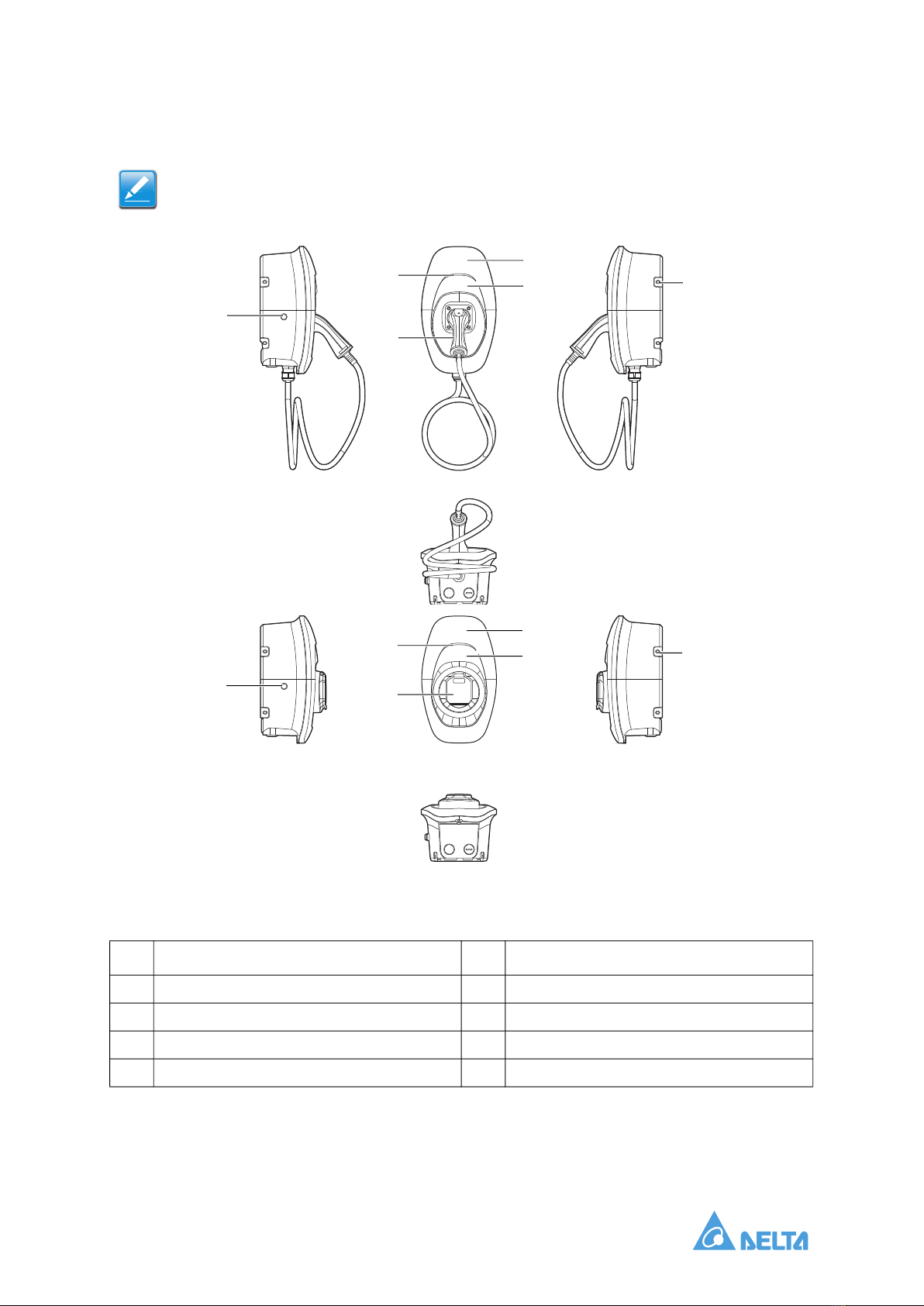
Delta AC MAX User manual

AC MAX Charger
Installation and Operation Manual
Version: 1.0.0

0-i Installation and Operation Manual

Installation and Operation Manual ii
TABLE OF CONTENTS
About the Product . . . . . . . . . . . . . . . . . . . . . . . . . . . . . . . . . . . . . . . . . . 1
Model Series . . . . . . . . . . . . . . . . . . . . . . . . . . . . . . . . . . . . . . . . 1
Product Overview . . . . . . . . . . . . . . . . . . . . . . . . . . . . . . . . . . . . . 2
Component List . . . . . . . . . . . . . . . . . . . . . . . . . . . . . . . . . . . . . . 3
Recommended Tools and Accessories . . . . . . . . . . . . . . . . . . . . 3
Installation Environment and Safety Instructions . . . . . . . . . . . . . 4
Installation and Operating Instructions . . . . . . . . . . . . . . . . . . . . . . . . . . 6
Preparations before Starting . . . . . . . . . . . . . . . . . . . . . . . . . . . . 6
Recommended Installation Space . . . . . . . . . . . . . . . . . . . . . . . . 6
Installation Steps . . . . . . . . . . . . . . . . . . . . . . . . . . . . . . . . . . . . . 7
Operating Instructions . . . . . . . . . . . . . . . . . . . . . . . . . . . . . . . . 12
Status Indicator . . . . . . . . . . . . . . . . . . . . . . . . . . . . . . . . . . . . . 12
Troubleshooting . . . . . . . . . . . . . . . . . . . . . . . . . . . . . . . . . . . . . . . . . . 13
Specifications . . . . . . . . . . . . . . . . . . . . . . . . . . . . . . . . . . . . . . . . . . . . 14
Cleaning . . . . . . . . . . . . . . . . . . . . . . . . . . . . . . . . . . . . . . . . . . . . . . . . 15
Warranty . . . . . . . . . . . . . . . . . . . . . . . . . . . . . . . . . . . . . . . . . . . . . . . . 15
Disposal . . . . . . . . . . . . . . . . . . . . . . . . . . . . . . . . . . . . . . . . . . . . . . . . 15

Installation and Operation Manual iii
Conventions
General Conventions
The following conventions are used in this manual:
Typographical Conventions
The following typographical conventions are used in this document:
Italics
Indicates book titles, directory names, file names, path names, and program/process names.
Constant width
Indicates computer output shown on a computer screen, including menus, prompts, responses to
input, and error messages.
Constant width bold
Indicates commands or information literally entered by a user on the computer. Variables contained
within user input are shown in angle brackets (< >).
Bold italics
Indicates keyboard keys that are pressed by the user.
Note:
Indicates additional information that is relevant to the current process or procedure.
WARNING!
Warning information appears before the text it references to emphasize that the content may
prevent damage to the device or equipment.
CAUTION!
CAUTIONS APPEAR BEFORE THE TEXT IT REFERENCES. CAUTIONS APPEAR IN CAPITAL LETTERS TO
EMPHASIZE THAT THE MESSAGE CONTAINS VITAL HEALTH AND SAFETY INFORMATION.
!
!

Installation and Operation Manual iv
Copyright
The ownership and all intellectual property rights of this Installation and Operation Manual (this “Man-
ual”), including but not limited to the content, data, and figures contained herein, are vested by Delta
Electronics, Inc. (“Delta”). The Manual can only be applied to operation or use of the product. Any dis-
position, duplication, dissemination, reproduction, modification, translation, extraction or any other
usage to the Manual is prohibited without obtaining Delta’s prior written permission. As the product will
be developed and improved continuously, Delta may modify or update the Manual from time to time
without any notice. Delta will do its best efforts to keep the Manual updated and maintain the accuracy
of the Manual. Delta disclaims any kinds or forms of warranty, guarantee or undertaking, either
expressly or implicitly, including but not limited to the completeness, accuracy, non-infringement, mer-
chantability or fitness for particular purpose or usage.
Copyright © 2020 Delta Electronics, Inc. All Rights Reserved.
Intended Use
The device is intended for indoor and outdoor use for charging Battery Electric Vehicle or Plug-in Hybrid
Electric Vehicle. Do not use the device to charge or supply other devices. The device is designed for
installation on a wall or pedestal and shall comply with the national regulations for installing and con-
necting the charger.
The device is developed, manufactured, tested and documented according to the safety standards. If
you comply with the instructions and safety information described for its intended use, the product nor-
mally will not pose any danger in terms of property damage or to the health of people. The instructions
contained in this manual shall follow to the letter. Otherwise, sources of danger may be produced or
safety equipment may be rendered inoperable.

About the Product Model Series
1-1 Installation and Operation Manual
About the Product
Model Series
The following describes the segmentation used to describe the basic features of each available model.
Figure 1. Naming Segments
Table 1: Naming Segments
Segment Item Description
1
702: 7kW
113: 11kW
223: 22kW
Indicates maximum output power
2
A: IEC 62196-2 Type 1 Plug
B: IEC 62196-2 Type 2 Plug
C: IEC 62196-2 Type 2 Socket
D: IEC 62196-2 Type 2 Socket
with shutter
Indicates charging connector or socket type
3
0: No cable
5: 5 m Indicates charging connector cable length
4
C: 380-415 Vac, 3-Phase (L1,
L2, L3, N, PE), 50/60 Hz
E: 208-240 Vac, 1-Phase (L1,
N, PE or L1, L2, PE), 50/60
Hz, actual rating is country-
specific
Indicates line voltage input rating
5 N: Bluetooth only Indicates network communication options
6 A: Key only Indicates management options
EVAAE 223 B 5 C N A
6th segment
5th segment
4th segment
3rd segment
2nd segment
1st segment

About the Product
Installation and Operation Manual 2
Product Overview
Figure 2. Overview
Note:
Availability of features is subject to the model.
Table 2: Overview
No. Item No. Item
1 Key switch 5 Front cover
2 LED indicator 6 Middle cover
3 Charging Connector 7 Mounting holes
4 Socket or Socket with shutter
2
1
5
3
67
2
1
5
4
67

About the Product Component List
1-3 Installation and Operation Manual
Component List
Recommended Tools and Accessories
The following tools are recommended for the installation of product:
Recommended Tools
Torque wrench
Electro drill for masonry walls.
Phillips #3 screwdriver for securing cable holder.
Torx T20 screwdriver for securing front cover and middle cover.
Torx T30 screwdriver for securing mounting bracket.
As securing mounting bracket, using Phillips #2 screwdriver for wooden walls or 10mm Hex
wrench for masonry walls.
Terminal crimper for input wire.
Mounting bracket x 1 Mounting template x 1 User manual x 1
No. 8 wood screws x 2 Torx T30 mounting bolts x 4 1/4 inch expansion bolts x 2
Cable holder x 1
(For charging connector version) Key for key switch x 2
Installation and
Operation Manual

About the Product
Installation and Operation Manual 4
Installer-Supplied Components for Input Wire
Conduit of appropriate trade size for power wires - M32.
Cable gland (IP55) for input wire to ensure water resistance.
DIN 46228-4 Cord end terminal:
Installation Environment and Safety Instructions
Before you start, please read the following instructions:
Installation Site Selection
AC MAX can be installed in both indoor and outdoor environments. It is necessary to consider the
installation conditions and protection at the site:
Follow local electrical regulation and installation standards.
Consider the emergency routes at the installation site.
Do not install the device at potentially explosive atmosphere areas (Ex areas).
Risk of Electric Shock
Supervision is required when operating this device in the presence of children.
Do not use adaptors, conversion adaptors or cord extension sets with the product.
Do not insert your fingers into the EV charging connector.
Do not replace any components of the product.
Do not use this product if the flexible power cord or EV charging cable is frayed, the insulation is
broken, or the device shows signs of damage.
Do not use this product if the enclosure or the EV charging connector is broken, cracked, open,
or shows any signs of damage.
A device employing pressure terminal connectors for field wiring connections shall be provided
along with instructions specifying a range of values or nominal value of tightening torque to be
applied to the clamping screws of the terminal connectors.
Circuit Breaker Specifications
To reduce the risk of fire, only connect to a circuit with a circuit breaker specification conforming to IEC 60898-1.
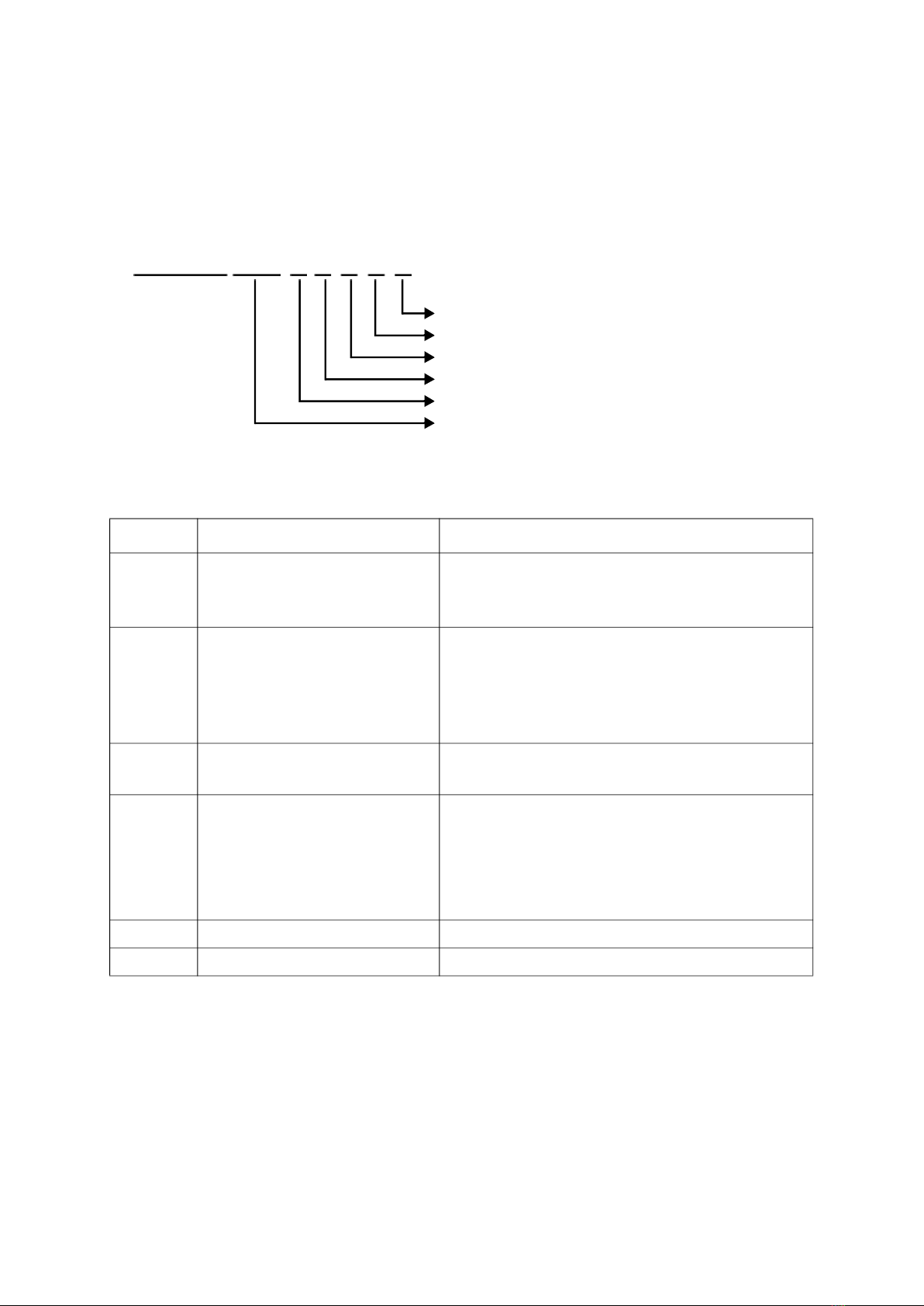
Current 16A 32A
Pin length 18 mm 18 mm
Wire range 4 mm210 mm2
Read all the instructions regarding the risk of electric shock:
Table 3: Circuit Breaker Specifications
Model Circuit Breaker Specification
EVAAE702 40A min., 230V min., 2 poles
EVAAE113 20A min., 400V min., 4 poles
EVAAE223 32A min., 400V min., 4 poles
18mm

About the Product Installation Environment and Safety Instructions
1-5 Installation and Operation Manual
Safety Instructions
Disconnect all electrical power prior to installing the product. Failure to do so may result in elec-
tric shock, physical injury or damage to the electrical system and charging unit.
The product can only be installed by licensed contractors, or licensed electricians in accordance
with all applicable state, local and national electrical codes and standards in a location with non-
restricted access.
Before installing the product, review this manual carefully and consult with licensed contractors,
licensed electricians, and installation experts to ensure compliance with local building practices,
climate conditions, safety standards, and state and local codes.
Use appropriate protection when connecting to the main power distribution cable.
Danger of electrical shock or injury. Turn OFF all power at the panel board or load center before
working inside the equipment or removing any component. Do not remove circuit protective
devices or any other component until the power is turned OFF.
The product must be connected to a grounded, metal, permanent wiring system or an equip-
ment grounding conductor must be run with the circuit conductors and connected to the equip-
ment-grounding terminal or lead on the product.

Installation and Operating Instructions
Installation and Operation Manual 6
Installation and Operating Instructions
Preparations before Starting
Recommended Installation Positions
When considering installation positions, make sure EV can be easily connected with charger and have
enough space for maintenance.
Figure 3. Recommended Installation Locations
Recommended Installation Space
Installers shall follow applicable accessibility requirements for the mounting position. The unit must be
mounted at a height between 800 mm (31.5 inches) and 1200 mm (47.2 inches) above ground.
Figure 4. Recommended Installation Space
Table 4: Recommended Installation Locations
No. Item
1 Recommended position
2 Alternative position
1
2
1
2
500mm 500mm
200mm
800mm
~1200mm
500mm500mm
500mm
Front View
Overview

Installation and Operating Instructions Installation Steps
1-7 Installation and Operation Manual
Installation Steps
Mark Drill Holes
Secure Mounting Bracket
1. The cable holder is optional and depicted in the following figure for demonstration purposes.
The following are recommended bolt types:
Masonry walls: 1/4” expansion bolts.
Torque: 8.8 N·m (78 lb·in)
Finished walls supported by wood studs: #8 wood screws of 2” or above screw length.
Torque: 3 N·m (26 lb·in)
Figure 6. Installing a Mounting Bracket in a Masonry or Finished Walls Location
The product is a stationary wall-mounted
equipment. It includes a wall mounting template
to mark the screw locations for the mounting
bracket and cable holder (optional).
Figure 5. Template for Marking Drill Holes

Installation and Operating Instructions
Installation and Operation Manual 8
2. Align the product with the screw holes on the mounting bracket.
3. Secure the product on the mounting bracket with the supplied Torx T30 screws.
Torque: 1.5 N·m (13 lb·in)
Figure 7. Installing a Charger
Remove Front and Middle Covers
1. Remove the screw located at the bottom of the front cover by using a Torx T20 screwdriver.
2. Pull the front cover upward to separate from the charger.
Figure 8. Removing Front Cover
1
2

Installation and Operating Instructions Installation Steps
1-9 Installation and Operation Manual
Configure Dip Switches
1. Authorization mode: Choose the pin 2 to configure the authorization mode for key switch or bluetooth.
2. Grounding system: Choose the pin 3 to configure the grounding system for TT/TN or IT system.
3. Remove the screw located at the middle
cover by using a Torx T20 screwdriver.
4. Remove the middle cover.
Figure 9. Removing Middle Cover
Configure the dip switches for authorization
mode, grounding system, and maximum current
setting.
Figure 10. Dip Switch
Table 5: Authorization mode
Configuration Function Configuration Function
Key switch (Default) Bluetooth
Table 6: Grounding System
Configuration Function Configuration Function
TT/TN (Default) IT
3
0
1
ON
0
1
ON
0
1
ON
0
1
ON

Installation and Operating Instructions
Installation and Operation Manual 10
3. Maximum current ratings: Choose the pin 4-6 to configure the maximum output current ratings.
Connect Input Wire
1. Install the copper wire as described. Insert the corresponding input wire into the terminal.
Copper wire type: 10 mm2, 70ºC.
Note:
Bottom-fed for indoor/outdoor installation, and rear fed for indoor installation.
Figure 11. Connecting the Input Wire
Table 7: Max Current Ratings
Configuration Max. Current Ratings Configuration Max. Current Ratings
000
6A (Default)
001
16A
100
8A
101
20A
010
10A
011
24A
110
12A
111
32A
ON
0
1
ON
0
1
ON
0
1
ON
0
1
ON
0
1
ON
0
1
ON
0
1
ON
0
1
L1 L2 PENL3

Installation and Operating Instructions Installation Steps
1-11 Installation and Operation Manual
2. Terminal block instructions. Make sure the terminal block is secured correctly.
Figure 12. Securing a Terminal Block
Secure Middle and Front Covers
1. Recover the middle cover on the charger.
2. Secure the middle cover by using a Torx T20 screwdriver.
Torque: 1.2 N·m (10.5 lb·in)
3. Recover the front cover on the charger.
4. Secure the screw located at the bottom of the front cover by using a Torx T20 screwdriver.
Torque: 0.5 N·m (4.4 lb·in)
Figure 13. Recovering a Middle Cover
Figure 14. Recovering a Front Cover
18
1 2 3
WrongWrongWrong
1
3
2

Installation and Operating Instructions
Installation and Operation Manual 12
Operating Instructions
Basic Version
Status Indicator
Fault Event
The key switch is located on the side of the
product. Charger is powered on when the key
switch is in the On position.
Figure 15. Enabling the Charging Function
Status Description
Black Power off.
Yellow, fast flashing Initial configuration and self-test.
Blue Standby mode (not connecting to EV).
Yellow Ready to charge (connecting to EV).
Blue, slow flashing Charging in progress.
Green Charging process completed.
Red, slow flashing Refer to fault event.
Red Self-test failed. Please contact Customer Support.
Status Description Action
Red, 1 Flash High/under voltage
protection
The charger will be auto-recovery once the voltage is
normal. If not, please restart the charger or contact
Customer Support.
Red, 2 Flashes Ground fault protection. Check the ground system, and wait for recovery.
Red, 3 Flashes Ground does not correctly
connect to the charger. Check if ground (PE) is well connected.
Red, 4 Flashes Over current protection. Unplug the charging connector and plug it again.
Red, 5 Flashes Over temperature
protection.
Wait for recovery and check if any heat source around
the charger. If yes, please try to remove the heat source.
Red, 6 Flashes Input mis-wired. Swap the Line (L) and Neutral (N).
Red, 7 Flashes Control pilot signal error. Please contact Customer Support.
o on
o on

Troubleshooting Status Indicator
1-13 Installation and Operation Manual
Troubleshooting
Contact Customer Support if the product appears to malfunction or if the LED indicators display a fault
event. DO NOT open the product, touch or remove the circuit protective devices or any other compo-
nent.
Situation Action
Indicator does not light
1. Make sure the power input is connected correctly and the power
is within operating range of the unit.
2. Power cycle the product.
3. If the problem persists, contact Customer Support.
Indicator does not flash after
plugging charging connector
1. Check if the charging connector is fully inserted to EV
2. Check if the battery is full on EV
3. If the problem persists, contact Customer Support.
Indicator starts to flash in red
while charging
1. Wait until the temporary error is resolved and the product returns
to normal condition, typically less than 10 seconds.
2. Unplug the charging connector.
3. Power cycle the product.
4. If the situation persists, contact Customer Support.
Indicator illuminates in red
1. It might be a critical error (e.g. hardware fault).
2. Unplug the charging connector.
3. Power cycle the product.
4. If the situation persists, contact Customer support.

Specifications
Installation and Operation Manual 14
Specifications
Model Basic
Charging mode Mode 3
Charging interface IEC 62196-2: Type 1 plug, Type 2 plug, Type 2 socket, and Type 2 socket
with shutter
Input/Output rating
208-240 Vac, single-phase, 32 A max., 50 Hz
380-415 Vac, three-phase, 32 A max., 50 Hz
Input wiring
L1, N, and PE or L1, L2, and PE for single-phase
L1, L2, L3, N, and PE for three-phase
Standby power < 2.6 W
Altitude 4000 m
Internal residual current
detection DC 6 mA, AC 30 mA
Surge protection Class II
Electrical protection
Over current protection, short circuit protection, over voltage protection,
under voltage protection, ground fault protection, surge protection, over
temperature protection
Cold load pick-up Randomized delay between 5 and 100 seconds before the charge resume
after power outages.
Status indicators Blue, yellow, green, red
Buttons/Switches Key switch
Operating temperature -30ºC to +50ºC (-22ºF to +122ºF)
Storage temperature -40ºC to +80ºC (-40ºF to +176ºF)
Humidity < 95% related humidity, non-condensing
Cable length 5 m, straight cable
Ingress protection IP55 for indoor and outdoor
Impact protection IK10
Cooling Natural cooling
Dimension (H x W x D) 371 x 218 x 167 mm (14.6 x 8.6 x 6.6 inch), excluding charging cable,
mounting bracket and cable holder
Net weight 3.9 kg
Compliance/certificate CE mark

Cleaning Status Indicator
1-15 Installation and Operation Manual
Cleaning
Regular cleaning of charger is required while standby state. Using a soft damp cloth with clear water is
highly recommended and make sure no water enters the charging connector.
Warranty
Customer Service can provide more information on the terms of the warranty. However, the following
cases are not covered by the warranty.
Defects or damage caused by not using the product as specified in the Installation and Opera-
tion Manual.
Costs and damage caused by repair work which is not provided by Delta approved authorized
specialist or electrician.
Disposal
The charger is an electronic device and must be disposed of separately from normal
house wastes. Please have it disposed in compliance with the waste disposal and
recycle local regulation.
Other manuals for AC MAX
3
Table of contents
Other Delta Batteries Charger manuals

Delta
Delta EV-4120 User manual

Delta
Delta AC MAX User manual

Delta
Delta AC Wallbox User manual

Delta
Delta EV-3226 User manual

Delta
Delta QI-1036 User manual

Delta
Delta 1902435 User manual

Delta
Delta MOOVair User manual

Delta
Delta AC MAX User manual

Delta
Delta DC Wallbox Stand User manual

Delta
Delta AC MAX User manual

Delta
Delta 1902275 User manual

Delta
Delta QI-1038 User manual

Delta
Delta LI-ION Series User manual

Delta
Delta AWC-102 User manual

Delta
Delta QI-1037 User manual

Delta
Delta QI-1045 User manual

Delta
Delta QI-1034 User manual

Delta
Delta 1902335 User manual

Delta
Delta SMP-90W12 User manual

Delta
Delta QI-1028 User manual