Delta AC MAX User manual

Installation and operation manual
AC MAX
EU-Basic version
Version: 1.0.4
Issue date: 2023-01
AC MAX Basic Firmware Version 5.1

v1.0.3
2
Table of Contents
1
Information ........................................................................................................................................... 3
1.1
Copyright .................................................................................................................................... 3
1.2
Intended use ............................................................................................................................... 3
1.3
Safety instructions ....................................................................................................................... 3
1.4
Operator‘s duty of supervision .................................................................................................... 4
1.5
Model series ............................................................................................................................... 5
1.6
Product overview ........................................................................................................................ 6
2
Installation ............................................................................................................................................ 9
2.1
Prepartion before start ................................................................................................................ 9
2.2
Installation steps ....................................................................................................................... 10
3
Operation ........................................................................................................................................... 21
3.1
(Optional) Connect the AC MAX App ......................................................................................... 22
3.2
Start charging ............................................................................................................................ 22
3.3
Stop charging ............................................................................................................................ 22
4
LED Indicator ...................................................................................................................................... 22
4.1
Fault events............................................................................................................................... 23
4.2
Symbol description.................................................................................................................... 24
5
Troubleshooting .................................................................................................................................. 24
6
Specifications ...................................................................................................................................... 25
7
Cleaning .............................................................................................................................................. 26
8
Warranty ............................................................................................................................................. 26
9
Disposal .............................................................................................................................................. 26

v1.0.3
3
1 Information
1.1 Copyright
The ownership and all intellectual property rights of this Installation and Operation Manual (this “Manual”),
including but not limited to the content, data and figures contained herein are vested by Delta Electronics, Inc.
(“DELTA”). The Manual can only be applied to operation or use of the device. Any disposition, duplication,
dissemination, reproduction, modification, translation, extraction or any other usage to the Manual is prohibited
without obtaining DELTA’s prior written permission. As the product will be developed and improved
continuously, DELTA may modify or update the Manual from time to time without any notice. DELTA disclaims
any kinds or forms of warranty, guarantee or undertaking, either expressly or implicitly, including but not limited
to the completeness, accuracy, non-infringement, merchantability or fitness for particular purpose or usage.
Copyright © 2021 Delta Electronics, Inc. All Rights Reserved.
1.2 Intended use
The device is developed, manufactured, tested and documented according to the safety standards. If you
comply with the instructions and safety instructions described for its intended use, the product normally will
not pose any danger in terms of property damage or to the health of people. The instructions contained in this
manual shall follow to the letter. Otherwise, sources of danger may be produced or safety equipment may be
rendered inoperable.
This device may only be used to charge Battery Electric Vehicle or Plug-in Hybrid Electric Vehicle in
accordance with the following regulations:
Mode 3 charging according to IEC 61851-1 for electric vehicles with non-gas discharged batteries.
Use with plugs and sockets according to IEC 62196.
In addition, the following conditions apply for intended use:
The device is exclusively for stationary installation.
The device is designed for installation on a wall or pedestal.
The device can be used for indoors and outdoors.
The following uses are considered as not intended:
The charging of electric vehicles with gassing batteries is not permitted.
1.3 Safety instructions
Before installing, commissioning, and operating of the EVSE, review this manual carefully and consult with
licensed contractors, licensed electricians and installation experts to ensure compliance with local building
practices, climate conditions, safety standards, and state and local codes. DELTA is not responsible for
damage caused by failure to follow the safety instructions and work instructions in this manual.
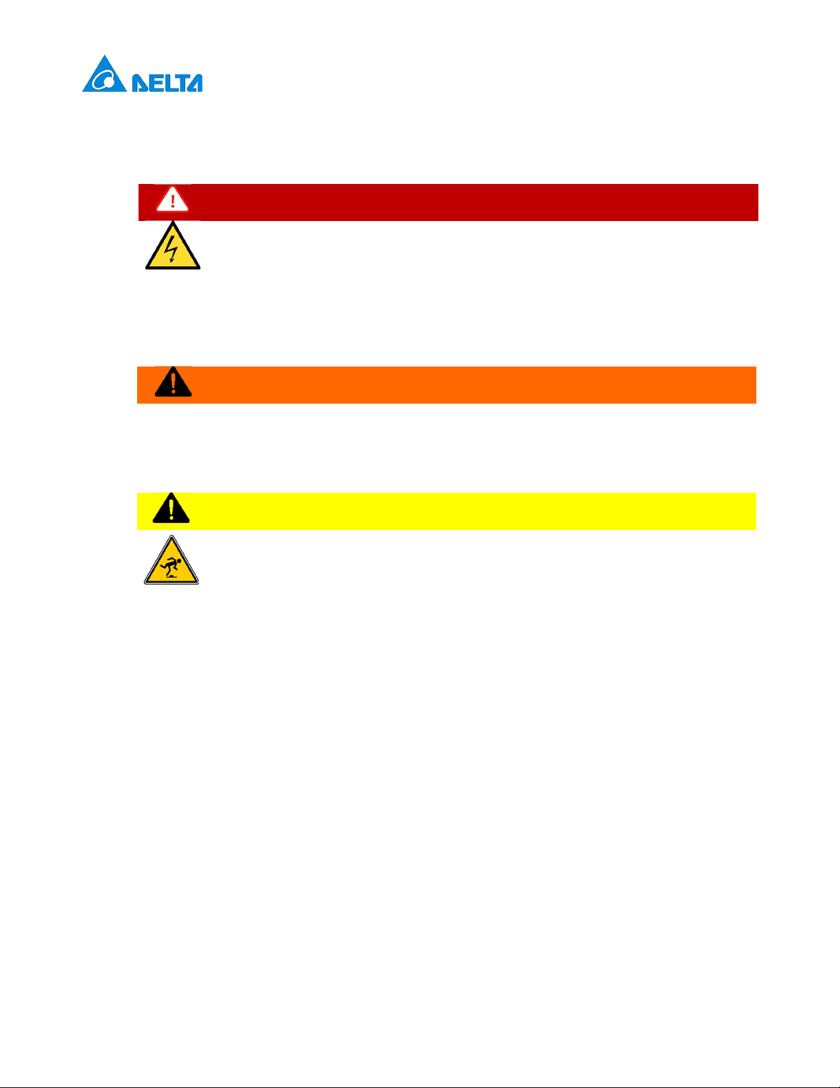
DANGER
Risk of electric shock
Dangerous voltages and currents can occur during operation of the EVSE. Therefore, before
carrying out any work on the EVSE, take the following protective measures:
Disconnect all electrical power prior to installing the EVSE. Failure to do so may result in electric shock,
physical injury or damage to the electrical system and charging unit.
Do not remove circuit protective devices or any other component until all electrical power is disconnected.
Secure the working area against access by unauthorized persons.

v1.0.3
4
The EVSE must be connected to a grounded, metal, permanent wiring system or an equipment grounding
conductor must be run with the circuit conductors and connected to the equipment grounding terminal or
lead on the EVSE.
Use a measuring instrument to check that there is no voltage.
Use appropriate protection when connecting to the main power distribution cable.
DANGER
Risk of electric shock
Dangerous voltages and currents can occur when operating the EVSE.
Do not use the device to charge or supply other devices.
Do not touch the contact pins of the charging plug when operating.
Do not use adapters, conversion adapters or cord extension sets with the EVSE.
Do not use this EVSE if the flexible power cord or charging cable is frayed, the insulation is broken, or
the device shows signs of damage.
WARNING
Close the charging plug with the protective cap when not in use.
Damaged cables may only be replaced by electricians.
Do not use this EVSE if the enclosure or the vehicle connector is broken, cracked, open, or shows any
signs of damage.
Only pull the charging cable out of the charging socket by the charging plug.
CAUTION
Risk of tripping
People can trip over cables lying around.
► Always hang the charging cable in the holder supplied with the EVSE after use.
A device using pressure connectors for field wiring connections must be supplied with instructions that
specify a range or nominal value of the tightening torque to be applied to the terminal screws of the
connectors.
Any repair work as well as the replacement of components on the EVSE may only be carried out by
DELTA. Otherwise the warranty will become void.
Damaged or illegible safety labels must be replaced.
The EVSE can only be installed by licensed contractors, or licensed electricians in accordance with all
applicable state, local and national electrical codes and standards in a location with non-restricted access.
To ensure the ingress protection degree IP55, seal all external connections adequately. Seal unused
connections with the caps provided.
Warning notices, warning symbols and other markings attached to the EVSE by DELTA must not be
removed.
1.4 Operator‘s duty of supervision
As the operator of the EVSE, you are responsible for the safety of the users and its proper use.
As the operator of the EVSE, you are responsible for the safety of particularly vulnerable persons,
especially children. Ensure that such persons maintain a sufficient safety distance from the EVSE and
the charging cable.
Consider the emergency routes at the installation site.
Do not install the device at potentially explosive atmosphere areas (Ex areas).
In case of risk of electric shock, fire or explosion, please press the emergency button immediately, which
will turn off all input and output to ensure safety. Once the emergency button is pressed, the operator
shall be informed and the EVSE shall not restart until the technician reset the EVSE.

v1.0.3
5
1.5 Model series
The following describes the segmentation used to describe the basic features of each available model:
EIAW -
X
XXK
X
X
X
X
X
XX
1
2 3
4
5
6
7
8
Segment Item Description
1
E: AU/NZ, EMEA, SEA,
G: China
J: Japan
T: Taiwan
U: Canada, US
Indicate the available region
2
From 1-99:
7: 7 kW
11: 11 kW
22: 22 kW
Indicates the nominated maximum output power
3 S: Single phase
T: Three phase
Indicates the phase of input rating
4
B: Basic
S: Smart
P: Premium
Indicates the version of EVSE
5
U: SAE J1772 plug
E: IEC 62196-2 plug
S: IEC 62196-2 socket
H: IEC 62196-2 shutter
G: GB/T 20234.2 plug
Indicates the charging interface
6
From 1-9:
5: 5 m
7: 7 m
Indicates the cable length (0 for socket or shutter)
7
From A-Z:
A: Generation A
B: Generation B
Indicates the product generation
8 From 01-99 Indicates the serial code of EVSE

v1.0.3
6
1.6 Product overview
1.6.1 Scope of delivery
Part Description Part Description
EVSE*
1x
Mounting bracket
1x
Template
1x
Torx T30 mounting bolts
4x
No. 8 wood screws
2x
1/4 inch expansion bolts
2x
Quick installation guide
1x
Safety instructions
1x

v1.0.3
7
Part Description Part Description
Cable gland
1x
wood screws
2x
Control board
1x
Cable holder*
(For plug version only)
1x
Key
1x
*Depends on model configuration
1.6.2 Recommended tools
The following tools are recommended for the installation of product:
Part
Description
Electro drill Used for masonry walls
Pencil
Spirit level
Terminal crimper Crimping input wire
Torque wrench
Torque screwdriver (cross) Securing mounting bracket to masonry walls or stand
Torque screwdriver (slotted) Securing mounting bracket to masonry walls or stand
Torx T20 screwdriver Securing front cover and middle cover
Torx T30 screwdriver Securing mounting bracket

v1.0.3
8
1.6.3 Installer-supplied components
Installers may prepare the following parts:
1. Conduit of appropriate size or cable gland (M32) for input power wires to ensure the water resistance.
2. DIN 46228-4 Cord end terminal:
Please use the cord end terminal for split conductors while installation.
Current 16 A 32 A
Pin length 18 mm 18 mm
Wire range 4
mm
10
mm
3. Upstream breakers:
To reduce the risk of fire, only connect to a circuit with circuit breaker conforming to IEC 60898-1.
Model Circuit breaker specification
EIAW-E7K 40A min., 230V min., 2 poles, Type B
EIAW-E11K 20A min., 400V min., 4 poles, Type B
EIAW-E22K 40A min., 400V min., 4 poles, Type B
1.6.4 Overview of components
1. Mounting bracket
2. Key switch
3. Body
4. LED bar
5. Cable gland
6. Middle cover
7-A. Vehicle connector
7-B. Socket/ socket with shutter
8. Front cover
9. Water proof cap

v1.0.3
9
2 Installation
Before you start, please read the following instructions.
2.1 Prepartion before start
2.1.1 Installation site selection
AC MAX can be installed in both indoor and outdoor environments. It is necessary to consider the installation
conditions and protection at the site:
Follow local electrical regulation and installation standards.
Consider the emergency routes at the installation site.
Do not install the device at potentially explosive atmosphere areas (Ex areas).
2.1.2 Recommended installation positions
When considering installation positions, make sure EV can be easily connected with EVSE and have enough
space for maintenance.
1. Recommended position
2. Alternative position
2.1.3 Recommended installation space
Installers shall follow applicable accessibility requirements for the mounting position. The EVSE shall be
mounted at a height between 800 mm (31.5 inches) and 1200 mm (47.2 inches) above ground.
Front view Top view

v1.0.3
10
2.1.4 (Optional) emergency button
Installers shall install a waterproof box
(at least IP 44) and an isolator switch that both complies with local
codes. Installers assemble the MCB
and Type
A RCD in the waterproof box, then install the Isolator switch at
front end of the box, as shown in below circuit wiring diagram.
Input phase
Diagram
Single phase
Three phase
2.2 Installation steps
2.2.1 Remove front cover and middle cover
1. Remove the screw located at the bottom of front cover by
using a Torx T20 screwdriver.
2. Pull the front cover upward to separate from the EVSE.

v1.0.3
11
3. Remove the screw located at the middle cover by using a
Torx T20 screwdriver.
4. Remove the middle cover.
2.2.2 Mark drill holes
The EVSE is a stationary wall-mounted equipment. Using the
template to mark the screw locations for the mounting bracket
and cable holder (optional).
2.2.3 Secure mounting bracket
1. The cable holder is optional and depicted in the figure for
demonstration purposes. The following are
recommended bolt types:
Masonry walls: 1/4" expansion bolts.
Torque: 8.8 N·m (78 lb·in)
Finished walls supported by wood studs: #8 wood
screws of 2" or above screw length.
Torque: 3 N·m (26 lb·in)

v1.0.3
12
2. Align the EVSE with the screw holes on the mounting
bracket.
3. Secure the EVSE on the mounting bracket with the
supplied Torx T30 screws.
Torque: 1.5 N·m (13 lb·in)
2.2.4 Configure dip switches
Configure the dip switches with following steps
2.2.4.1 Phase unbalance protection
Choose the pin 1 to enable or disable the phase unbalance protection. When the function is enabled, the
protection will limit the phase unbalance to 15 A.
Configuration Function Configuration Function
Disable (Default)
Enable
Note: The unbalance current rating can be changed via Bluetooth with the AC MAX App. The configured
unbalance must comply with the specifications of the grid code in force at your installation site.
The password to reach this setting in the AC MAX App is: 0000

v1.0.3
13
2.2.4.2 Authorization mode
Choose the pin 2 to configure the authorization mode for Bluetooth availability.
Configuration Function Configuration Function
Key switch (Default)
Bluetooth
If the pin 2 is set to OFF (left), the key switch has to be turned ON to start a charging session. The Bluetooth
authentication is deactivated in this configuration but the app can still connect and be used to configure,
monitor and update the wallbox.
If the pin 2 is set to ON (right), the charging session can only be started from the Delta AC MAX App. The key
switch authentication is deactivated in this configuration.
2.2.4.3 Grounding system
Choose the pin 3 to configure the grounding system for TT/TN or IT system.
Configuration Function Configuration Function
TT/TN (Default)
IT
If the pin 3 is set to OFF, the wallbox is configured for TN/TT grids. In this configuration, the wallbox
continuously monitors the availability of the protective earth conductor. If the impedance of this measurement
is too high, the wallbox will indicate the problem by the status LED.
If the pin 3 is set to ON, the wallbox is configured for IT grids. In this configuration, the wallbox monitors that
no protective earth conductor is connected. If the wallbox recognizes the availability of the protective earth
conductor, it will indicate the problem by the status LED.

v1.0.3
14
2.2.4.4 Maximum current setting
Choose the pin 4-6 to configure the maximum output current ratings.
For AC MAX models with a maximum current of 16 A, the configurations 20 A, 24 A and 32 A limit the maximum
output current to 6 A.
Note: There are cars that do not start the charging session at 6 A.
Configuration Max. Current Ratings Configuration Max. Current Ratings
6 A (Default)
16 A
8 A
20 A*
10 A
24 A*
12 A
32 A*
* Depends on model configuration

v1.0.3
15
2.2.5 Connect input wire
1. Install the copper wire as described. The section of copper
wire connected to terminal shall be reserved enough
tolerance to prevent any tension or stress from the external
force.
Note: Copper wire type: 10 mm, 70ºC.
2. Insert the input wire into the terminal accordingly. The cord
end terminal shall be inserted to the end without any
deviation.
Note: Bottom-fed/rear-fed is available for indoor/outdoor
installation with cable gland.
3. Make sure the terminal block is secured
correctly.
Dry contact
Use appropriate wires (0.75 mm) and connect each of them
to the correct terminal connector for dry contact connections
shown on wiring schemes (Left 1: NO, Left 2: COM).
Note:
The product provides a closing signal when unable to close
the output. There are breaker types that trip to stop output
when a closing signal is accepted. It is mandatory requirement
for Netherland and Italy.

v1.0.3
16
2.2.5.1 Wiring diagram
Single phase Three phase
TT
TT
TN-C
TN-C
TN-S
TN-S
TN-C-S
TN-C-S

v1.0.3
17
Single phase Three phase
IT
IT
Note: To fulfill requirements for electrical installations in UK, the following shall be observed.
1. When installed in a TN systems, the supplying circuit shall not include a PEN conductor(combined
protective and neutral) .
2. If the power grid belongs to TN-C-S system, the charger needs to be grounded separately to TT system.
A PME earthing facility shall not be used as the means for the protective conductor contact of a charging
point located outdoors.
2.2.6 (Optional) active power control
Users can control the EVSE with external components (e.g. a ripple control receiver from the power supplier,
a domestic controller, a time switch, a combination lock, a photovoltaic system, etc.).
Note:
1. Ensure that hazardous voltages are isolated safely.
2. The application is taken into consideration for that charging station with a rated power > 12 kVA shall be
equipped with control equipment for network integration via an interruptibility by the network operator in
Germany.
1. Based on the bottom line, attach the control board to the
inner surface of EVSE.

v1.0.3
18
2. Remove the water proof cap and pass through the signal
cable with appropriate conduit or cable gland.
3. Connect the signal cable according to pin definition
(2.2.6.1) and must connect to the Pin 1 (+5V).
Note: suggested wire of signal cable: 1.5 mm2.
4. Assemble the connector
5. Connect the control board

v1.0.3
19
2.2.6.1 Pin definition
User can connect the external component with signal cable based on following configuration. The output power
will be adjusted by the following pin definition once the grid power is limited by network operator. The power
limitation is based on rated output power configured by dip switches (2.2.4.4).
2.2.6.1.1 Configuration A
Connect the signal cable with Pin 1 and Pin 5 as below:
Pin 2 Pin 3 Pin 4 Pin 5 Power limitation
Low Low Low Low Output 100% power
Low Low Low High Stop charging
2.2.6.1.2 Configuration B
Connect the signal cable with Pin 1 to Pin 5 as below:

v1.0.3
20
Pin 2 Pin 3 Pin 4 Pin 5 Power limitation
Low Low Low Low Output 100% power
High Low Low Low Output 87.5% power
Low High Low Low Output 75% power
High High Low Low Output 62.5% power
Low Low High Low Output 50% power
High Low High Low Output 37.5% power
Low High High Low Output 25% power
High High High Low Output 12.5% power
Low Low Low High Stop charging
2.2.7 (Optional) ModBus RTU via RS485
To connect the wallbox with an external (Home) Energy Management System (H)EMS, connect two
communication wires to the RS485 terminal.
The default RS485 settings are 8N1
- Data bits: 8
- Parity bit: None
- Stop bit: 1
- Baud rate: 19200 Baud
Note: The Modbus settings can be changed via Bluetooth with the AC MAX App. The password to reach this setting
in the AC MAX App is: 0000
Other manuals for AC MAX
3
Table of contents
Other Delta Batteries Charger manuals

Delta
Delta 1902435 User manual

Delta
Delta AC MAX User manual

Delta
Delta LI-ION Series User manual

Delta
Delta SMP-90W12 User manual

Delta
Delta AC MAX User manual

Delta
Delta QI-1036 User manual

Delta
Delta QI-1038 User manual

Delta
Delta EV-3226 User manual

Delta
Delta AC Wallbox User manual

Delta
Delta 1902335 User manual

Delta
Delta QI-1028 User manual

Delta
Delta QI-1045 User manual

Delta
Delta QI-1037 User manual

Delta
Delta AC MAX User manual

Delta
Delta 1902275 User manual

Delta
Delta QI-1034 User manual

Delta
Delta DC Wallbox Stand User manual

Delta
Delta EV-4120 User manual

Delta
Delta MOOVair User manual

Delta
Delta AWC-102 User manual