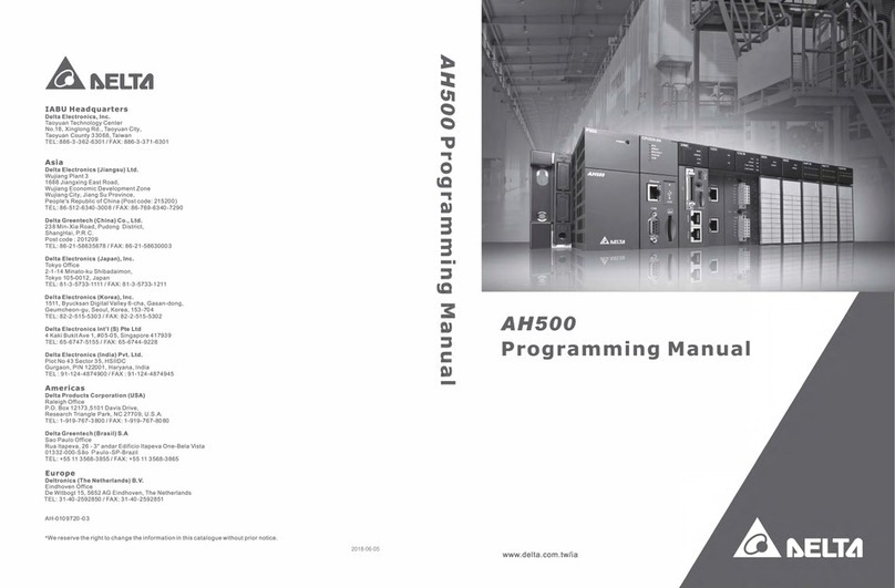
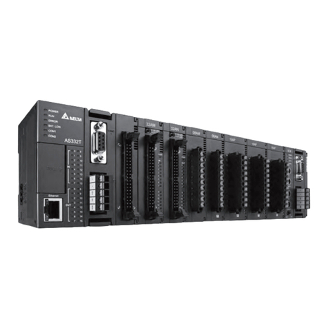
Delta AH500 series User manual

Industrial Automation Headquarters
Delta Electronics, Inc.
Taoyuan Technology Center
No.18, Xinglong Rd., Taoyuan District,
Taoyuan City 33068, Taiwan
TEL: 886-3-362-6301 / FAX: 886-3-371-6301
Asia
Delta Electronics (Shanghai) Co., Ltd.
No.182 Minyu Rd., Pudong Shanghai, P.R.C.
Post code : 201209
TEL: 86-21-6872-3988 / FAX: 86-21-6872-3996
Customer Service: 400-820-9595
Delta Electronics (Japan), Inc.
Tokyo Oce
Industrial Automation Sales Department
2-1-14 Shibadaimon, Minato-ku
Tokyo, Japan 105-0012
TEL: 81-3-5733-1155 / FAX: 81-3-5733-1255
Delta Electronics (Korea), Inc.
Seoul Oce
1511, 219, Gasan Digital 1-Ro., Geumcheon-gu,
Seoul, 08501 South Korea
TEL: 82-2-515-5305 / FAX: 82-2-515-5302
Delta Energy Systems (Singapore) Pte Ltd.
4 Kaki Bukit Avenue 1, #05-04, Singapore 417939
TEL: 65-6747-5155 / FAX: 65-6744-9228
Delta Electronics (India) Pvt. Ltd.
Plot No.43, Sector 35, HSIIDC Gurgaon,
PIN 122001, Haryana, India
TEL: 91-124-4874900 / FAX : 91-124-4874945
Delta Electronics (Thailand) PCL.
909 Soi 9, Moo 4, Bangpoo Industrial Estate (E.P.Z),
Pattana 1 Rd., T.Phraksa,A.Muang,
Samutprakarn 10280, Thailand
TEL: 66-2709-2800 / FAX : 662-709-2827
Delta Electronics (Australia) Pty Ltd.
Unit 20-21/45 Normanby Rd., Notting Hill Vic 3168,Australia
TEL: 61-3-9543-3720
Americas
Delta Electronics (Americas) Ltd.
Raleigh Oce
P.O. Box 12173, 5101 Davis Drive,
Research Triangle Park, NC 27709, U.S.A.
TEL: 1-919-767-3813 / FAX: 1-919-767-3969
Delta Electronics Brazil
São Paulo Sales Oce
Rua Itapeva, 26 - 3°, andar Edicio Itapeva,
One - Bela Vista 01332-000 - São Paulo - SP - Brazil
TEL: 55-12-3932-2300 / FAX: 55-12-3932-237
Delta Electronics International Mexico S.A. de C.V.
Mexico Oce
Gustavo Baz No. 309 Edicio E PB 103
Colonia La Loma, CP 54060
Tlalnepantla, Estado de México
TEL: 52-55-3603-9200
*We reserve the right to change the information in this catalogue without prior notice.
EMEA
Headquarters: Delta Electronics (Netherlands) B.V.
Sales: Sales.IA.EMEA@deltaww.com
Marketing: Marketing.IA.EMEA@deltaww.com
Technical Support: iatechnicalsupport@deltaww.com
Customer Support: Customer-Support@deltaww.com
Service: Service.IA.emea@deltaww.com
TEL: 31(0)40 800 3900
BENELUX: Delta Electronics (Netherlands) B.V.
De Witbogt 20,5652 AG Eindhoven,The Netherlands
Mail: Sales.IA.Benelux@deltaww.com
TEL: 31(0)40 800 3900
DACH: Delta Electronics (Netherlands) B.V.
Coesterweg 45,D-59494 Soest,Germany
Mail: Sales.IA.DACH@deltaww.com
TEL: 49(0)2921 987 0
France: Delta Electronics (France) S.A.
ZI du bois Challand 2,15 rue des Pyrénées,
Lisses, 91090 Evry Cedex, France
Mail: Sales.IA.FR@deltaww.com
TEL: 33(0)1 69 77 82 60
Iberia: Delta Electronics Solutions (Spain) S.L.U
Ctra. De Villaverde a Vallecas, 265 1º Dcha Ed.
Hormigueras – P.I. de Vallecas 28031 Madrid
TEL: 34(0)91 223 74 20
Carrer Llacuna 166, 08018 Barcelona, Spain
Mail: Sales.IA.Iberia@deltaww.com
Italy: Delta Electronics (Italy) S.r.l.
Via Meda 2–22060 Novedrate(CO)
Piazza Grazioli 18 00186 Roma Italy
Mail: Sales.IA.Italy@deltaww.com
TEL: 39 039 8900365
Russia: Delta Energy System LLC
Vereyskaya Plaza II, oce 112 Vereyskaya str.
17 121357 Moscow Russia
Mail: Sales.IA.RU@deltaww.com
TEL: 7 495 644 3240
Turkey: Delta Greentech Elektronik San. Ltd. Sti. (Turkey)
Şerifali Mah. Hendem Cad. Kule Sok. No:16-A
34775 Ümraniye – İstanbul
Mail: Sales.IA.Turkey@deltaww.com
TEL: 90 216 499 9910
GCC: Delta Energy Systems AG (Dubai BR)
P.O. Box 185668, Gate 7, 3rd Floor, Hamarain Centre
Dubai, United Arab Emirates
Mail: Sales.IA.MEA@deltaww.com
TEL: 971(0)4 2690148
Egypt + North Africa: Delta Electronics
Unit 318, 3rd Floor, Trivium Business Complex, North 90 street,
New Cairo, Cairo, Egypt
Mail: Sales.IA.MEA@deltaww.com
AH500 Hardware &
Operation Manual
www.deltaww.com
AH500 Hardware & Operation Manual
AH-0109420-06
2021/03/25

AH500 Hardware and Operation Manual
Revision History
Versio
n
Revision Date
1
st
1. The first version was published.
2013/03/28
2nd
2. The information about AHPS15-5A, AH32AM10N-5A,
AH32AM10N-5C, AH16AR10N-5A, AH32AN02T-5A,
AH32AN02T-5C, AH32AN02P-5A, AH32AN02P-5C,
AH08AD-5C, AH08DA-5C, AH08PTG-5A, AH15PM-5A,
AH10PFBM-5A, AH10PFBS-5A, AH10COPM-5A,
AHRTU-PFBS-5A, AHAADP01/02EF-5A, and
DVPAETB-IO34C is added to all chapters.
3. The storage temperature, the program capacity of
AHCPU500, the specifications for the input/output
relays, the functional specifications for the analog
input/output modules, the electrical specifications for
the temperature measurement modules, the response
characteristics of the input terminals on AH05PM-
5A/AH10PM-5A in Chapter 2 are updated.
4. The specifications for AH16AR10N-5A, and, the
specifications for AH15PM-5A, and the specifications
for AHPS15-5A are added to Chapter 2.
5. Section 4.2.1 is updated.
6. Section 5.1.1 is updated.
7. Point (6) is added to section 6.6.1.
8. Section 9.3.2.1 is updated.
9. Section 11.2.3 is updated, and section 11.3 is added
to Chapter 11.
10.The troubleshooting for new models is added to
Chapter 12.
11.The AH500 addresses of the T devices and the AH500
addresses of the C devices in Appendix B are
updated.
2014/06/13
3rd
1. Information concerning AHCPU511-RS2, AHCPU511-
EN, AHCPU521-EN, AHCPU531-EN, AH08AD-5A and
AH08DA-5A is added.
2. Information concerning larger program capacity and
memory, Serial control interface with multiple
functions and high-speed Ethernet communication
interface is updated to section 1.3.
3. Instruction execution speed, maximum number of
Information concerning backplanes which can be
connected is updated in section 2.2.1. Information
concerning AH500 advanced CPU modules is added to
section 2.2.2. Information concerning arrangement of
AH32AN02P-5 input/output terminals is updated in
section 2.4.4. Information concerning Interrupt input
terminals of AH05PM-5A and input signals as well as
terminal X1.2~X1.5 of AH15PM-5A and AH20MC-5A is
updated in section 2.8.1. Informaiton concering the
applicable input/output module is updated in section
2016/08/15

Versio
n
Revision Date
2.11.1.
4. Information concerning latched area in the device
range is updated in section 5.1.4.
5. Information concerning specifications for SD card is
updated in section 7.1.2.
6. Information concerning address is updated in section
8.3.2.
7. Information concerning AHCPU5X0 is added in chapter
9.
8. Information concerning AHCPU5X0 is added to section
11.1, 11.1.4, 11.2, 11.3, and 11.4.
9. Section 12.2.1, 12.2.2, 12.2.3, 12.2.5, 12.3.2, 12.4.1
are updated.
10.Information concerning installation in Windows 8 is
added in Appendix A.
11.Section B.2 is removed from Appendix B.
4th
1. New contents concerning AH15SCM-5A, AHRTU-ETHN-
5A are added in chapter 1.
2. New contents concerning module weights are added in
chapter 2 and I/O connection cable models
input/output terminals of AH series are also updated.
3. New information about EtherNet/IP is added in section
11.5.
4. New contents concerning EtherNet/IP troubleshooting
are added in section 12.2.5 and delete the error codes
16#9B01~16#9B20.
5. New contents concerning installing the USB driver in
Windows 7 and Windows 10 are added in Appendix A.
2017/03/31
5th
1. New contents concerning AH15EN-5A, AHCPU501-
RS2,
AHCPU521-RS2, AHCPU531-RS2, and AHCPU501-EN
are added.
2. New contents concerning AHCPU501-RS2, AHCPU521-
RS2, AHCPU531-RS2, AHCPU501-EN, AH04HC-5A and
redundancy system are added in Chapter 2.
3. Updated contents concerning ISPSoft in Chapter 6, 7
8 and 9.
4. Updated contents concerning applicable memory cards
in Chapter 7.
5. Updated the maximum characters can be input for the
CPU naming. Update the software supported and its
versions for the network I/O module in Chapter 8.
6. Updated parameters for network communication
settings in Chapter 9.
7. Added new product information concerning
AHCPU501-RS2, AHCPU521-RS2, AHCPU531-RS2,
AHCPU501-EN in Chapter 11.
8. Updated troubleshooting procedures, 16#0014,
16#A0FC, and error LED information in Chapter 12.
20180515

Versio
n
Revision Date
6th
1.AH500 Hardware Manual and AH500 Operation Manual
are combined into AH Series Hardware and Operation
Manual to enhance more concise reading experiences.
2.Added contents from Chapter 1 of AH500 Hardware
Manual to Chapter 1 of AH500 Hardware and
Operation Manual and updated ISPSoft operation
images.
3.Added contents from Chapter 3 of AH500 Hardware
Manual to Chapter 2. Added new product information
AHCPU521-DNP, updated CPU module specifications,
including connection limit and electrical isolation.
4.Updated installing information in Chapter 3.
5.Added contents from Chapter 2 and 5 of AH500
Hardware Manual in Chapter 4.
6.Added contents from Chapter 4 of AH500 Hardware
Manual in Chapter 5.
7.Updated ISPSoft and HWCONFIG 4.0 operation
images and descriptions in Chapter 6, 7, 8, and 9.
8.Updated contents in SM table and updated ISPSoft
and HWCONFIG 4.0 in Chapter 11. Updated web
function contents in section 11.4. Added contents of
data tracer in section 11.6 and data logger in section
11.7.
9.Added contents from Chapter 9 of AH500 Hardware
Manual in Chapter 12.
10.Added Appendix C to introduce EMC Standards and
Appendix D to illustrate Maintenance and Inspection.
2021/3/25

i
AH500 Hardware and Operation Manual
Table of Contents
Chapter 1 Introduction
1.1 Introduction............................................................................................... 1-2
1.1.1 Related Manuals ............................................................................... 1-2
1.1.2 Description of Models........................................................................ 1-2
1.2 Overview .................................................................................................. 1-9
1.3 Characteristics.........................................................................................1-11
Chapter 2 Specifications and System Configuration
2.1 General Specifications.............................................................................. 2-3
2.2 Specifications for CPU Modules............................................................... 2-4
2.2.1 AH500 Series Basic CPU Modules ................................................... 2-4
2.2.2 AH500 Series Advanced CPU Modules............................................ 2-6
2.2.3 AH500 Redundancy CPU Module Specification................................ 2-8
2.2.4 Profiles.............................................................................................. 2-9
2.2.5 Dimensions ......................................................................................2-13
2.3 Basic System Configuration ....................................................................2-14
2.3.1 Introduction ......................................................................................2-14
2.3.2 Configuring a Main Backplane .........................................................2-15
2.3.3 Configuring an Extension Backplane................................................2-15
2.3.4 Maximum Extension.........................................................................2-15
2.4 Specifications for Backplanes..................................................................2-16
2.4.1 General Specifications .....................................................................2-16
2.4.2 Profiles.............................................................................................2-17
2.4.3 Dimensions ......................................................................................2-21
2.5 Specifications for the Power Supply Module ...........................................2-24
2.5.1 General Specifications .....................................................................2-24
2.5.2 Profile...............................................................................................2-25
2.5.3 Dimensions ......................................................................................2-26
2.5.4 Arrangement of Terminals................................................................2-27
2.6 Specifications for Digital Input/Output Modules.......................................2-28
2.6.1 General Specifications .....................................................................2-28
2.6.2 Profiles.............................................................................................2-31
2.6.3 Dimensions ......................................................................................2-40
2.6.4 Arrangement of Input/Output Terminals...........................................2-45

ii
2.7 Specifications for Analog Input/Output Modules .....................................2-53
2.7.1 General Specifications.....................................................................2-53
2.7.2 Profiles.............................................................................................2-57
2.7.3 Dimensions......................................................................................2-59
2.7.4 Arrangement of Input/Output Terminals...........................................2-60
2.8 Specifications for Temperature Measurement Modules..........................2-61
2.8.1 BGeneral Specifications...................................................................2-61
2.8.2 Profiles.............................................................................................2-63
2.8.3 Dimensions......................................................................................2-65
2.8.4 Arrangement of Input/Output Terminals...........................................2-66
2.9 Specifications for Network Modules........................................................2-67
2.9.1 General Specifications.....................................................................2-67
2.9.2 Profiles.............................................................................................2-70
2.9.3 Dimensions......................................................................................2-78
2.9.4 Arrangement of Input/Output Terminals...........................................2-82
2.10 Specifications for Motion Control Modules..............................................2-83
2.10.1 General Specifications.....................................................................2-83
2.10.2 Profiles.............................................................................................2-93
2.10.3 Dimensions....................................................................................2-100
2.10.4 Arrangement of Input/Output Terminals.........................................2-104
2.11 Specifications for the Remote I/O Modules...........................................2-109
2.11.1 General Specifications...................................................................2-109
2.11.2 Profiles...........................................................................................2-110
2.11.3 Dimensions....................................................................................2-114
2.12 Space Module and Extension Cables ...................................................2-116
2.12.1 General Specifications...................................................................2-116
2.12.2 Profiles...........................................................................................2-117
2.12.3 Dimensions....................................................................................2-118
Chapter 3 Installing Software
3.1 Installing and Uninstalling ISPSoft ............................................................3-2
3.1.1 Installing ISPSoft................................................................................3-2
3.1.2 Uninstalling ISPSoft...........................................................................3-9
3.2 Installing and Uninstalling COMMGR........................................................3-9
3.2.1 Installing COMMGR.........................................................................3-10
3.2.2 Uninstalling COMMGR.....................................................................3-13

iii
Chapter 4 Installing Hardware
4.1 AH500 Hardware Framework................................................................... 4-2
4.1.1 Component Parts of AH500 Hardware.............................................. 4-2
4.1.2 Installing Modules on a Main Backplane........................................... 4-5
4.1.3 Installing Modules on an Extension Backplane................................. 4-6
4.1.4 Connecting a Main Backplane to an Extension Backplane ............... 4-7
4.2 Warning.................................................................................................... 4-7
4.3 Installation................................................................................................ 4-8
4.3.1 Installation of Modules in a Control Box............................................ 4-8
4.3.2 Mounting a Backplane....................................................................... 4-8
4.3.3 Installing a Dust Cover.....................................................................4-10
4.3.4 Installing a Module ...........................................................................4-11
4.3.5 Installing a Removable Terminal Block ............................................4-12
4.3.6 Installing a Wiring Module................................................................4-15
4.3.7 Connecting Backplanes....................................................................4-16
4.3.8 Connecting a Communication Cable................................................4-17
4.4 Wiring......................................................................................................4-18
4.5 Connecting Power Cables.......................................................................4-19
4.5.1 Precautions......................................................................................4-19
4.5.2 Ground.............................................................................................4-20
4.5.3 Wiring Power Supply Modules .........................................................4-21
4.5.4 Power Consumption.........................................................................4-24
4.6 Wiring CPU Modules...............................................................................4-27
4.6.1 AH500 Basic / Advanced CPU Modules...........................................4-27
4.6.2 AH500 Redundant CPU Modules.....................................................4-27
4.7 Wiring Digital Input/Output Modules........................................................4-30
4.7.1 Wiring AH16AM10N-5A....................................................................4-30
4.7.2 Wiring AH16AM30N-5A....................................................................4-31
4.7.3 Wiring AH16AR10N-5A....................................................................4-32
4.7.4 Wiring AH16AN01S-5A ....................................................................4-33
4.7.5 Wiring AH16AN01R-5A....................................................................4-34
4.7.6 Wiring AH16AN01T-5A ....................................................................4-35
4.7.7 Wiring AH16AN01P-5A ....................................................................4-36
4.7.8 Wiring AH16AP11R-5A....................................................................4-37
4.7.9 Wiring AH16AP11T-5A.....................................................................4-38
4.7.10 Wiring AH16AP11P-5A ....................................................................4-39
4.7.11 Wiring AH32AM10N-5A....................................................................4-40
4.7.12 Wiring AH32AM10N-5B....................................................................4-41

iv
4.7.13 Wiring AH32AM10N-5C...................................................................4-42
4.7.14 Wiring AH32AN02T-5A....................................................................4-43
4.7.15 Wiring AH32AN02T-5B....................................................................4-44
4.7.16 Wiring AH32AN02T-5C....................................................................4-45
4.7.17 Wiring AH32AN02P-5A....................................................................4-47
4.7.18 Wiring AH32AN02P-5B....................................................................4-48
4.7.19 Wiring AH32AN02P-5C....................................................................4-49
4.7.20 Wiring AH64AM10N-5C...................................................................4-51
4.7.21 Wiring AH64AN02T-5C....................................................................4-52
4.7.22 Wiring AH64AN02P-5C....................................................................4-53
4.8 Wiring Digital Input/Output Terminals......................................................4-55
4.8.1 Wiring Digital Input Terminals..........................................................4-55
4.8.2 Wiring Digital Output Terminals .......................................................4-60
4.9 Wiring Analog Input/Output Modules.......................................................4-66
4.9.1 Wiring AH04AD-5A/AH08AD-5A......................................................4-66
4.9.2 Wiring AH08AD-5B..........................................................................4-67
4.9.3 Wiring AH08AD-5C..........................................................................4-67
4.9.4 Wiring AH04DA-5A/AH08DA-5A......................................................4-68
4.9.5 Wiring AH08DA-5B..........................................................................4-69
4.9.6 Wiring AH08DA-5C..........................................................................4-70
4.9.7 Wiring AH06XA-5A ..........................................................................4-71
4.10 Wiring Temperature Measurement Modules...........................................4-72
4.10.1 Wiring AH04PT-5A...........................................................................4-72
4.10.2 Wiring AH08PTG-5A........................................................................4-73
4.10.3 Wiring AH04TC-5A ..........................................................................4-74
4.10.4 Wiring AH08TC-5A ..........................................................................4-74
4.11 Wiring Network Modules.........................................................................4-75
4.11.1 Wiring AH10DNET-5A .....................................................................4-75
4.11.2 Wiring AH10EN-5A / AH15EN-5A....................................................4-76
4.11.3 Wiring AH10SCM-5A.......................................................................4-76
4.11.4 Wiring AH15SCM-5A.......................................................................4-77
4.11.5 Wiring AH10PFBM-5A/AH10PFBS-5A ............................................4-77
4.11.6 Wiring AH10COPM-5A ....................................................................4-78
4.12 Wiring Remote I/O Modules....................................................................4-79
4.12.1 Wiring AHRTU-DNET-5A.................................................................4-79
4.12.2 Wiring AHRTU-PFBS-5A .................................................................4-81
4.12.3 Wiring AHRTU0-ETHN-5A...............................................................4-82
4.12.4 Wiring AHAADP01EF-5A/AHAADP02EF-5A...................................4-83

v
4.13 Wiring Motion Control Modules ...............................................................4-85
4.13.1 Specifications for Motion Control Modules.......................................4-85
4.13.2 I/O Extension Cables and External Terminal Modules.....................4-96
4.13.3 Wiring AH02HC-5A and AH04HC-5A...............................................4-97
4.13.4 Wiring AH05PM-5A, AH10PM-5A, and AH15PM-5A......................4-102
4.13.5 Wiring AH20MC-5A........................................................................4-114
Chapter 5 Devices
5.1 Introduction of Devices............................................................................. 5-2
5.1.1 Devise Table..................................................................................... 5-2
5.1.2 Basic Structure of I/O Storages......................................................... 5-4
5.1.3 Relation Between the PLC Action and the Device Type.................... 5-4
5.1.4 Latched Areas in the Device Range.................................................. 5-5
5.2 Functions of Devices................................................................................ 5-6
5.2.1 Values and Constants....................................................................... 5-6
5.2.2 Floating-point Numbers..................................................................... 5-7
5.2.3 Strings............................................................................................... 5-7
5.2.4 Input Relays...................................................................................... 5-7
5.2.5 Output Relays ................................................................................... 5-7
5.2.6 Auxiliary Relays................................................................................. 5-8
5.2.7 Special Auxiliary Relays.................................................................... 5-8
5.2.8 Stepping Relays................................................................................ 5-8
5.2.9 Timers............................................................................................... 5-8
5.2.10 Counters............................................................................................ 5-9
5.2.11 32-bit Counters.................................................................................5-10
5.2.12 Data Registers..................................................................................5-10
5.2.13 Special Data Registers.....................................................................5-11
5.2.14 Link Registers ..................................................................................5-11
5.2.15 Index Registers ................................................................................5-11
5.3 Assigning I/O Addresses.........................................................................5-12
5.4 Software-defined Addresses ...................................................................5-13
5.4.1 Start Addresses for Digital Input/Output Modules.............................5-13
5.4.2 Start Addresses for Analog Input/Output Modules...........................5-14
5.4.3 Start Addresses for Temperature Measurement Modules................5-15
5.4.4 Start Addresses for Motion Control Modules....................................5-16
5.4.5 Start Addresses for Network Modules..............................................5-17
5.5 User-defined Addresses..........................................................................5-18
5.5.1 Start Addresses for Digital Input/Output Modules.............................5-18

vi
5.5.2 Start Addresses for Analog Input/Output Modules...........................5-18
5.4.3 Start Addresses for Temperature Measurement Modules ...............5-19
5.4.4 Start Addresses for Motion Control Modules....................................5-19
5.4.5 Start Addresses for Network Modules..............................................5-20
Chapter 6 Writing a Program
6.1 Quick Start.................................................................................................6-2
6.1.1 Example.............................................................................................6-2
6.1.2 Hardware ...........................................................................................6-2
6.1.3 Program.............................................................................................6-2
6.2 Procedure for Creating a Project in ISPSoft..............................................6-3
6.3 Creating a Project .....................................................................................6-4
6.4 Hardware Configuration............................................................................6-5
6.4.1 Configuring a Module.........................................................................6-5
6.4.2 Setting the Parameters in a CPU Module and a Module....................6-7
6.5 Creating a Program...................................................................................6-9
6.5.1 Adding a Ladder Diagram..................................................................6-9
6.5.2 Basic Editing─Creating a Contact and a Coil...................................6-11
6.5.3 Basic Editing─Inserting a Network and Typing an Instruction ..........6-14
6.5.4 Basic Editing─Selection of a Network and Operation ......................6-16
6.5.5 Basic Editing─Connecting a Contact in Parallel...............................6-18
6.5.6 Basic Editing─Editing a Comment ...................................................6-19
6.5.7 Basic Editing─Inserting an Applied Instruction.................................6-20
6.5.8 Basic Editing—Creating a Comparison Contact and Typing a Constant.
.........................................................................................................6-22
6.5.9 Writing a Program............................................................................6-23
6.5.10 Checking and Compiling a Program ................................................6-24
6.6 Testing and Debugging a Program .........................................................6-25
6.6.1 Creating a Connection.....................................................................6-25
6.6.2 Downloading a Program and Parameters........................................6-28
6.6.3 Connection Test...............................................................................6-31
6.7 Setting a Real-time Clock........................................................................6-37

vii
Chapter 7 Memory Card
7.1 Overview of Memory Cards...................................................................... 7-2
7.1.1 Appearances of Memory Cards......................................................... 7-2
7.1.2 Specifications for SD Cards............................................................... 7-2
7.2 Using a Memory Card............................................................................... 7-3
7.2.1 Formatting a Memory Card ............................................................... 7-3
7.2.2 Write Protect Function of a Memory Card......................................... 7-4
7.3 Installing and Removing a Memory Card.................................................. 7-5
7.3.1 SD Slot in a CPU Module.................................................................. 7-5
7.3.2 Installing a Memory Card .................................................................. 7-5
7.3.3 Removing a Memory Card ................................................................ 7-5
7.4 Contents of a Memory Card ..................................................................... 7-6
7.4.1 Initializing a Memory Card................................................................. 7-6
7.4.2 Folder Structure in a Memory Card ................................................... 7-6
7.5 Reading/Writing a Memory Card.............................................................. 7-7
7.5.1 Backing up the System...................................................................... 7-7
7.5.2 Restoring the System........................................................................ 7-8
7.6 Introduction of CARD Utility...................................................................... 7-9
7.7 Backup ....................................................................................................7-11
7.8 Restoration..............................................................................................7-15
Chapter 8 Hardware Configuration
8.1 Hardware Configuration Tool for AH500 Series Modules - HWCONFIG.. 8-2
8.1.1 Introduction of the Environment of HWCONFIG................................ 8-2
8.1.2 Configuring a Module........................................................................ 8-4
8.1.3 Setting the Parameters in an AH500 Series CPU Module................8-18
8.2 Setting Interrupts.....................................................................................8-36
8.2.1 Program Architectures......................................................................8-36
8.2.2 Tasks Supported by AH500 Series CPU Modules...........................8-37
8.2.3 I/O Interrupts....................................................................................8-38
8.2.4 Low Voltage Detection Interrupt.......................................................8-39
8.2.5 Communication Interrupts................................................................8-39
8.2.6 External Interrupts............................................................................8-40
8.2.7 Timer Interrupts................................................................................8-41

viii
Chapter 9 Network Configuration
9.1 Network Configuration Tool─NWCONFIG.................................................9-2
9.1.1 Introduction of NWCONFIG ...............................................................9-2
9.1.2 Basic Knowledge ...............................................................................9-3
9.1.3 Communication Setting in NWCONFIG .............................................9-4
9.1.4 Workflow............................................................................................9-8
9.2 Creating a Network Architecture.............................................................9-12
9.2.1 Deploying Nodes..............................................................................9-12
9.2.2 Connecting to a Network..................................................................9-15
9.2.3 Adjusting or Deleting Devices or Networks......................................9-20
9.2.4 Setting the Attributes of a Node/Network .........................................9-23
9.2.5 Hiding/Displaying Devices or Networks ...........................................9-27
9.2.6 Correct Network Architecture...........................................................9-30
9.2.7 Downloading Routing Tables............................................................9-33
9.2.8 Testing Routing................................................................................9-35
9.3 Managing and Applying NWCONFIG......................................................9-37
9.3.1 Saving Parameters and Printing a Network Framework ..................9-37
9.3.2 Downloading Parameters.................................................................9-38
9.3.3 Using Routing in ISPSoft..................................................................9-40
Chapter 10 Operating Principle of the CPU Module
10.1 Operation of the CPU Module..............................................................10-2
10.1.1 Procedure ........................................................................................10-2
10.1.2 I/O Refreshing and Communication Service....................................10-3
10.2 Operating Modes of the CPU Module..................................................10-3
10.2.1 Operating Modes .............................................................................10-3
10.2.2 Statuses and Operation under Different Operating Modes..............10-3
Chapter 11 Convenient Functions
11.1 PLC Link (for AHCPU5X0 models)..........................................................11-2
11.1.1 Introduction of a PLC Link................................................................11-2
11.1.2 Constructing a PLC Link in NWCONFIG in ISPSoft.........................11-2
11.1.3 Executing a PLC Link through the Program in ISPSoft..................11-20
11.1.4 Related Special Auxiliary Relays and Special Data Registers.......11-31
11.2 Ether Link (for AHCPU5X0 models)......................................................11-34
11.2.1 Introduction of an Ether Link..........................................................11-34
11.2.2 Constructing an Ether Link in NWCONFIG in ISPSoft...................11-36
11.2.3 Related Special Auxiliary Relays and Special Data Registers.......11-59

ix
11.3 Data Exchange Function.......................................................................11-60
11.3.1 Modbus Data Exchange.................................................................11-60
11.3.2 Modbus TCP Data Exchange.........................................................11-66
11.4 Web.......................................................................................................11-73
11.4.1 Enabling Web Function in AH500 Series .......................................11-73
11.4.2 Introduction ....................................................................................11-73
11.4.3 Exploring the Webpage..................................................................11-74
11.4.4 Device Information .........................................................................11-77
11.4.5 Network configuration.....................................................................11-79
11.4.6 Data Monitoring..............................................................................11-82
11.4.7 Diagnostic ......................................................................................11-87
11.4.8 Configurations................................................................................11-92
11.5 EtherNet/IP............................................................................................11-92
11.6 Data Tracer ...........................................................................................11-93
11.6.1 About Data Tracer..........................................................................11-93
11.6.2 Example.........................................................................................11-95
11.6.3 Specification...................................................................................11-96
11.7 Data Logger...........................................................................................11-97
11.7.1 About Data Logger.........................................................................11-97
11.7.2 Related SM Flags and SR Registors..............................................11-99
11.7.3 Specification.................................................................................11-100
Chapter 12 Troubleshooting
12.1 Troubleshooting.......................................................................................12-2
12.1.1 Basic Inspection...............................................................................12-2
12.1.2 Eliminating Errors.............................................................................12-2
12.1.3 Troubleshooting Procedure..............................................................12-3
12.1.4 Viewing Error Logs...........................................................................12-4
12.2 Troubleshooting for CPU Modules ..........................................................12-5
12.2.1 ERROR LED Indicator’s Being ON...................................................12-5
12.2.2 ERROR LED Indicator’s Blinking......................................................12-8
12.2.3 BUS FAULT LED Indicator’s Being ON..........................................12-14
12.2.4 BUS FAULT LED Indicator’s Blinking.............................................12-15
12.2.5 Troubleshooting for AH500 Redundancy System ..........................12-16
12.2.6 Troubleshooting for EtherNet/IP.....................................................12-27
12.2.7 Others ............................................................................................12-28

x
12.3 Troubleshooting for I/O Modules...........................................................12-45
12.3.1 Troubleshooting for Analog I/O Modules and Temperature
Measurement Modules ..................................................................12-45
12.3.2 Troubleshooting for AH02HC-5A/AH04HC-5A...............................12-48
12.3.3 Troubleshooting for AH05PM-5A/AH10PM-5A/AH15PM-5A..........12-50
12.3.4 Troubleshooting for AH20MC-5A...................................................12-52
12.3.5 Troubleshooting for AH10EN-5A/AH15EN-5A...............................12-54
12.3.6 Troubleshooting for AH10SCM-5A/AH15SCM-5A.........................12-55
12.3.7 Troubleshooting for AH10DNET-5A...............................................12-56
12.3.8 Troubleshooting for AH10PFBM-5A...............................................12-58
12.3.9 Troubleshooting for AH10PFBS-5A...............................................12-59
12.3.10 Troubleshooting for AH10COPM-5A..............................................12-60
12.4 Error Codes and LED Indicators ...........................................................12-62
12.4.1 CPU Modules.................................................................................12-63
12.4.2 Analog I/O Modules and Temperature Measurement Modules......12-83
12.4.3 AH02HC-5A/AH04HC-5A...............................................................12-85
12.4.4 AH05PM-5A/AH10PM-5A/AH15PM-5A.........................................12-86
12.4.5 AH20MC-5A...................................................................................12-87
12.4.6 AH10EN-5A/AH15EN-5A...............................................................12-88
12.4.7 AH10SCM-5A/AH15SCM-5A.........................................................12-88
12.4.8 AH10DNET-5A...............................................................................12-89
12.4.9 AH10PFBM-5A ..............................................................................12-90
12.4.10 AH10PFBS-5A...............................................................................12-91
12.4.11 AH10COPM-5A..............................................................................12-92
AppendixA Installing a USB Driver
A.1 Installing the USB Driver for an AH500 Series CPU module in Windows XP
with SP3 ...................................................................................................... A-2
A.2 Installing the USB Driver for an AH500 Series CPU module in Windows 7.. A-6
A.3 Installing the USB Driver for an AH500 Series CPU module in Windows 8........
................................................................................................................... A-10
A.4 Installing the USB Driver for an AH500 Series CPU module in Windows 10
.......................................................................................................................... A-13
Appendix B Device Addresses
B.1 Device Addresses ........................................................................................ B-2

xi
Appendix C EMC Standards
C.1 EMC Standards for an AH500 System..........................................................C-2
C.1.1 EMC Standards Applicable to an AH500 System...........................C-2
C.1.2 Installation Instructions for the EMC Standards.............................C-3
C.1.3 Cables ...........................................................................................C-3
Appendix D Maintenance and Inspection
D.1 Cautions .......................................................................................................D-2
D.2 Daily Maintenance........................................................................................D-3
D.2.1 Tools Required for Inspection ........................................................D-3
D.2.2 Daily Inspection .............................................................................D-3
D.3 Periodic Maintenance...................................................................................D-4
D.3.1 Tools Required for Inspection ........................................................D-4
D.3.2 Periodic Inspection ........................................................................D-4

1-1
Chapter 1 Introduction
Table of Contents
1.1 Introduction.........................................................................................................1-2
1.1.1 Related Manuals.........................................................................................1-2
1.1.2 Description of Models..................................................................................1-2
1.2 Overview ............................................................................................................1-9
1.3 Characteristics..................................................................................................1-11

AH500 Hardware and Operation Manual
1-2
1.1 Introduction
This manual introduces the AH500 Series PLC CPU functions, devices, module tables, basic instructions,
applied instructions, electrical specifications troubleshooting, as well as appearances, dimensions, and so
forth.
1.1.1 Related Manuals
The related manuals of the AH500 series programmable logic controllers are composed of the following
AH500 Quick Start
This guides users to use the system before they read the related manuals.
AH500 Programming Manual
This introduces the programming of the AH500 series programmable logic controllers, the basic
instructions, and the applied instructions.
ISPSoft User Manual
This introduces the use of ISPSoft, the programming language (Ladder, IL, SFC, FBD, and ST), the
concept of POUs, and the concept of tasks.
AH500 Hrdwaew and Operation Manual
This introduces electrical specifications, appearances, dimensions, CPU functions, devices, module
tables, troubleshooting, and so forth.
AH500 Module Manual
This introduces the use of special I/O modules. For example, network modules, analog I/O modules,
temperature measurement modules, motion control modules, and etc.
AH500 Motion Control Module Manual
This introduces the specifications for the motion control modules, the wiring, the instructions, and the
functions.
PMSoft User Manual
This introduces the use of PMSoft, including the editing mode, the connection, and the password setting.
AH500 Redundancy System Operation Manual
This introduces the AH500 redundancy structures, establishments, programming designs, and
operations.
1.1.2 Description of Models
Classification
Model Name
Description
Power supply
module AHPS05-5A 100~240 V AC
50/60 Hz
AHPS15-5A
24 V DC
CPU module
AHCPU500-RS2 It is a basic CPU module with two built-in RS-485 ports, one
built-in USB port, and one built-in SD interface. It supports 768
inputs/outputs. The program capacity is 32K steps.
AHCPU500-EN
It is a basic CPU module with one built-in Ethernet port, one
built-in RS-485 port, one built-in USB port, and one built-in SD
interface. It supports 768 inputs/outputs. The program capacity
is 32K steps.
AHCPU501-RS2 It is an advanced CPU module with two built-in RS-485 ports,
one built-in USB port, and one built-in SD interface. It supports
768 inputs/outputs. The program capacity is 48K steps.
AHCPU501-EN
It is an advanced CPU module with one built-in Ethernet port,
one built-in RS-485 port, one built-in USB port, and one built-in
SD interface. It supports 768 inputs/outputs. The program
capacity is 48K steps.
AHCPU510-RS2 It is a basic CPU module with two built-in RS-485 ports, one
built-in USB port, and one built-in SD interface. It supports 1280

Chapter 1 Introduction
1-3
Classification
Model Name
Description
inputs/outputs. The program capacity is 64K steps.
AHCPU510-EN
It is a basic CPU module with one built-in Ethernet port, one
built-in RS-485 port, one built-in USB port, and one built-in SD
interface. It supports 1280 inputs/outputs. The program capacity
is 64K steps.
AHCPU511-RS2
It is an advanced CPU module with two built-in RS-485 ports,
one built-in USB port, and one built-in SD interface. It supports
1280 inputs/outputs. The program capacity is 96K steps.
AHCPU511-EN
It is an advanced CPU module with one built-in Ethernet port,
one built-in RS-485 port, one built-in USB port, and one built-in
SD interface. It supports 1280 inputs/outputs. The program
capacity is 96K steps.
AHCPU520-RS2
It is a basic CPU module with two built-in RS-485 ports, one
built-in USB port, and one built-in SD interface. It supports 2304
inputs/outputs. The program capacity is 128K steps.
AHCPU520-EN
It is a basic CPU module with one built-in Ethernet port, one
built-in RS-485 port, one built-in USB port, and one built-in SD
interface. It supports 2304 inputs/outputs. The program capacity
is 128K steps.
AHCPU521-RS2
It is an advanced CPU module with two built-in RS-485 ports,
one built-in USB port, and one built-in SD interface. It supports
2304 inputs/outputs. The program capacity is 192K steps.
AHCPU521-EN
It is an advanced CPU module with one built-in Ethernet port,
one built-in RS-485 port, one built-in USB port, and one built-in
SD interface. It supports 2304 inputs/outputs. The program
capacity is 192K steps.
AHCPU530-RS2 It is a basic CPU module with two built-in RS-485 ports, one
built-in USB port, and one built-in SD interface. It supports 4352
inputs/outputs. The program capacity is 256K steps.
AHCPU530-EN
It is a basic CPU module with one built-in Ethernet port, one
built-in RS-485 port, one built-in USB port, and one built-in SD
interface. It supports 4352 inputs/outputs. The program capacity
is 256K steps.
AHCPU531-RS2
It is an advanced CPU module with two built-in RS-485 ports,
one built-in USB port, and one built-in SD interface. It supports
4352 inputs/outputs. The program capacity is 384K steps.
AHCPU531-EN
It is an advanced CPU module with one built-in Ethernet port,
one built-in RS-485 port, one built-in USB port, and one built-in
SD interface. It supports 4352 inputs/outputs. The program
capacity is 384K steps.
AHCPU521-DNP
It is an advanced CPU module with one built-in Ethernet port,
one built-in RS-485 port, one built-in USB port, and one built-in
SD interface. It supports DNP3, 2304 inputs/outputs. The
program capacity is 192K steps.
AHCPU560-EN2
It is a redundant CPU module with one built-in Ethernet port,
one built-in RS-485/RS-232 port, one built-in USB port, and one
built-in SD interface. It supports 65536 inputs/outputs. The
program capacity is 1M steps.
Main backplane
AHBP04M1-5A
Four-slot main backplane for a CPU/RTU rack
AHBP06M1-5A
Six-slot main backplane for a CPU/RTU rack
AHBP08M1-5A
Eight-slot main backplane for a CPU/RTU rack
AHBP12M1-5A
Twelve-slot main backplane for a CPU/RTU rack
Redundant
backplane
AHBP04MR1-5A
Four-slot redundant backplane for a CPU/RTU rack
AHBP06MR1-5A
Six-slot redundant backplane for a CPU/RTU rack

AH500 Hardware and Operation Manual
1-4
Classification
Model Name
Description
AHBP08MR1-5A
Eight-slot redundant backplane for a CPU/RTU rack
Extension
backplane
AHBP06E1-5A
Six-slot extension backplane for a CPU/RTU extension rack
AHBP08E1-5A
Eight-slot extension backplane for a CPU/RTU extension rack
Redundant
extension
backplane
AHBP06ER1-5A Six-slot extension backplane with power redundancy for a
CPU/RTU redundant extension rack
AHBP08ER1-5A
Eight-slot extension backplane with power redundancy for a
CPU/RTU redundant extension rack
Digital
input/output
module
AH16AM10N-5A
24 V DC
5 mA
16 inputs
Terminal block
AH32AM10N-5A
24 V DC
5 mA
32 inputs
Terminal block
AH32AM10N-5B
24 V DC
5 mA
32 inputs
DB37 connector
AH32AM10N-5C
24 V DC
5 mA
32 inputs
Latch connector
AH64AM10N-5C
24 V DC
3.2 mA
64 inputs
Latch connector
AH16AM30N-5A
100~240 V AC
4.5 mA~9 mA (100 V, 50 Hz)
16 inputs
Terminal block
AH16AR10N-5A
24 V DC
5 mA
16 inputs
Terminal block
(I/O interrupts are supported.)
AH16AN01R-5A
240 V AC/24 V DC
2 A
16 outputs
Relay
Terminal block
AH16AN01T-5A
12~24 V DC
0.5 A
16 outputs
Sinking output
Terminal block
AH16AN01P-5A
12~24 V DC
0.5 A
16 outputs
Sourcing output
Terminal block
AH32AN02T-5A
12~24 V DC
0.1 A
32 outputs
Sinking output

Chapter 1 Introduction
1-5
Classification
Model Name
Description
Terminal block
AH32AN02T-5B
12~24 V DC
0.1 A
32 outputs
Sinking output
DB37 connector
AH32AN02T-5C
12~24 V DC
0.1 A
32 outputs
Sinking output
Latch connector
AH32AN02P-5A
12~24 V DC
0.1 A
32 outputs
Sourcing output
Terminal block
AH32AN02P-5B
12~24 V DC
0.1 A
32 outputs
Sourcing output
DB37 connector
AH32AN02P-5C
12~24 V DC
0.1 A
32 outputs
Sourcing output
Latch connector
AH64AN02T-5C
12~24 V DC
0.1 A
64 outputs
Sinking output
Latch connector
AH64AN02P-5C
12~24 V DC
0.1 A
64 outputs
Sourcing output
Latch connector
AH16AN01S-5A
100~240 V AC
0.5 A
16 outputs
TRIAC
Terminal block
AH16AP11R-5A
24 V DC
5 mA
8 inputs
240 V AC/24 V DC
2 A
8 outputs
Relay
Terminal block
AH16AP11T-5A
24 V DC
5 mA
8 inputs
12~24 V DC
0.5 A
8 outputs
Other manuals for AH500 series
4
Table of contents
Other Delta Controllers manuals

Delta
Delta VFD7A5MS23ANSHA User manual

Delta
Delta DVP08SM11N User manual

Delta
Delta DVP-ES2 User manual

Delta
Delta eZV-440 User guide

Delta
Delta C2000 Series User manual

Delta
Delta VFD-ED Series User manual

Delta
Delta ASDA-A2 Series User manual

Delta
Delta VFD-L Series User manual

Delta
Delta 2SP2 User manual

Delta
Delta DVP08SM11N User manual

Delta
Delta DCS User manual

Delta
Delta AS Series User manual

Delta
Delta DVP-EH3 User manual

Delta
Delta DAC-633 User manual

Delta
Delta AS Series User manual

Delta
Delta DFC-304R3-240 User manual

Delta
Delta DAC-606 User manual

Delta
Delta AH Motion Series User manual

Delta
Delta DVP-MC Series User manual

Delta
Delta 5CN-220T Series User manual