manuals.online logo
Brands
  1. Home
  2. •
  3. Brands
  4. •
  5. Delta
  6. •
  7. Fan
  8. •
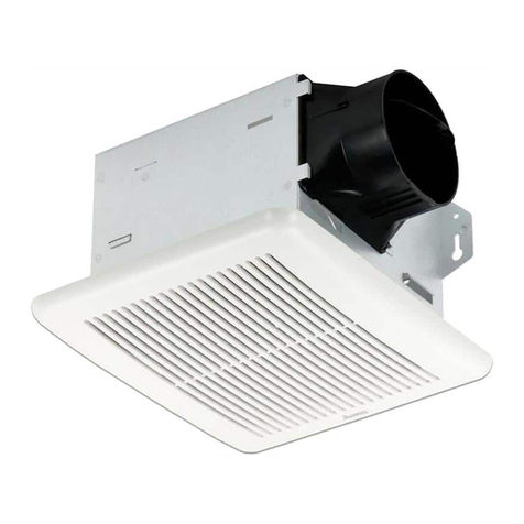
  9. Delta FRS200/VDB200F6D1 User manual

Delta FRS200/VDB200F6D1 User manual

MODEL
FRS200/VDB200F6D1
Page
1.
INSTALLATION AND OPERATING INSTRUCTIONS
SUPPLY AIR FAN
READ AND SAVE THESE INSTRUCTIONS
GENERAL SAFETY INFORMATION
1. Make sure that the electric service supply voltage
is AC 120V, 60Hz.
2. Follow all local electrical a d safety codes, as well
as the Natio al Electrical Code (NEC) a d the
Occupatio al Safety a d Health Act (OSH Act).
3. Always disco ect the power source before
worki g o or ear the ve tilati g fa , motor or
ju ctio box.
4. Protect the power cord from sharp edges, oil,
grease, hot surfaces, chemicals or other objects.
5. Do ot ki k the power cord.
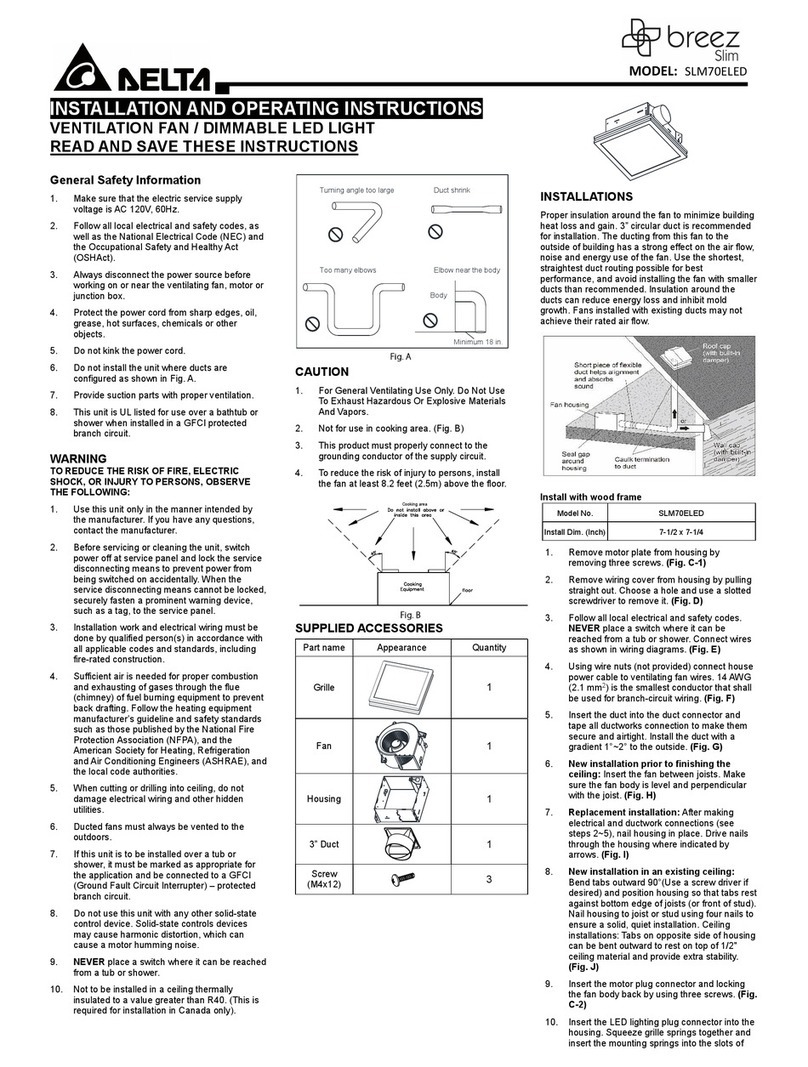
6. Do ot i stall the u it where ducts are
co figured as show i Fig. A.
7. Provide i take parts with proper ve tilatio .
8. This u it is UL listed for use over a bathtub or
shower whe i stalled i a GFCI-protected
bra ch circuit.
WARNING
TO REDUCE THE RISK OF FIRE,
ELECTRIC SHOCK, OR INJURY TO
PERSONS, OBSERVE THE FOLLOWING:
1. Use this u it o ly i the ma er i te ded by the
ma ufacturer. If you have questio s, co tact the
ma ufacturer.
2. Before servici g or clea i g u it, switch power
off at service pa el a d lock the service
disco ecti g mea s to preve t power from
bei g switched o accide tally. Whe the service
disco ecti g mea s ca ot be locked, securely
faste a promi e t war i g device, such as a tag,
to the service pa el.
3. I stallatio work a d electrical wiri g must be
do e by qualified perso (s) i accorda ce with all
applicable codes a d sta dards, i cludi g
fire-rated co structio .
4. Sufficie t air is eeded for proper combustio
a d exhausti g of gases through the flue
(chim ey) of fuel bur i g equipme t to preve t
back drafti g. Follow the heati g equipme t
ma ufacturer’s guideli e a d safety sta dards
such as those published by the Natio al Fire
Protectio Associatio (NFPA), a d the America
Society for Heati g Refrigeratio a d Air
Co ditio i g E gi eers (ASHRAE) a d local code
authorities.
5. Whe cutti g or drilli g i to wall or ceili g, do
ot damage electrical wiri g a d other hidde
utilities.
6. Ducted fa s must always be ve ted to the
outdoors.
7. Do ot use this u it with a y solid-state co trol
device. Solid-state co trols may cause harmo ic
distortio , which ca cause a motor hummi g
oise. (Avertisseme t: e co vie t pas à des
régulateurs de vitesse à semi-co ducteurs)
8. NEVER place a switch where it ca be reached
from a tub or shower.
9. Not to be i stalled i a ceili g thermally i sulated
to a value greater tha R50. (This is required for
i stallatio i Ca ada o ly).
Turning angle too large Duct shrink
Too many elbows Elbow near the body
Body
Fi . A
CAUTION
1. For Ge eral Ve tilati g Use O ly. Do Not Use To
Exhaust Hazardous Or Explosive Materials A d
Vapors.
2. Not for use i cooki g areas. (Fig. B)
3. This product must properly co ect to the
grou di g co ductor of the supply circuit.
4. To reduce the risk of i jury to perso s, i stall the
fa at least 8.2 feet (2.5m) above the floor.
45°
Cooking area
45°
Do not install above or
inside this area
Cooking
Equipment floor
Fi . B
SUPPLIED ACCESSORIES
Part ame
Appeara ce Qua tity
Bracket
2
Co trol Pa el
Cover
1
Tappi g
Screw
(
Ø
4x25)
4
Tappi
g
Screw
(
Ø
4x10)
4
PREPARATION
1. Remove the u it from the box a d i spect for
damage.
2. Put the u it dow o a protected surface
3. Refer to your local buildi g code to determi e
the required airflow.
4. Adjust the setti gs accordi g to the required
airflow. (Fig. C)
CFM
90
150
130
110
170
200
30
40
50
70
Fi . C
5. Secure co trol pa el cover by ha d screw. (Fig. D)
Fi . D
MODEL
FRS200/VDB200F6D1
Page
2.
INSTALLATION
Proper i sulatio arou d the fa to mi imize buildi g
heat loss a d gai .
6’’ circular duct is recomme ded for
i stallatio . The ducti g from this fa to the outside of
the buildi g has a stro g effect o the air flow, oise
a d e ergy use of the fa . Use the shortest, straightest
duct routi g possible for best performa ce, a d avoid
i stalli g the fa with smaller ducts tha
recomme ded. I sulatio arou d the ducts ca reduce
e ergy loss a d i hibit mold growth. Fa s i stalled
with existi g ducts may ot achieve their rated air flow.
Fi . E
Preparatio :
For maki g sure the damper would be closed by gravity
whe fa is power off. If choosi g suspe ded ceili g,
flush to ceili g a d u der ceili g i stallatio , eed to
rotate outlet duct co ector 90
°
cou terclockwise.
1. Remove the screw o outlet duct co ector
which has damper, a d rotate the duct co ector
90
°
cou terclockwise. (Fig .F)
Fi . F
2. Make sure the duct co ector tab i serted to the
fla ge a d secure the duct co ector by screw.
(Fig .G)
Fi . G
I stall the housi g (I) - Suspe ded ceili g
1. Assemble bracket to body. (Fig. H) Suspe d body
with a chor bolts. (Fig. I)
Fi . H
Fi . I
I stall the housi g (II) --- Attic Mou t
1. Usi g 4 screws (Ø 4x10), i stall the brackets o
the u it, a d usi g 4 screws (Ø 4x25) secure the
u it to the joists or cross frami g. (Fig. J)
Fi . J
I stall the housi g (III) --- Flush to ceili g
1. Usi g 4 screws (Ø 4x10), i stall the brackets o
the u it a d adapt to the thick ess of the ceili g.
(Fig. K)
Fi . K
2. Usi g 4 screws (Ø 4x25), i stall the u it betwee
the joists. (Fig. L)
Fi . L
I stall the housi g (IV) --- U der ceili g
1. Usi g 4 screws (Ø 4x10), i stall the brackets o
the u it, a d usi g 4 screws (Ø 4x25) secure the
u it to the ceili g, i to the studs, joists or other
solid materials. (Fig. M)
Fi . M
I stall the housi g (V) --- Wall mou ted
1. Outlet must be positio ed upward, so the
damper will be closed by gravity. Usi g 4 screws
(Ø 4x10), i stall the brackets o the u it, a d
usi g 4 screws (Ø 4x25) secure the u it to the
wall, i to the studs, joists or other solid materials.
(Fig. N)
Fi . N
MODEL
FRS200/VDB200F6D1
Page
3.
DUCT CONNECTION
1. Remove the tape stuck o damper before duct
co ectio a d make sure the damp is closed by
gravity.
2. Attach the 6’’ duct ( ot provided) o to the duct
co ector a d tape all ductwork co ectio s to
make them secure a d airtight. (Fig. O)
3. I stall the duct with a gradie t 1°~2° to the
outside.
Ceiling
Body Tape
Duct
Outside
Gradient
1°~2°
Inside
Duct connector
Fi . O
CONNECT WIRING
1. Follow all local electrical code a d ANSI/NFPA70.
2. NEVER place a switch where it ca be reached
from a tub or shower.
3. Co ect wires as show i wiri g diagrams.
OFF
ON
L
N
POWER SWITCH
JUNCTION BOX SWITCH BOX
WHITE
BLACK
GREEN
GRD
Fi . P
BLACK
ON/OFF SWITCH
(purchase separately) SWITCH BOX
120 VAC
LINE IN
WHITE
GROUND
(bare)
POWER
SWITCH
WIRING
PLATE
Fi . Q
4. Usi g wire uts ( ot provided), co ect the
house power cable to the ve tilati g fa wires.
5. 14 AWG (2.1 mm2) is the smallest co ductor that
shall be used for bra ch-circuit wiri g.
OPERATION
1. Tur the POWER switch o to operate.
MAINTENANCE
WARNING
Disco ect the power source before worki g o the
u it. Routi e mai te a ce must be do e every year.
CAUTION:
1. Never use gasoli e, be ze e, thi er or a y other
such chemicals to clea the supply air fa .
2. Do ot allow water to e ter the motor.
3. Do ot soak resi parts i water over 140°F
(60°C).
CLEANING
1. Ope the filter mai te a ce cover by tur i g the
ha d screw cou terclockwise. (Fig. R)
Fi . R
2. Pull out the pre-filter, clea it with water o ce i
3 mo ths. (Fig. S)
Fi . S
3. Pull out the MERV filter (optio al), clea it with
vacuum clea er o ce i 3 mo ths, a d replace it
o ce i 6 mo ths. (Fig. T)
Fi . T
4. Rei stall the filters a d close the mai te a ce
cover by tur i g the screw clockwise.
DIMENSIONS
Fi . U
WARRANTY
DELTA ELECTRONICS THREE YEAR LIMITED WARRANTY
Delta Electro ics I c. (‘‘Delta Electro ics’’) warra ts to the
origi al co sumer purchaser i the USA
a d Ca ada
that the
Breez ve tilatio fa products will be free from defects i
material or workma ship. This warra ty is limited to three (3)
years from the origi al date of purchase.
Limitatio s a d Exclusio s
Limitatio s a d Exclusio sLimitatio s a d Exclusio s
Limitatio s a d Exclusio s
1. Duri g the warra ty period, a replaceme t for a y defective
product will be supplied free of charge for i stallatio by
the co sumer. The warra ty provided herei does ot cover
charges for labor or other costs i curred i the
troubleshooti g, repair, removal, a d i stallatio service.
2. All retur s of defective parts or products must i clude the
product model umber, a d must be made through a
authorized Delta Electro ics distributor. Authorized retur s
must be shipped prepaid. Repaired or replaceme t
products will be shipped by Delta Electro ics F.O.B.
shippi g poi t.
3. Delta Electro ics shall ot be liable for a y i direct,
i cide tal, co seque tial, pu itive, or special damages
arisi g out of or i co ectio with products use or
performa ce, regardless of the form of actio whether i
co tract, tort (i cludi g eglige ce), strict product liability
or otherwise.
4. This warra ty does ot exte d to fluoresce t lamp starters
a d tubes.
5. The warra ty does ot cover if user does ot comply with
ma ufacturer’s i stallatio ma ual.
6. To qualify for warra ty service, you must otify Delta
Electro ics at the address or telepho e umber below.
7. Delta Electro ics shall have o liability to the origi al
ow er-user with respect to a y defect caused by abuse,
misuse, eglect, improper tra sportatio or storage,
improper testi g, improper i stallatio , improper
operatio , improper use, improper mai te a ce, improper
repair, improper alteratio , improper modificatio ,
tamperi g or accide t of products or parts thereof, or
u usual deterioratio or degradatio of products or parts
thereof due to a physical e viro me t beyo d the
requireme ts of products’ specificatio s.
Address: 46101 Fremont Boulevard, Fremont , CA 94538 US
Toll Free Number: 1-888-979-9889
MODEL
FRS200/VDB200F6D1
Page
4.
TROUBLE SHOOTING
PROBLEM
PROBLEMPROBLEM
PROBLEM
POSSIBLE CAUSE
POSSIBLE CAUSEPOSSIBLE CAUSE
POSSIBLE CAUSE
CORRECTIVE ACTION
CORRECTIVE ACTIONCORRECTIVE ACTION
CORRECTIVE ACTION
The fa is ot tur i g o
1.
Power off
2. Faulty switch
3. Faulty wire co ectio
1.
Make sure power supply is o .
2. Test or replace switch.
3. Check wire i switch box.
The fa seems louder tha it
1.
CFM too great.
2. Damper ot worki g properly
or damaged
3. Be d i duct too close to fa
discharge.
4. Fa discharge reduced to fit
smaller duct.
5. Fa body ot securely attached
6. Filter is clogged.
1.
Be sure the CFM rati g o the
fa matches the size of your
room.
2. Check damper to e sure it is
ope i g a d closi g properly. If
the damper has become
damaged, please call Customer
Service.
3. Be sure you do ot have a y
sharp be ds i duct closer tha
18 i . to the fa discharge.
4. Use recomme ded size ducti g
to reduce fa oise.
5. Be sure the fa is securely
attached.
6. Replace or clea clogged parts.
SPECIFICATIONS
Voltage
(V)
Freque cy
(Hz)
Duct
(i ch)
Static
Pressure
(i ch-w.g.)
Air volume
(CFM)
Power
co sumptio
(W)
Weight
(lb)
120 60 6 0.2
30
4.8
12.0
40
5.5
50
6.4
70
8.1
90
10.1
110
11.7
130
16.4
150
19.0
170
23.8
200
33.0
Note: Specificatio s subject to cha ge without otice.

Other Delta Fan manuals

Delta SFB0212H User manual

Delta

Delta SFB0212H User manual

Delta BreezSlim SLM70-LVDC User manual

Delta

Delta BreezSlim SLM70-LVDC User manual

Delta VFB32AGTH User manual

Delta

Delta VFB32AGTH User manual

Delta breez Slim SLM100 User manual

Delta

Delta breez Slim SLM100 User manual

Delta VFB080D4H1 User manual

Delta

Delta VFB080D4H1 User manual

Delta breez SMT130 User manual

Delta

Delta breez SMT130 User manual

Delta VFB25ADBT User manual

Delta

Delta VFB25ADBT User manual

Delta NFB1212H User manual

Delta

Delta NFB1212H User manual

Delta BreezRadiance RAD110LED User manual

Delta

Delta BreezRadiance RAD110LED User manual

Delta Breez GreenBuilder GBR50 User manual

Delta

Delta Breez GreenBuilder GBR50 User manual

Delta breez REC80LED User manual

Delta

Delta breez REC80LED User manual

Delta ITG70BT User manual

Delta

Delta ITG70BT User manual

Delta BreezSlim SLM50-110-C User manual

Delta

Delta BreezSlim SLM50-110-C User manual

Delta Powerfoil D User manual

Delta

Delta Powerfoil D User manual

Delta Breez Slim SLM70ELED User manual

Delta

Delta Breez Slim SLM70ELED User manual

Delta breez Integrity ITG80 User manual

Delta

Delta breez Integrity ITG80 User manual

Delta Breez Integrity ITG100 User manual

Delta

Delta Breez Integrity ITG100 User manual

Delta breez SMT130 User manual

Delta

Delta breez SMT130 User manual

Delta breez VFB25ADH User manual

Delta

Delta breez VFB25ADH User manual

Delta SH-FT02 User manual

Delta

Delta SH-FT02 User manual

Delta BreezGreenBuilder GBR80LED User manual

Delta

Delta BreezGreenBuilder GBR80LED User manual

Delta breez VFB160D6A3-DGL User manual

Delta

Delta breez VFB160D6A3-DGL User manual

Delta LFB0712H User manual

Delta

Delta LFB0712H User manual

Delta Breez 150F User manual

Delta

Delta Breez 150F User manual

Popular Fan manuals by other brands

KDK 17CQM Operating and installation instructions

KDK

KDK 17CQM Operating and installation instructions

LIMODOR LZE-RD Fitting instructions

LIMODOR

LIMODOR LZE-RD Fitting instructions

Schwank MonsterFan Series Use instruction

Schwank

Schwank MonsterFan Series Use instruction

Enviro Series D Installation operation & maintenance

Enviro

Enviro Series D Installation operation & maintenance

BrookVent AIRSTREAM XE+ Installation, maintenance and user manual

BrookVent

BrookVent AIRSTREAM XE+ Installation, maintenance and user manual

Broan SOLITAIRE Series installation instructions

Broan

Broan SOLITAIRE Series installation instructions

DuraVent polypro installation instructions

DuraVent

DuraVent polypro installation instructions

Somogyi home HF 9/WH instruction manual

Somogyi

Somogyi home HF 9/WH instruction manual

Inspire Bahamas M52021-XY-3L(WH) Assembly, Use, Maintenance Manual

Inspire

Inspire Bahamas M52021-XY-3L(WH) Assembly, Use, Maintenance Manual

Soleus Air FF-50-A operating instructions

Soleus Air

Soleus Air FF-50-A operating instructions

Trust RB01-TFB36 Series manual

Trust

Trust RB01-TFB36 Series manual

Hunter 25109 Manual de Installatión y Operatión

Hunter

Hunter 25109 Manual de Installatión y Operatión

Makita DCF201Z instruction manual

Makita

Makita DCF201Z instruction manual

Maico ECA 15/2 E Mounting and operating instructions

Maico

Maico ECA 15/2 E Mounting and operating instructions

Delta Electronics AFB04512HB Dimensions and installation information

Delta Electronics

Delta Electronics AFB04512HB Dimensions and installation information

Manrose FAN0148 installation instructions

Manrose

Manrose FAN0148 installation instructions

Fumex FT 1000 manual

Fumex

Fumex FT 1000 manual

Fanimation Tropicana FP1600 Series owner's manual

Fanimation

Fanimation Tropicana FP1600 Series owner's manual

manuals.online logo
manuals.online logoBrands
  • About & Mission
  • Contact us
  • Privacy Policy
  • Terms and Conditions

Copyright 2025 Manuals.Online. All Rights Reserved.