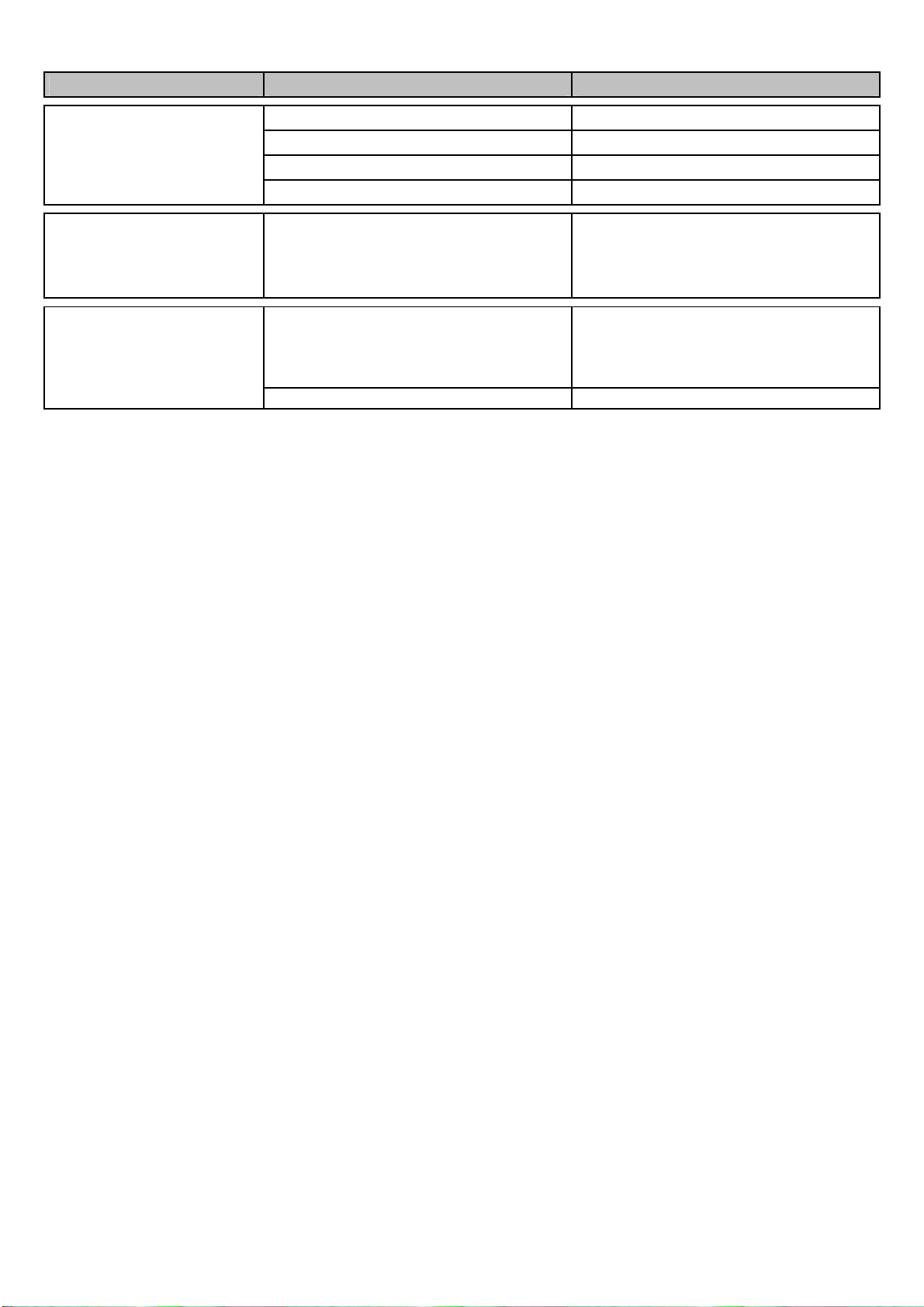
Deltec SC 2060 User manual

®
SC 2060- SC 4580
Bedienungsanleitung
Seite 2
Ersatzteilliste
Seite 8
Operating instruction
Page 10
Spare part list
Page16
Istruzioni d’uso
pagina 18
e parti di ricambio
pagina 24
нструкция по эксплуатации
Страница 26
Список запчастей
Страница 34

Wichtige Sicherheitshinweise
Warnung: Zum Schutz vor Verletzungen sollten grundlegende Vorsichtsmaßnahmen und folgende
Sicherheitshinweise beachtet werden.
1) Sicherheitshinweise Lesen und befolgen
) Gefahr: Zur Vermeidung eines elektrischen Schlages sollten alle Aquarium Geräte mit Vorsicht
gehandhabt werden. In keinem der unten aufgeführten Fälle sollte die Reparatur vom Kunden
versucht werden. Das Gerät muss zu einem autorisierten Kundendienst gebracht werden.
a. Ein Gerät mit beschädigtem Kabel oder Stecker darf nicht in Betrieb genommen werden. Das
gleiche gilt, wenn das Gerät nicht richtig funktioniert, fallen gelassen oder anderweitig
beschädigt wurde.
b. Um ein Nasswerden des Gerätesteckers oder der Steckdose zu vermeiden, sollten der
Aquarium Unterschrank und das Becken seitlich von der Wandsteckdose aufgestellt werden.
Somit können keine Tropfen auf den Stecker oder die Steckdose fallen. Eine „Tropfenschleife“
sollte in jedem Kabel zwischen Aquarium und Steckdose vorgesehen werden. Die
„Tropfenschleife“ ist der Teil des Kabels, der unter der Steckdose durchhängt (Skizze 1). Auf
diese Weise tropft das Wasser unter der Steckdose vom Kabel ab und kann nicht mit dieser in
Berührung kommen. Wenn der Stecker oder die Steckdose nass wird, NICHT das Kabel
herausziehen, sondern die Stromversorgung an der Sicherung bzw. am Leistungsschalter
trennen. Dann erst den Stecker herausziehen und prüfen, ob sich Wasser in der Steckdose
befindet.
3) Kinder müssen beaufsichtigt werden, wenn Sie sich am Aquarium oder in dessen Nähe
Aufhalten.
4) Bei Nichtverwendung, vor dem Montieren/Demontieren von Teilen oder vor dem Reinigen
müssen die betroffenen Geräte stets ausgesteckt werden. Nicht am Kabel ziehen. Zum
Herausziehen des Kabels immer den Stecker greifen.
5) Die Geräte dürfen nur für den vorgesehenen Zweck verwendet werden. Die Verwendung von
Zubehör, das vom Hersteller nicht empfohlen oder verkauft wird, kann gefährliche
Bedingungen verursachen.
6) Das Gerät nicht an einer Stelle installieren oder lagern, wo es der Witterung oder
Temperaturen unter null Grad ausgesetzt ist.
7)
Das Gerät ist mit einem Schukostecker ausgestattet. Dieser Stecker darf auf keine Weise
verändert oder umgangen werden.
Wird der Stecker entfernt erlischt jeder Garantieanspruch!
Diese Anleitung aufbewahren
- -

Innenabschäumer SC 2060 – SC 4580
Die Abschäumer der Serie SC sind für den Betrieb in externen Filterwannen bestimmt
(Zeichnung a). Kennzeichnend ist die sehr hohe Abschäumleistung bei kompakter Bauweise
und sehr niedrigem Energieverbrauch. Die Abschäumer werden unter anderem mit einem
Schaumtopfentleerungsschlauch, einem Schalldämpfer, der zum Reinigen zerlegt werden
kann, sowie einem Präzisions- Niveauregler geliefert.
Einbau
Der Wasserstand in der Filterwanne sollte zwischen 180 - 90 mm sein. Die Abschäumer
dieser Bauart reagieren empfindlich auf einen schwankenden Wasserstand. Die
Vorraussetzung für einen einwandfreien und zuverlässigen Betrieb ist ein konstanter
Wasserstand in der Filterwanne.
Dadurch, dass die Abschäumerpumpe(n) Wasser aus der Filterwanne mit einem bestimmten
Niveau gegen die Wassersäule im Abschäumer pumpen muss, ändern sich die
Pumpenwerte wie Luftleistung, Stromaufnahme, Durchflussmenge bei unterschiedlichen
Wasserständen (siehe technische Daten).
Um jederzeit einen konstanten Wasserstand in der Filterwanne zu garantieren, wird
empfohlen, ein Nachfüllsystem wie den Deltec Aquastat 1000 oder ähnliches zu verwenden.
Eine andere Möglichkeit ist der Einbau einer Abschäumerkammer (Zeichnung b) in die
Filterwanne, die einen höheren Wasserstandstand als die Filterwanne haben muss. Vom
Aquairumüberlauf oder der Hauptpumpe kann diese Abschäumerkammer über einen Bypass
mit Wasser versorgt werden. Die Höhe der Abschäumerkammer sollte zwischen 180 und
90 mm sein.
-3-

Höhe min. 180mm max. 290mm *
* Es ist empfehlenswert ie max. Höhe zu wählen
Inbetriebnahme
Nach dem Einbau sollte der Abschäumer wie folgt in Betreib genommen werden:
-Niveauregler (Zeichnung c) durch Drehen gegen den Uhrzeigersinn ganz öffnen.
-Wasserzufuhr für die Abschäumerkammer einschalten (falls vorhanden).
-Wasserstand in dem Bereich Oberkante Bajonett – Unterkante Schaumtopf einstellen
(Zeichnung d).
-Niveauregler langsam schließen bis Schaum im unteren Bereich des Schaumtopfrohres
sichtbar ist.
-Um ein anfängliches Überschäumen zu vermeiden, die Schaumsäule mittels des
Niveaureglers zunächst eher niedriger einstellen
-Die Schaumbildung nach der Inbetriebnahme beobachten und eventuell mit dem
Niveauregler korrigieren.
Eine endgültige Feineinstellung kann frühestens nach 4 Stunden vorgenommen werden.
Dazu wird mit dem Niveauregler das Schaumbild im Steigrohr so eingestellt, dass die feinen
Luftblasen leicht über dem Schaumtopfboden anfangen zu größeren Blasen zu zerplatzen
(Zeichnung d).
-Für nassen Schaum (helle Flüssigkeit im Schaumtopf) den Niveauregler eindrehen.
-
Für trockenen Schaum (dunkle Flüssigkeit im Schaumtopf) den Niveauregler
herausdrehen.
-4-

c) Niveauregler d) Schaumtopf mit Übergangsrohr
Betrieb mit Ozon
Die Abschäumer können bis max. 50 mg/Std. Ozon pro Pumpe betrieben werden. Dazu
wird ein Anschluss des Ozongerätes (mit einem Silikonschlauch) mit dem Luftschlauch der
Abschäumerpumpe verbunden. Die Luft wird selbsttätig angesaugt. Bei Leistungsabfall
sollte das Ozongerät auf Verunreinigungen nachgesehen werden.
Frisches Meerwasser
Durch bestimmte Zusätze in vielen Meersalzen erzeugt der Abschäumer extrem feine
Luftblasen, die nicht zurückgehalten werden können, gleichzeitig wird sehr wässeriger
Schaum erzeugt. Durch häufiges Entleeren des Schaumtopfes, können die besagten
Inhaltsstoffe im Aquariumwasser reduziert werden. Außerdem kann durch vorübergehendes
stärkeres Füttern die extreme Feinblasenbildung vermindert werden.
Technische Daten
Maße
mm
Aquariengröße
Liter
Wasserstand
mm
Stromaufnahme
Watt
Luft
Liter/Std.
Anschlüsse
Ø mm
Technische
Daten
S Serie Stellfläche
Höhe
Hoher
Besatz
Normaler
Besatz min. max. min. max. min. max. Ablauf
S 2060 280x220 600 1400 1700 180 260 25 28 1100 1300 50
S 2560 270x320 600 2000 2400 180 260 29 31 1500 1600 50
S 3070 320x360 700 4000 4800 180 260 58 61 3000 3200 50
S 3070S 320x360 650 5000 6000 180 260 70 76 3200 3500 50
S 4080 420x470 800 7500 9000 220 290 117 5100 63
S 4580 475x525 800 10000 13000 220 290 156 6800 63
-5-

Fehlersuche
Symptom Ursache Maßnahme
Luftzuleitung zur Pumpe verstopft reinigen
Ozongerät verschmutzt reinigen
Luftschlauch abgeknickt Schlauchführung ändern
Luftansaugdüse verstopft reinigen
Pumpe läuft, jedoch
keine oder zu
geringe Luftmenge
Strömungsklappe(n) in Pumpe fest reinigen
Kommt bei bestimmten Seesalzen
und bei Zugabe von Wasser-
aufbereitungsmitteln vor
Andere Salze verwenden, mehr
füttern
Starke Luftperlung
im Ablaufwasser Bei sehr starker Wasser-Belastung
nach Neueinrichtung mit lebenden
Steinen
Luftmenge stark drosseln
Wird die Pumpe (nach
Inbetriebnahme) trocken gelagert,
kann das Lager in der vorderen
Lagerplatte eintrocknen.
Laufeinheit wie nachstehend
illustriert ausbauen und in
Leitungswasser durch axiale und
radiale Bewegungen lösen
Pumpe läuft nicht an
Laufeinheit falsch montiert Siehe Ein- Ausbau der Laufeinheit
Wartung
Bei korrektem Einbau und Einstellung benötigen Deltec Abschäumer denkbar wenig
Wartung. Durch Kalkwassermischer und Kalkreaktoren kann es jedoch zu Kalkablagerungen
in der Pumpe kommen, die zu Funktionsstörungen führen können.
Es wird empfohlen bei Störungen oder alle 6 Monate den Rotor sowie die Strömungsklappen
auf Leichtgängigkeit und die Lufteinzugsdüse auf freien Durchgang hin zu prüfen. Durch
eintauchen der Teile in einen handelsüblichen Entkalker lösen sich die Kalkablagerungen.
Ein frühzeitiges Verstopfen der Lufteinzugsdüse durch Luftstaub und Salzkristalle kann
durch ca. 15-30 minütiges Abstellen der Pumpe 1 mal pro Woche vermieden werden.
Zu beachten: Um einen störungsfreien Betrieb zu gewährleisten, ist es wichtig den
Niveauregler in regelmäßigen Abständen (min. einmal wöchentlich) auf Verunreinigungen zu
kontrollieren und gegebenenfalls zu reinigen. Dazu kann der Niveauregler nach oben
herausgezogen werden. Nach wiedereinsetzen des Niveaureglers ist der Wasserstand im
Abschäumer zu kontrollieren und ggf. neu einzustellen. Verunreinigungen und Ablagerungen
können zur Erhöhung des Wasserstandes bis hin zum Überlaufen des Abschäumers führen.
Ein- un Ausbau er Laufeinheit
Es ist darauf zu achten die Laufeinheit nur mit dem mitgelieferten Extrakter (Bild 1) ein-
oder auszubauen. Da die Laufeinheit durch seinen Magneten stark in den Stator gezogen
wird, kann es beim unkontrollierten herein ziehen zu Beschädigungen des Nadelrades oder
zum Bruch der Keramikwelle kommen.
Der Aus- bzw. Einbau der Laufeinheit sollte wie folgt geschehen:
-lösen der Verschraubung an der Saugseite (Bild 1)
-Aufschrauben des Extraktors auf das Gewinde der Laufeinheit (Bild )
-Herausziehen der Laufeinheit (Bild3)
-Beim Einbau ist darauf zu achten, dass die Zentrierung der Laufeinheit in die
Führungsschiene des Stator gesteckt wird (Bild4). Achtung: Starke Magnetkräfte.
-Die Laufeinheit wird durch einen O-Ring im Stator fixiert. Den Rotor deshalb die letzten
ca. mm kräftig in den Stator drücken damit der O-Ring zur Fixierung in die Statornut
einrastet.
-6-

Bil 1 Bil 2
Bil 3 Bil 4
-7-

Ersatzteilliste
-8-

SC2060 SC2560 SC3070 SC3070S
SC4075 SC4580
Bezeichnung Art. Nr. Art. Nr. Art. Nr. Art. Nr. Art. Nr. Art. Nr.
A Pumpe mit Verrohrung 80002000
80003000
80004000
80005000
80006000
80007000
1 Grundgerät 81201000
81251000
81301000
81351000
81401000
81451000
2 Siebplatte 80202000
80252000
80302000
80352000
80340000
80345000
3 Schaumtopf 80203000
80253000
80303000
80353000
80403000
80453000
4 Schaumtopf Deckel 80204000
80254000
80304000
80354000
80404000
80454000
5 O-Ring Schaumtopf 80500110
80500139
80500160
80500200
80500200
80500250
6 Stator 80010000
80011000
80011000
80011000
80011000
80011000
7 Rotor 80014000
80015000
80015000
80015000
80015000
80015000
8 O-Ring Pumpe 80016000
80016000
80016000
80016000
80016000
80016000
9 Lagerplatte 80017000
80017000
80017000
80017000
80017000
80017000
10
Überwurf Pumpe 80018000
80018000
80018000
80018000
80018000
80018000
11
Luftansaugdüse 81209000
81259000
81309000
81359000
81409000
81459000
12
Extrakter 80020000
80020000
80020000
80020000
80020000
80020000
13
Schalldämpfer 1 80205000
80205000
80205000
81205000
81205000
81205000
14
Schalldämpfer 2 80206000
80206000
80206000
81206000
81206000
81206000
15
Silikonschlauch 1Meter 61770000
61770000
61770000
61770000
61770000
61770000
16
Niveauregler 80207000
80207000
80207000
80207000
80407000
80407000
17
O-Ring 16 xxx 93040400
93040400
93040400
93040400
93040400
18
Ablaufnippel xxx 80258000
80258000
80258000
80258000
80258000
19
Überwurfmutter 16 xxx 93040100
93040100
93040100
93040100
93040100
20
Kugelhahn 12 93419000
93419000
93419000
93419000
93419000
93419000
21
Diffusor 80207000
80207000
80207000
80207000
80207000
80207000
22
O-Ring Rotor 80019000
80019000
80019000
80019000
80019000
80019000
-9-

IMPORTNT SAFETY INSTRUCTIONS
WARNING To guard against injury, basic safety precautions should be observed, including the
following.
1)
READ AND FOLLOW ALL SAFETY INSTRUCTIONS.
)
DANGER – To avoid possible electric shock, special care should be taken since water is
employed in the use of aquarium equipment. For each of the following situations, do not
attempt repairs by yourself; return the appliance to an authorized service facility for service
or discard the appliance.
a)
Do not operate any appliance if it has a damaged cord or plug, or if it is malfunctioning or
has been dropped or damaged in any manner.
b)
To avoid the possibility of the appliance plug or receptacle getting wet, position aquarium
stand and tank to one side of a wall-mounted receptacle to prevent water from dripping
onto the receptacle or plug.
A “drip-loop”, shown in the figure below, should be arranged by the user for each cord
connecting an aquarium appliance to a receptacle. The “drip-loop” is that part of the cord
below the level of the receptacle, or the connector if an extension cord is used, to prevent
water travelling along the cord and coming in contact with the receptacle.
If the plug or socket does get wet, DON´T unplug the cord. Disconnect the fuse or circuit
breaker that supplies power to the appliance. Then unplug and examine for presence of
water in the receptacle.
3)
Close supervision is necessary when any appliance is used by or near children.
4)
Do not use an appliance for other than intended use. The use of attachments not
recommended or sold by the appliance manufacturer may cause an unsafe condition.
5)
Make sure an appliance mounted on a tank is securely installed before operating it.
6)
Read and observe all the important notices on the appliance.
7)
If an extension cord is necessary, a cord with a proper rating should be used. A cord rated for
less amperes or watts than the appliance rating may overheat. Care should bee taken to
arrange the cord so that it will not be tripped over or pulled.
8)
This appliance has a polarized plug (one blade is wider than the other). As safety feature, this
plug will fit in a polarized outlet only one way. If the plug does not fit, contact a qualified
electrician. Never use with an extension cord unless plug can be fully inserted. Do not attempt
to defeat this safety feature.
Exception: This instruction may be omitted for an appliance that is not provided with a
polarized attachment plug.
Removing of the plug invalidates the warranty!
SAVE THESE INSTRUCTIONS
-10-

Protein Skimmer SC 2060 – SC 4580
Deltec ”SC“ series protein Skimmer are very compact, highly efficient and are fitted with a
special low energy skimmer pump.
The “SC” skimmers features
-precision waterlevel adjuster
-remote skimmer cup drain
-silencer (the silencer can be opened for cleaning)
-designed to operate in external filtersumps (diagram a)
Installation
For best performance the water level in the filter sump should be between 180 and
90 mm. Protein skimmers of this design are very sensitive to any water level changes.
A prerequisite for continuous efficient performance is a constant water level in which the
skimmer operates. Ideally, a water level top up system should be used such as the Deltec
Aquastat 1000 or better still a separate skimmer compartment in the sump (diagram b).
The water level in the skimmer compartment should be higher than in the rest of the sump.
but within the levels recommended for the skimmer model.
This compartment can be supplied with water from a bypass of the aquarium overflow.
-11-

Height of skimmer compartment
between 180 -290mm
Starting the skimmer
-position the skimmer in the sump
-feed water into the skimmer compartment (if applicable)
-open the water level adjuster (diagram c) fully by turning it anti-clockwise
-start the skimmer pump
-close the water level adjuster until fine bubbles are visible between the bayonet and
the bottom of the skimmer cup (diagram d)
-initially keep the foam level in the skimmer cup low to avoid over skimming and
possible flooding of the cup
-wait a minimum of 4 hours before the final adjustment
-turn the water level adjuster in or out until the fine air bubbles start bursting
approximately half way up the cups riser tube
-for dry foam turn the water level adjuster anti-clockwise
-for wet foam clockwise
-Important:
Never allow the pump to run dry.
Operation with Ozone
The Skimmer can be operated with ozone up to max. 50 mg/h per pump. One air
connection of the ozoniser should be connected via a suitable silicon hose to the protein
skimmer pump. The air is automatically sucked in the ozoniser by the skimmer pump.
Should the skimmer performance deteriorate please check the ozoniser for blockage.
-1 -

c) Water level adjuster d) Skimmer cup
Fresh salt water
If the skimmer is used with new water on an aquarium it is common for find an excessive
quantity of small bubbles and often the skimmer cup fills with a clear liquid. This is due to
the high surface tension of the new water which prevents the bubbles from bursting. Once
the water matures this effect will go away but can take up to -3 weeks. The effect is
different on different salt brands and is often dependant on levels of conditioning agents
added to the salt. Once these are skimmed out then the skimmer will act normally.
Heavier feeding in the initial stages will give the chemically pure water something to react
with and allow it to mature into proper aquarium salt water rather than the initial chemical
soup which is new salt water.
Technical ata
Dimensions
mm
Aquarium size
litre
Water level
required hight*
mm
Power
consumption
Watt
Air
litre/h
onnections
Ø mm
technical
data
S Serie Footprint
height
high
stocking
normal
stocking
min. max. min. max. min. max. Outlet
S 2060 280x220
600 1400 1700 180 260 25 28 1100 1300 50
S 2560 270x320
600 2000 2400 180 260 29 31 1500 1600 50
S 3070 320x360
700 4000 4800 180 260 58 61 3000 3200 50
S 3070S 320x360
650 5000 6000 180 260 70 76 3200 3500 50
S 4080 420x470
800 7500 9000 220 290 117 5100 63
S 4580 475x525
800 10000 13000 220 290 156 6800 63
* it is best to chose the max. water level
-13-

Fault fin ing
malfunction cause remedy
silencer, airline or venturi blocked
clean
airline kinked remove kink
ozonizer blocked clean
Pump produces
insufficient air
Pump flaps blocked clean
excessive air bubbles in
aquarium water
caused by additives in certain sea
salts and water conditioners
Use different salt or feed heavily
for a period, empty skimmer cup
frequently. This condition may
last for several weeks.
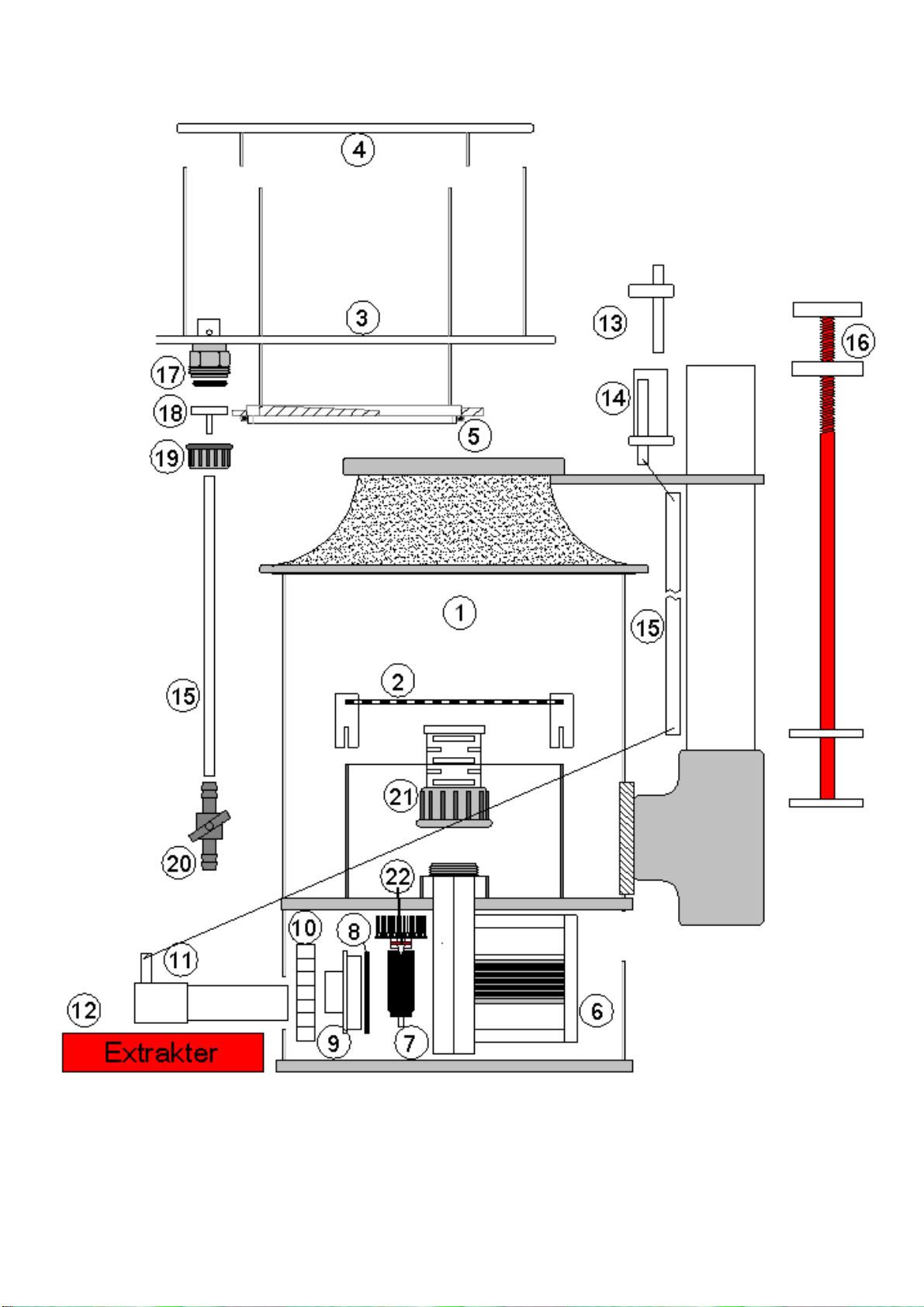
Front bearing of the impeller stuck.
When the pump (after having been
used) has been stored dry for a period
of time, the front bearing can "dry out".
Remove impeller with the extractor tool
as illustrated and loosen the bearing by
moving the bearing plate around and
along the ceramic shaft in tap water.
Pump does not start
Impeller incorrectly fitted See service hints
Maintenance
The Deltec skimmer range should need very little adjustment and maintenance once set
correctly however due to the high levels of calcium in marine aquariums it is common for
deposits to build up on moving parts requiring periodical cleaning. Deltec pumps are fitted
with little flaps inside the outlet of the pump and inside the housing, which flip from one
side to the other depending on the direction of rotation thus ensuring that the pump always
operates at full duty. It is recommended every 6 months, or when required, that the pumps
are removed from the skimmer having first drained the body of Water.
Check and clean the impellor of debris. Ensure that the direction flaps move easily and if
necessary soak the neck of the pump housing in white vinegar or lime scale remover to
dissolve any calcium carbonate deposits. A build up of calcium, dust and salt can restrict or
block the venturi inlet on the connecting pipe work and reduce the skimming efficiency. This
should be checked and carefully cleaned with a toothpick or fine drill rotated between the
fingertips.
It is advisable to stop the pump for approximately 15 minutes once every week in order to
dissolve any dust or salt crystals that may have collected in the venture tube.
Please observe: The water level adjuster must be checked at regular intervals (at least
once a week) for accumulation of dirt or other substances with may inhibit or interfere with
its proper function. If required please clean. For this purpose the water level adjuster can be
simply removed by pulling it upwards. After reinstallation of the water level adjuster please
make sure it is correctly set. Any foreign bodies, limestone build up ect. can cause the
skimmer water level to raise, in extreme cases the skimmer may get flooded.
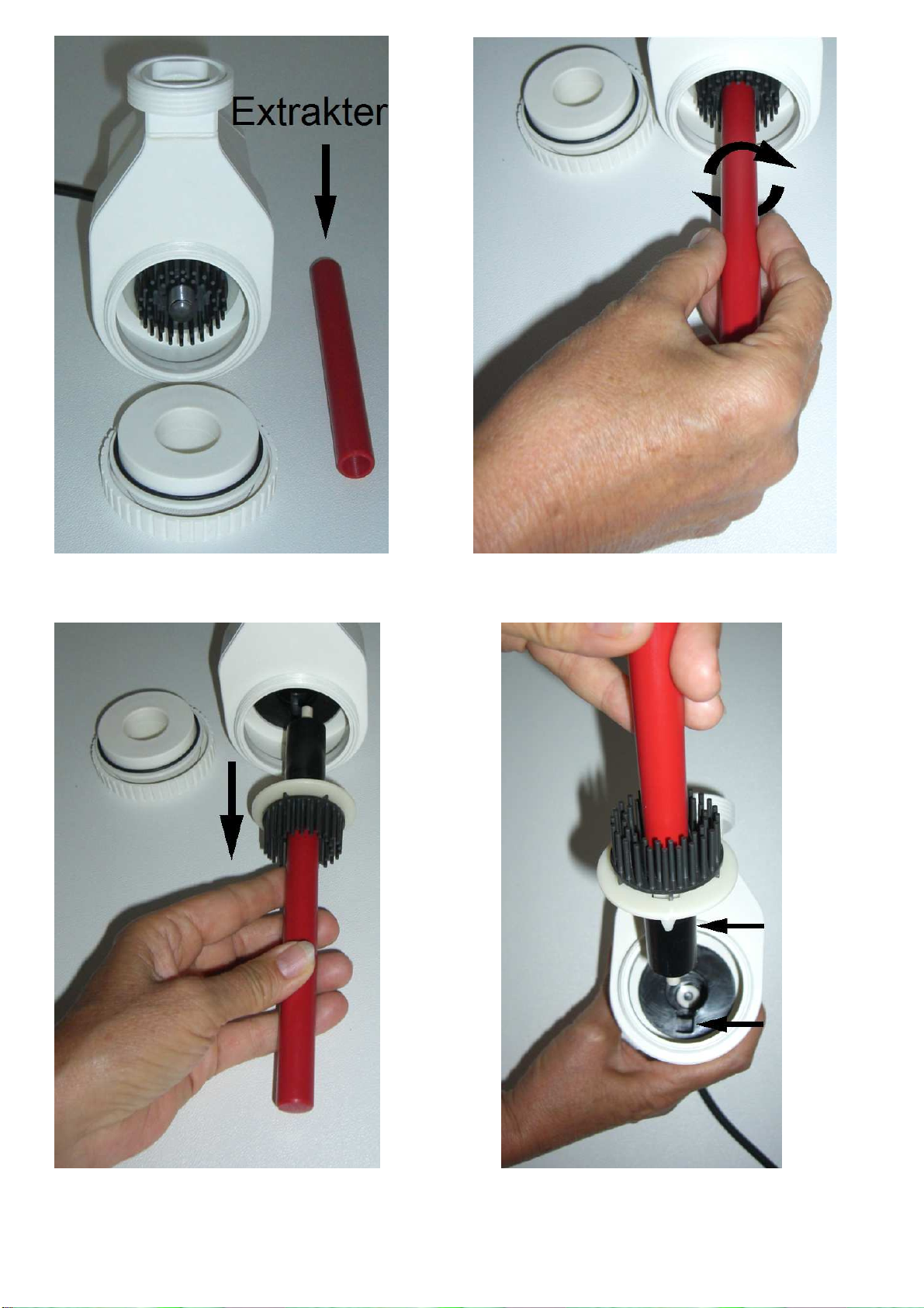
Service hints
The skimmer pump is fitted with a very powerful rotor magnet. To remove the rotor from
the pump use only the special extractor tool (picture 1). Screw the extractor onto the
rotor’s centre piece (picture ) and pull the rotor out of the pumps housing slowly and
deliberately in a straight line (picture 3). Be careful not to put any side forces onto the
ceramic rotor shaft as this might brake the hard and brittle material.
Use the same tool when inserting the rotor into the pump housing.
Make sure that the guide fitted to the bearing plate is located in the slot of the stator
(picture 4). The Impeller is fixed inside the stator by an o-ring. It requires a certain
pressure to push the impeller the last -3mm into its correct position.
-14-

Picture 1 Picture 2
Picture 3 Picture 4
-15-

Spare part list
-16-

SC2060 SC2560 SC3070 SC3070S
SC4080 SC4580
Description Art. No. Art. No. Art. No. Art. No. Art. No. Art. No.
A Skimmer pump incl. piping
80002000
80003000
80004000
80005000
80006000
80007000
1 Body only 81201000
81251000
81301000
81351000
81401000
81451000
2 Strainer 80202000
80252000
80302000
80352000
80340000
80345000
3 Skimmer cup 80203000
80253000
80303000
80353000
80403000
80453000
4 Skimmer cup lid 80204000
80254000
80304000
80354000
80404000
80454000
5 O-Ring skimmer cup 80500110
80500139
80500160
80500200
80500200
80500250
6 Stator 80010000
80011000
80011000
80011000
80011000
80011000
7 Needle wheel 80014000
80015000
80015000
80015000
80015000
80015000
8 O-ring pump 80016000
80016000
80016000
80016000
80016000
80016000
9 Bearing plate 80017000
80017000
80017000
80017000
80017000
80017000
10
Cap nut pump 80018000
80018000
80018000
80018000
80018000
80018000
11
Air inlet adapter 81209000
81259000
81309000
81359000
81409000
81459000
12
Extractor 80020000
80020000
80020000
80020000
80020000
80020000
13
Silencer 1 80205000
80205000
80205000
81205000
81205000
81205000
14
Silencer 2 80206000
80206000
80206000
81206000
81206000
81206000
15
Silicone hose 1 meter 61770000
61770000
61770000
61770000
61770000
61770000
16
Water level adjuster 80207000
80207000
80207000
80207000
80407000
80407000
17
O-Ring 16 xxx 93040400
93040400
93040400
93040400
93040400
18
Skimmer outlet xxx 80258000
80258000
80258000
80258000
80258000
19
Cap nut 16 xxx 93040100
93040100
93040100
93040100
93040100
20
Shut-off- valve 93419000
93419000
93419000
93419000
93419000
93419000
21
Diffuser 80207000
80207000
80207000
80207000
80207000
80207000
22
O-Ring Rotor 80019000
80019000
80019000
80019000
80019000
80019000
-17-

NORME DI SICUREZZA
AVVERTENZA: Per evitare incidenti si raccomanda di osservare le norme generali di sicurezza, tra
cui le seguenti:
1) LEGGERE E SEGUIRE SCRUPOLOSAMENTE TUTTE LE NORME DI SICUREZZA.
) PERICOLO – Considerato che l’uso di attrezzature per acquario avviene in presenza di acqua,
agire sempre con particolare cautela per evitare scosse elettriche. Per ognuna delle seguenti
situazioni possibili, si raccomanda di non tentare di eseguire da sé eventuali riparazioni, ma di
portare l’apparecchio presso un centro assistenza autorizzato o provvedere alla sua
rottamazione.
a. Non mettere in funzione l’apparecchio se il cavo d’alimentazione o la spina appaiono
danneggiati, se l’apparecchio è malfunzionante, se è caduto o ha subito un qualsiasi danno.
b. Per evitare il gocciolamento dell’acqua sulla presa o sulla spina, posizionare l’acquario e il
mobile di fianco alla presa montata a parete in modo che questa resti visibile.
Si raccomanda di fare eseguire al cavo una curva “anti-gocciolamento” come mostrato nella
figura sottostante. Eseguire l’operazione per tutti i componenti elettrici dell’acquario. In
questo modo una parte di cavo si trova sotto il livello della presa, o della spina di
collegamento nel caso si usi una prolunga, impedendo così che l’acqua gocciolando lungo il
cavo venga a contatto con la presa.
Se la presa o la spina si bagna, NON disinserire il cavo, ma scollegare l’interruttore generale
che porta corrente all’apparecchio. Quindi scollegare la spina e verificare la presenza di
acqua all’interno della presa.
3) Se l’apparecchio viene utilizzato da o in presenza di bambini, è necessaria un’attenta
supervisione da parte degli adulti.
4) Non utilizzare l’apparecchio per usi diversi da quelli a cui è destinato. L’uso di accessori non
raccomandati o non venduti dal produttore dell’apparecchio possono essere causa di
condizioni di funzionamento non sicure.
5) Assicurarsi che gli apparecchi montati sull’acquario siano correttamente installati prima di
avviarli.
6) Leggere ed osservare tutte le informazioni importanti sull’apparecchio.
7) Se è necessario l’uso di una prolunga, assicurarsi che il cavo sia adatto al voltaggio utilizzato.
Se il cavo è messo a punto per meno ampere or watt rispetto all’apparecchio, potrebbe
surriscaldarsi. Fare attenzione che il cavo non sia troppo teso o schiacciato.
8) (Solo per UK) Questo apparecchio è dotato di spina polarizzata (uno spinotto è più largo
dell’altro). Come misura di sicurezza, tale spina potrà essere inserita in un solo modo in una
presa polarizzata. Se la spina non è adatta, rivolgersi ad un elettricista qualificato. Non
utilizzare una prolunga se la spina non si inserisce completamente. Non tentare di eludere
questa condizione di sicurezza.
Eccezione: Questa avvertenza può essere omessa se l’apparecchio non è dotato di spina
polarizzata.
In caso i manomissione ella spina eca e ogni garanzia!
“CONSERVATE LE PRESENTI ISTRUZIONI”
-18-

Schiumatoio interno SC 2060 – SC 4580
Gli schiumatoi della serie SC, ideati per funzionare in una sump esterna (disegno a), sono
compatti e molto efficienti, caratterizzati da un’alta resa ed un basso consumo energetico.
Sono dotati di regolatore di livello ad alta precisione, tubo per lo svuotamento del bicchiere
e silenziatore che può essere smontato per la pulizia.
Installazione
Per una resa ottimale il livello dell’acqua nella sump deve essere 180 - 90 mm. La
tecnologia di questi schiumatoi è molto sensibile alle oscillazioni del livello; il mantenimento
di un livello costante dell’acqua nella sump è quindi un requisito importante per il
funzionamento continuo ed efficiente di questo tipo di schiumatoi.
I dati relativi alla pompa (come resa, consumo, quantità di flusso) variano secondo il livello
dell’acqua (vedi dati tecnici), proprio perché la pompa dello schiumatoio deve prelevare
acqua dalla sump ad un determinato livello per portarla verso la colonna nello schiumatoio.
Per garantire un livello costante nella sump, si consiglia l’uso di un sistema di rabbocco,
come ad es. il Deltec Aquastat 1000.
Un’alternativa è rappresentata dall’installazione di una camera di schiumazione (disegno b)
nella sump, che abbia un livello d’acqua superiore a quello della sump stessa e che sia
alimentata dalla tracimazione dell’acquario o dalla pompa principale tramite un bypass.
L’altezza di detta camera di schiumazione deve essere compresa tra 180 e 90 mm.
a) Sump – Installazione stan ar
-19-

b
) Installazione i una camera i schiumazione
Altezza min. 180mm max. 290mm
Messa in funzione
Dopo l’installazione procedere alla messa in funzione come segue:
- Posizionare lo schiumatoio nella sump.
-Aprire completamente il regolatore di livello (disegno c) ruotandolo in senso antiorario.
-Far entrare l’acqua nel scomparto dello schiumatoio (se presente).
-Avviare la pompa dello schiumatoio.
-Impostare il regolatore di livello chiudendolo fino a quando le bolle fini siano visibili tra
l’attacco a bajonetta e il fondo del bicchiere (disegno d).
-Chiudere lentamente il regolatore di livello fino a quando la schiuma sia visibile nella
parte inferiore della colonna del bicchiere.
-Inizialmente mantenere basso il livello di schiuma nel bicchiere per evitare una
schiumazione eccessiva e fuoriuscite.
-Osservare la formazione di schiuma dopo la messa in funzione ed eventualmente
correggerla tramite il regolatore di livello.
Attendere almeno 4 ore prima della regolazione finale.
Ruotare il regolatore di livello in senso orario o antiorario fino a quando la schiuma più fine
andrà a sostituire quella formata da bolle più grosse nella ‘parte media della colonna del
bicchiere (disegno d).
-Per una schiuma bagnata (liquido chiaro nel bicchiere) ruotare il regolatore di livello in
senso orario.
-
Per una schiuma asciutta (liquido scuro nel bicchiere) ruotare il regolatore di livello in
senso antiorario (schema d).
-Importante: Non fare mai funzionare la pompa a secco.
- 0-
This manual suits for next models
5
Table of contents
Languages:
Other Deltec Laboratory Equipment manuals
Popular Laboratory Equipment manuals by other brands

Owen Mumford
Owen Mumford AutoDrop OP6000 instructions

Keysight
Keysight M8195A Getting started guide

Grant-bio
Grant-bio Vortexer PV1 operating instructions

IKA
IKA Topolino Mobil operating instructions

Sartorius stedim
Sartorius stedim Sartobind Phenyl nano 3 ml operating instructions

Westlab
Westlab 664-315 product manual

Agilent Technologies
Agilent Technologies G2747A installation guide

REPLIGEN
REPLIGEN TangenX PRO Compatibility guide

Endress+Hauser
Endress+Hauser Analytik Jena Biometra TOne Short manual

Agilent Technologies
Agilent Technologies G1289 operating manual

Basler
Basler BE1-25A instruction manual

MedKlinn
MedKlinn PRO AS3 operating manual