Demco Stay-In-Play Duo User manual

1
10/17
TB20051 Rev 0

2
Thank you for purchasing Stay-IN-Play Duo: the most advanced inertia-based braking
system. When installed correctly, this system will provide years of maintenance-free
service. These installation instructions are designed to guide you through the installation
of your new braking system. Although the installation is not difficult, it is imperative
that these instructions be read in their entirety before any part of the installation
is attempted. This will allow for a proper understanding of the system as a whole, and
will consequentially result in a much neater, professional installation. These instructions
are a compilation of feedback from our technicians, certified installers, and individual
customers; and we believe them to be complete and thorough. However, if, for any
reason, clarification is needed feel free to contact us at 800-543-3626.
Demco Stay-In-Play Duo
Supplemental Braking System
WARRANTY POLICY, OPERATOR MANUALS & REGISTRATION
Go online to www.demco-products.com to review Demco warranty policies, operator manuals and register your Demco product.

3
TABLE OF CONTENTS
Product Definition ........................................................................................... Page 2
Parts Breakdown ......................................................................................... Page 4-5
Things to Know............................................................................................... Page 6
Towed-Vehicle Installation ......................................................................... Page 7-17
Testing the Installation............................................................................. Page 17-18
Troubleshooting ..................................................................................... Page 19 - 20
Wiring Diagram............................................................................................. Page 21
Plumbing Diagram ........................................................................................ Page 22
Warranty Information ............................................................................... Page 23-24

4
Inventory of Parts
Stay-In-Play Duo Installation
6255 STAY-IN-PLAY DUO INSTALL KIT
ITEM PART # QTY DESCRIPTION
101883 5 CONNECTOR TAP IN
202772 1 NUT, .25NC LOCK NYLON INSERT
304055 1 .25-20NC X 1 GR5 HEX
405744 2 TERMINAL RING .25 18-20GA BLUE
507378 5 CONNECTOR BUTT
616016 1 FUSE 20 AMP ATO
716021 1 FUSE HOLDER
816025 1 TERMINAL 3-WAY CRIMP
916027 2 .375 X .50 BARBED ADAPTER
10 16030 1 BREAKAWAY DEAD PLUG
11 16032 1 BREAKAWAY SWITCH
12 16110 10 CABLE ZIP TIE 8”
13 16122 1 WASHER .25 FENDER
14 16126 1 CHECK VALVE .375 BARBED
15 16128 1 FTG TEE .375 X 3 BARBED
16 6211 1 BREAKAWAY CABLE (SEE BELOW)
17 B6H 2 CLAMP, GEAR SS .375 HOSE
Please order replacement parts by PART NO. and DESCRIPTION
1
2, 13, & 3
45
67
89 & 15
10 & 11 12
14 17
1
6211 STAY-IN-PLAY DUO INSTALL KIT
ITEM PART # QTY DESCRIPTION
116050 2 CARABINER HOOK 6 mm
216138 1 CABLE BREAKAWAY COILED
Please order replacement parts by PART NO. and DESCRIPTION
2
6258 G FORCE CONTROLLER KIT 6242 STAY-IN-PLAY DUO OPERATING UNIT

5
Inventory of Parts
Stay-In-Play Duo Installation Cont.
16114 16086
6213 COACH NOTIFICATION KIT
ITEM PART # QTY DESCRIPTION
105744 1 TERMINAL RING .25, 18-20 GA. BLUE
207378 3 CONNECTOR BUTT
316024 1 TERMINAL T-TAP CONNECTOR
416025 1 TERMINAL 3-WAY CRIMP
516028 1 TERMINAL MALE SPADE .25
616144 1 LED LIGHT
716146 5 WIRE BLACK
816147 5 WIRE RED
Please order replacement parts by PART NO. and DESCRIPTION
12
34
56
6215 STAY-IN-PLAY DUO AIR CYLINDER KIT
ITEM PART # QTY DESCRIPTION
116175 1 AIR CYLINDER
216127 1 CABLE ANCHOR
316151 1 SCREW 14 X 1.00 HEX HD WASHER DRILL TAP
Please order replacement parts by PART NO. and DESCRIPTION 1
2
3
10’ – 1/4” DOT Air Line 7’ Length of 3/8” Vacuum Hose
7 & 8

6
Keep the notification light in your line of sight. If it illuminates when not needed, or
fails to extinguish when appropriate, stop immediately. It indicates that the towed
vehicle’s brakes are engaged, which could cause serious damage! Note: As an option,
a wire may be run to the front of the coach for a monitor light. The wire may even
be connected to an extra terminal in the tow wiring plug to avoid an extra connection
between the vehicles. Any 12v light can be used.
Be sure to have your towed-vehicle’s brakes inspected for wear before towing. In most
cases towed vehicles do not accrue mileage on the odometer while in tow, resulting in
the brakes needing to be serviced before the odometer would dictate. For most vehicles
it is recommended to have the brakes inspected/replaced every 20,000-30,000 miles.
You must combine towing and driving mileage when determining the interval.
Stay-IN-Play Duo is designed to provide progressive braking effort based on the brake
lights of the coach AND inertia (stopping G-force). Stay-IN-Play Duo should not activate
while the coach is not moving. If you find that Stay-IN-Play Duo does activate while
stationary, adjust the G-Force Controller II accordingly.
The Demco Stay-IN-Play Duo’s brake actuator uses an internal spring to retract the brake
pedal, thereby assuring there is no drag on the towed vehicle’s brakes. Before towing,
check the operation of the air cylinder with the breakaway and observe the operation of
the brake pedal. Verify total release of the towed vehicle’s brakes before towing.
The wiring installation utilizes the brake lights of the RV to activate the Demco system
in combination with “G-Force.” If the coach is equipped with an exhaust brake that
illuminates the brake lights of the coach, extra attention must be given to the activation
light. On steep grades all G-Force sensors will sense inertia faster and more quickly due
to the angle of the grade. You may need to adjust it slightly closer to the “less sensitive”
(upper) position. This has very little effect in the activation of the Demco Stay-IN-Play
Duo on level terrain because of the difference in G-Force with two wheels braking (as in
an exhaust brake) and with four (or more) wheels braking when the service brakes are
applied. The G-Force Sensor will likely not need to be re-adjusted.
Things To Know
Before You Get Started

7
Step 1: Check the Towed Vehicle’s Wiring
Note: Improper tow wiring will result in problems with the Stay-IN-Play Duo System.
Place the car in tow position behind the motor home.1.
Connect the tow-wiring umbilical cord to the towed vehicle. Do NOT connect the tow2.
bar.
Test the running lights, turn signal lights, and the brake’s lights on the towed vehicle.3.
(Now is the time to repair any inoperable signals.) If the lights appear dim the cause
is likely a poor ground in the coach or towed vehicle.
While someone is holding the brake pedal down in the motor home, use a test light4.
to determine the color of the brake-light wire (there may be one [normally red] or two
[normally yellow and green] brake light wires) in the wiring harness from the coach
under the hood of the towed vehicle.
Step 2: Mount the Operating Unit
Select a suitable location for the operating unit in the engine compartment. It1.
must be away from any extreme heat source and the connections must be easily
accessible. The unit can often be installed behind the grill provided it doesn’t restrict
air flow to the radiator. Moisture will not harm the unit, but it should not be in the
direct path of rainwater or road spray.
Secure the box with either screws or wire ties through the mounting flanges on the2.
box.
Towed-Vehicle Installation
Mounts & Connections

8
Step 3: Mount the G-Force Controller II
Find an appropriate location to mount the G-Force Controller within the passenger1.
compartment of the vehicle. Keep in mind, the G-Force Controller is not weather
proof, and it MUST be mounted in a specific orientation and level. The Demco logo
must face towards the passenger side of the vehicle, and the toggle switch must
face toward the rear of the vehicle. The tow-kick panel and the B-pillar (beside the
driver’s seat) are acceptable locations provided there is ample room.
Use the provided screws to secure the box in this location making sure that the area2.
behind is clear.
Towed-Vehicle Installation
Mounts & Connections Cont.

9
Step 4: Install the Monitor Light
Note: If the vehicle has a “dead” brake-light switch when in the towed position (the brake
lights are inoperable with the key in the tow position) or the vehicle’s battery is disconnected
while in tow, the Red wire below should be attached to the blue wire that goes between the
breakaway switch and the operating unit. Most 2009+ GM’s use a multiplex wiring system
and cannot be tapped into. Some newer vehicles (e.g. 2011-13 Chrysler products) have
a functional brake switch even though the brake lights don’t come on in the towed position.
2014+ Chryslers are only functional for five minutes.
The following instructions are written with a labor-saving installation method of the monitor
light. At the customer’s preference the monitor light may be installed on the dash of the
coach. A wireless radio set is also available (PN 9599005). Contact the Help Line for
specifics.
*All parts needed for this step are located in the “Coach Notification Kit”
Decide on a location for the LED strip. The provided LED strip is extremely bright and can be1.
placed in any location on the towed vehicle that is viewable in the rear camera of the coach.
Many have found that the back side of the rear view mirror provides a good backdrop for the
LED and is easily viewable in the coach’s rear camera. The following steps are written with this
in mind.
Using the provided hook and loop fastener, attach the LED to the rear view mirror of the towed2.
vehicle.
Note: During tow it may be helpful to angle the rear view mirror toward the rear camera of the
coach.
Conceal the wires by routing it along the top of the windshield and3.
down the side of the A-pillar on the driver’s side of the towed vehicle.
The A-pillar can be removed if needed, but exercise caution as some
models have side curtain air bags. Most A-pillar covers are secured
with 1-2 screws (in the handle area) and hidden pop connectors. Re-
move the screws and gently pull the cover away from the pillar.
Note: It may be necessary to extend the wires of the LED.
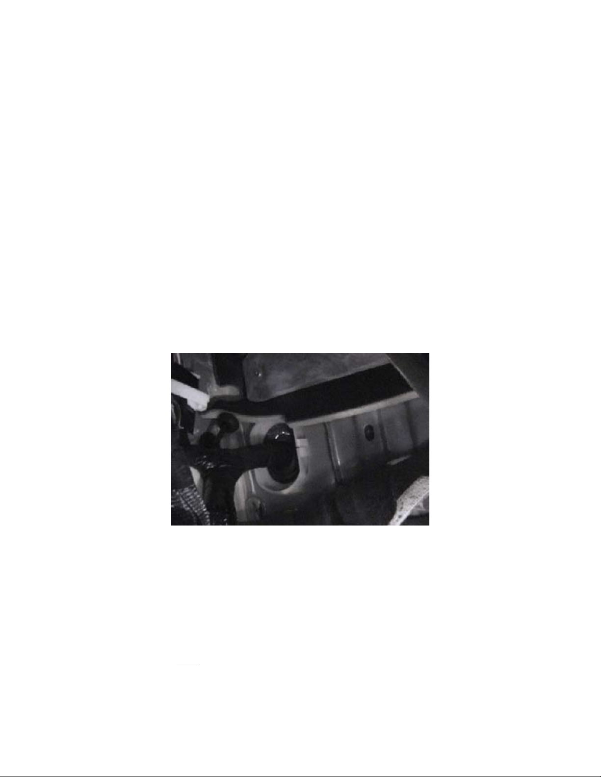
Locate the cold side of the brake light switch (BLS). This is the wire4.
that is normally cold, but has 12v+ when the brake pedal is depressed.
Crimp the spade onto the red wire on the LED and place the spade5.
into the flip-over connector.
Clip the flip-over connector onto the cold side of the brake light switch6.
wire.
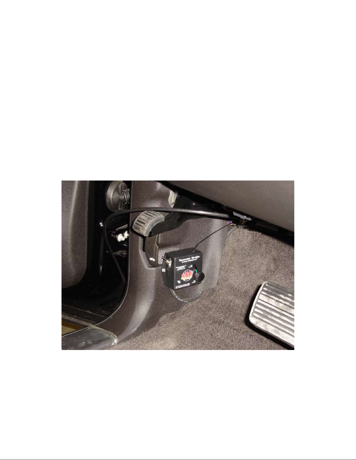
Using the provided 3 way crimp connector, connect the Black wire7.
from the LED to the Black wire on the G-Force Controller that was
mounted in Step 3.
* Careful attention must be given to disabling the light before driving the towed vehicle on public
streets. In this configuration, the toggle switch will disable/enable the light.

10
Step 5: Go Through the Firewall
Concerns:
Exercise extreme care if you make an additional hole in the firewall.•
Stay clear of any existing wiring, heat source, sharp edges, etc.•
Any openings made in the firewall must be plugged with an appropriate sealant to ensure•
that no fuel or exhaust fumes can enter the passenger area of the towed vehicle.
Locate an existing access of sufficient size through the firewall to accommodate the1.
G-Force Controller wire and the air hose. Almost all towed vehicles will have such an
access available, but, if not, you may need to drill a hole. In many cases, if an existing
grommet hole is not available, a small opening may be made in the car’s main wire
harness grommet. Be sure to stay clear of the car’s wiring.
2. Pass a straightened coat hanger or fish tape into the engine’s compartment from the
inside of the vehicle. In the passenger’s compartment, insert the coat hanger or fish
tape two to three inches into the air line and wrap it, along with the G-Force Controller
wiring, with electrical tape so that the assembly is as streamlined as possible. Apply
spray silicone or dish soap and gently pull it into the engine compartment through the
opening.
3. Pull out excess slack.
4. Route the airline to the Operating Unit and connect it to the air bulkhead.
A. Cut the air hose using an appropriate hose cutter. Make
sure the cut is straight. Air leaks can exist if the air hose is
not cut straightly.
B. Push the air hose in all the way. These fittings are tight, and the hose will snap
into place with two “clicks.”
Note: Should you find it necessary to remove an air hose, push the air hose in with one
hand, push on the outside ring of the pushlock connector with the other hand, and then
pull the air hose out. The ring will release the air hose.

11
Step 6: Mount the Cylinder
Special attention must be given to vehicles with adjustable pedals. Check for proper
clearance in all positions. When adjusting the cable, be sure that the pedals are
positioned closest to the driver’s seat. This will allow normal operation of the adjustable
pedals. Be sure to return the pedals closest to the driver’s seat when preparing to
tow, or the braking system will not function properly. As an option, the pedals may be
moved to the desired position and disabled. Do not depend on the fact that “no one
moves them.”
Find a location on the brake arm that will position the cylinder as low as possible but1.
as high as necessary not to interfere with normal driving. The higher the cylinder
is mounted, the less effective it is. Note: Some vehicles are equipped with a “hush
panel” under the dash which may need to be removed or modified. The cylinder
should be about 1-2” above the driver’s foot location while operating the vehicle.
Remember, during normal operation the brake pedal is depressed with the ball of
the foot.
Position the actuator. Place the actuator on the brake arm, slide the backplate2.
over the bolts, and position the actuator so that the brake arm is in the middle of
the bracket. Loosely thread the nuts on the bolts. The actuator should be mounted
so that when the brake pedal is depressed about two inches the actuator is
perpendicular to the firewall. This equates to about 1 inch above straight in line (See
Fig 14.1). Now tighten the nuts finger tight to temporarily hold the actuator in place.
Note: Be sure to cut away any sound deadening material before attempting to mount
the clamp.
Fig 14.1

12
Fig 14.2
3. Mark the anchor location on the firewall. Thread the cable through the anchor and
position the anchor on the firewall so that the cable has a direct line to the actuator
throughout the swing of the brake arm. Once the location is determined go ahead and
remove the slack in the cable leaving about 1/4” - 1/2” of slack. Hold the cable in place,
thread the cable around and through the anchor causing it to be “double looped” (Fig
14.2), and tighten the set screw to 15 inch-pounds. (About 1 full turn after contact).
The amount of slack has no effect on the amount of pressure or proportionality of the
systems. It only reduces the available stroke of the actuator. Excessive slack will result
in premature wear of the actuator cable. Important: The set screw has teeth designed
to grip the cable preventing slippage. Depending on the wrench used it is possible to
over-tighten and damage the cable. Keep in mind that with a 5” wrench only 3 lbs of
force is required, with a 7.5” wrench only 2 lbs., etc.
4. Using the provided self-drilling screw mount the anchor to the firewall. Visually verify
from the engine side of the firewall that the proposed location is acceptable for the self-
drilling screw. Often, a small pilot hole can be helpful in verifying the location. Mount the
clamp. If the firewall is found to be too thin to properly secure the anchor, a nut and bolt
may be needed to firmly secure the anchor.
5. Secure the Actuator. Verify that there is still only 1/4” - 1/2” of slack in the cable. It
may be necessary to move the actuator forward or backward if the amount of slack
changed during fitment. Tighten the bolts in a cross pattern until them backplate begins
to bend around the brake arm. This will “lock” the nuts and keep them from loosening
Figures 14.3 & 14.4 & Fig 14.5 on the following page.
6. Route a length of 1/4” DOT air line from the cylinder to the Stay-IN-Play Duo Unit
and connect it to the pushlock connector labeled “Air Out”.

13
Fig 14.4
Fig 14.5
Fig 14.3
*Cable breakage can only occur if there is an improper angle or if the cable is
overtightened in the anchor. Review this step carefully after the cylinder is mounted
to ensure proper installation. The actuator cable is a standard stainless steel aviation
cable with a tensile strength of 270lbs. The actuator is mechanically unable to break the
cable by force.

14
Step 7: Mount the Breakaway Switch
Mount the breakaway switch to the front of the towed vehicle as close to the center1.
of the towed vehicle as possible using the provided hardware. In many cases it can
be mounted to the front fascia in a manner that allows it to turn 90º when not in tow.
NOTE: Use 1/2” flex wrap to protect wiring from breakaway switch.
Step 8: Making the Electrical Connections
Note: Pull on each wire after the connector is applied to be certain it is secure.
Connect the red fuse holder to the battery or a hot terminal in the fuse block.1. DO NOT
PUT THE FUSE IN.
The brown wire from the Operating Unit and the orange/black wire from the breakaway2.
switch attach to the red fuse holder using the three-way crimp connector.
The blue wire from the Operating Unit attaches to the blue wire from the breakaway3.
switch.
The white wire from the G-Force Controller II attaches to the white wire of the4. tow
wiring AND to a suitable ground (preferably not the battery). Correct Grounding Is
Essential.
5. The red wire from the Operating Unit attaches to the red wire from the G-Force
Controller II.
6. The black wire from the Operating Unit attaches to the black wire from the G-Force
Controller II.
Note for #7 & 8
This installation assumes your tow wiring is based on a standard 4-wire connection from
the motor home. If you have a separate wire for the brake signal from the motor home
(amber turns on the towed and coach), find the wire that receives 12v (+) when the brake
pedal of the coach is depressed. That is the wire that the green and yellow wires are to be
attached to.

15
7. The green wire from the G-Force Controller attaches to the green wire of the tow wiring.
(See note page on 14).
8 The yellow wire from the G-Force Controller attaches to the yellow wire of the tow
wiring. (See note on page 14).
9. Insert the 20 amp fuse into the fuse holder.
Step 9: Connect the Cylinder Air Line
Connect the cylinder air line to the Operating Unit using the same method found in “Step
5-4.”
Step 10: Making the Vacuum Connection
First, locate the vacuum line coming from the brake booster and determine its size.
Then, select from one of the following options.
Note: This portion of the installation is for vehicles with vacuum-assisted brakes
ONLY. If you have hydra-boost brakes or are uncertain of your vehicle’s braking
configuration, call the Demco Help Line 800.543.3626 for assistance.
Some newer Ford products incorporate two vacuum lines from the booster
and require an addition check valve. Contact the Demco Help Line for details.
SPECIAL CONCERNS
Special care must be given to installing the engine check valve in the proper1.
orientation. (Motor, Unit Check Valve [black/green], Tee, Booster). Fig 12.2
Exercise care in routing the hose so that no kinks, sharp edges, heat, etc., will effect2.
the operation of the system.
Lubricate the check valve and tee with a small drop of dish soap or silicone spray.3.
This will help them slide easily into the vacuum hose.
Fig 12.1 Fig 12.2

16
11/32-3/8 I.D. HOSE SIZE (does not require hose clamps)
Locate the existing vacuum hose and determine where the check valve and the tee1.
will be inserted into the hose.
Cut the existing hose where the check valve will be inserted and install the check2.
valve. Take care not to cut too close to a bend in the hose that will not allow the
check valve to be inserted fully into the hose. (Black end toward the motor).
Cut the hose where the tee will be inserted and install the tee. Take care not to cut3.
too close to a bend in the hose that will not allow the tee to be inserted fully into the
hose.
Route the hose coming from the operating unit to the location where the tee will be4.
installed. (Stay away from sharp edges, heat sources and kinks).
Cut the hose coming from the Demco unit to the proper length and slide onto the5.
tee. Make sure enough excess is left to avoid kinks.
HARD PLASTIC VACUUM LINES
Cut a two inch length of hose from the provided 3/8” vacuum hose and slide one end1.
onto the green end of the check valve. Insert the tee into the other end.
Cut another two inch length of hose and insert the open end of the tee into it. (The2.
open end of the hose will slip over the smaller hard plastic tubing). Cut another two
inch length of hose and insert the open (black end) of the check valve.
Cut out a portion of the existing hard plastic tubing and slip the open ends of the3.
hose and hose clamps over the plastic tubing. Make sure the black end of the check
valve is toward the motor.
Put the enclosed clamps on the hose that the hard plastic tubing is inserted into (do4.
not overtighten).
Cut the hose coming from the Demco unit to the proper length and slide onto the5.
tee. Make sure enough excess is left to avoid kinks.
Fig 13.1

17
1/2-5/8 I.D. VACUUM LINES
Cut a two inch length of hose from the provided 3/8” vacuum hose and slide one end1.
onto the green end of the check valve. Insert the tee into the other end.
Cut another two inch length of hose and insert the open (black) end of the check2.
valve. Slide the hose adapter into the other end.
Cut another two inch length of hose and insert the open end of the tee into it. Slide3.
the other hose adapter into the other end.
Cut out a portion of the existing larger vacuum hose out and slip adaptors and hose4.
clamps into the open ends of the hose. Make sure the black end of the check valve
is toward the motor.
Cut the hose coming from the Demco unit to the proper length and slide onto the5.
tee. Make sure enough excess is left to avoid kinks.
Fig 13.2
Step 11: Testing the Install
Turn on the toggle switch.1.
Push the brake pedal down in the towed vehicle. The notification light will illuminate. If2.
not, check the brake-light switch connection and the ground connection.
Remove the breakaway pin and observe the operation of the cylinder. Note the cable3.
attached to the firewall. It should be as close to an inch above being straight with the
cylinder as possible (see FIG 14.1 page 11). When it is in this location, the cable will be
straight with the cylinder when the brake pedal is in the down position. The vacuum pump
will run continuously, and apply the brakes of the towed vehicle. As the pump runs, more
brake effort is applied to the towed vehicle until the maximum effort is reached. Let the
pump run for about 10 seconds and replace the breakaway pin.

18
4. Verify that the brakes in the towed vehicle are fully released. Inspect the cable clamp
and verify the cable has not slipped in the clamp.
5. Tape all electrical connections with a high quality electrical tape, and use cable ties to
secure the wires.
6. With the G-Force Controller knob at the bottom of the slot, go to the coach and press
on the brake pedal. The tow wiring must be connected. Do not connect the tow bar.
Confirm the activation of the system by checking the light in the back up monitor. If the
system fails to activate, refer to Step #12-1 and re-test.
Step 12: Adjusting the G-Force Controller
Note: The Stay-IN-Play Duo’s activation is progressive in nature. It is designed to activate
briefly in normal stopping (20+ MPH) and longer in harder/panic stopping. When
adjusted correctly, the Stay-In-Play Stay-IN-Play Duo WILL NOT activate while
stationary.
Locate the vehicles on level ground and turn the switch to “ON.” Place the black knob on1.
the G-Force Controller at the bottom of the slot and have an assistant step on the brake
pedal of the coach. At this point the system should activate. If it does not, remove the
front screw from the G-force Controller and lower it until the unit activates and then re-
secure it in this location. Slowly raise the knob up. The system may begin chattering,
keep raising the knob. As soon as the pump shuts off completely and then go up another
1/8”. Tighten down the black knob to ensure it does not move.
Test drive the coach while pulling the towed. Drive and stop2. NORMALLY as these are
the conditions for which you want to configure the braking system. The system should
not come on in normal stopping below 20 mph.
If while traveling the system activates too often, raise the knob 1/16”. Repeat step 2.3.
If while traveling the system doesn’t activate often enough, lower the knob 1/16”. Repeat4.
step 2.
*The Stay-IN-Play Duo system operates the brakes of the vehicle in the same manner as
you would. The more often it comes on, the more quickly the brakes of the vehicle will
wear. The above adjustment will equal normal driving mileage on the brakes.
Step 13: The Breakaway Cable
Clip the breakaway cable to the hitch-receiver tow-cable holes on the coach and clip the lanyard to the
loop on the breakaway plug. The length of the cable should be long enough that it will not pull out on
the tightest possible turns made in either direction. Also route the cable so that it will not get caught
on the tow bar. It should be short enough that it will pull out before the towed reaches the end of the

19
At Demco we exercise great care in building and packaging your unit. All operating units are
thoroughly bench tested before being shipped. We encourage you to contact our Help Line
any time you have questions about the installation or operation of your Demco Vacuum-
Assisted Brake.
VACUUM/AIR
Vacuum Pump will not shut off:
Check to see that the breakaway pin is secure.1.
If the pump continues to run call the Help Line 800.543.3626.2.
Actuator not moving brake pedal:
Check cable tension (Step 6).1.
Remove actuator air line and check for pressure. If there is no/weak pressure check line2.
for a pinch, kink, or puncture.
If no issue is found call the Help Line 800.543.3626.3.
WIRING
Check the fuse and the holder at the battery and the WHITE wire connection. Also, be sure
that the 20-amp fuse is installed in the fuse holder.
Unit failed to operate when the RV brakes were applied:
Be sure the toggle switch is in the on position. Using a voltmeter or a test light, determine1.
if there is 12v (+) between the brown wire and the black ground wire at the Operating
Unit. There should be 12v (+) between these two wires at all times, when the switch is
on.
Check the orientation of the G-Force Controller. It may need to be tipped slightly2.
forward.
Check continuity from the white wire to the frame. If there isn’t continuity, reground the3.
white wire to the frame of the towed vehicle.
Troubleshooting
Stay-In-Play Stay-IN-Play Duo Installation

20
4. With the RV brakes applied check for 12v (+) between the Demco GREEN wire and the
Demco BLACK wire. If no or low voltage is present, check the scotch lock connection to the
towed vehicle’s tow wiring. Remember the 12v (+) for this is coming from the coach. Check
to see that the coach is grounded properly to the car in the tow wiring.
5. Apply the RV’s brakes with the tow wiring connected. Lower the knob on the G-Force
Controller. If you check the voltage and the unit still does not operate, call the Help Line
800.543.3626.
Breakaway failed to operate the brakes:
Make sure the toggle switch is turned on.1.
Remove the breakaway plug from the front of the towed vehicle. Test for 12v (+) between2.
the blue wire and the black wire on the Operating Unit. There should be a 12v (+) at that
time, and ONLY then. If not, check continuity to ground with the black wire. Check the
connection at the battery and the fuse. Check the connection of the blue wire.
Turn off toggle switch. Clean breakaway switch by spraying contact cleaner or spray3.
silicone into switch and pull the pin in and out 3-5 times. It may be necessary to use a
fingernail file between the points if the switch is especially corroded. Inspect the o-ring
on the lanyard-side of the pin to prevent future corrosion.
Unit pulsates with turn signals:
1. Unit sensitivity is too low. Refer to Step 12 to set the sensitivity.
2. Be sure that the G-Force Controller is level and properly oriented. (Step 3)
What now?
If the problem has not been solved, you will need technical assistance from Demco
Manufacturing, Inc. Call us at 1-800-543-3626.
After installation, the brake does not apply while stationary.
1. The Stay-IN-Play Duo’s activation is progressive in nature. It is designed to activate
briefly in normal stopping (20+ MPH) and longer in harder/panic stopping. When adjusted
correctly, the Stay-In-Play Stay-IN-Play Duo WILL NOT activate while stationary.
Table of contents
Other Demco Automobile Accessories manuals

Demco
Demco Hijacker 5998 Ultra Slide User manual

Demco
Demco Tow-It 2 User manual

Demco
Demco Aluminator User manual

Demco
Demco Excali-Bar 9511004 User manual

Demco
Demco Hijacker 6040 User manual

Demco
Demco KAR KADDY 3 User manual

Demco
Demco BASE PLATE User manual

Demco
Demco Hijacker 6005 UMS User manual

Demco
Demco 6040 User manual

Demco
Demco GT300 User manual