Denios Bio.x C500 User manual
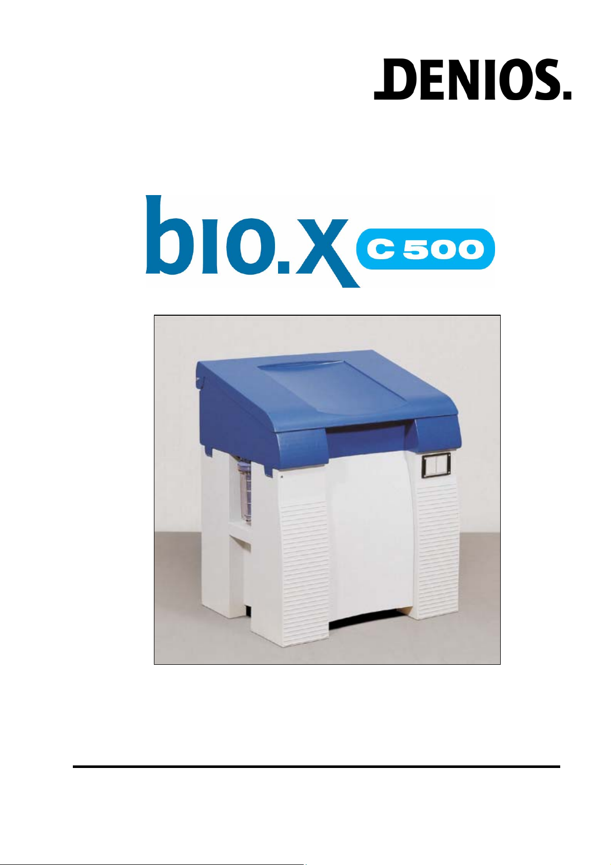
Cleaning Table
USERS MANUAL 07/2008
138514_EN_BA_105

bio.x C500 135147 Page 2 of 12 07/2008
Inhaltsverzeichnis
1. General Instructions.......................................................................................................... 2
2. Safety instructions ............................................................................................................ 3
3. Technical data.................................................................................................................... 3
4. Product description........................................................................................................... 4
4.1 Intended use .................................................................................................................. 4
4.2 Layout and how it works................................................................................................. 4
5. Initial Operation ................................................................................................................. 5
5.1 Electrical connection ...................................................................................................... 5
5.2 Filling with the cleaning fluid .......................................................................................... 5
6. Control panel ..................................................................................................................... 5
6.1 Function indicators on the display. ................................................................................. 6
7. Operation............................................................................................................................ 6
8. Maintenance....................................................................................................................... 7
8.1 Fill level .......................................................................................................................... 7
8.2 Additive .......................................................................................................................... 7
8.3 Filter ............................................................................................................................... 7
8.4 Cleaning fluid ................................................................................................................. 7
8.5 Refill items ..................................................................................................................... 8
8.6 Replacement parts (see also product description page 5) ............................................. 8
9. Optional Accessories........................................................................................................ 9
10. Notes regarding disposal.............................................................................................. 10
11. Faults.............................................................................................................................. 10
12. Connection Diagram...................................................................................................... 11
13. EC Declaration of Conformity....................................................................................... 12
1. General Instructions
This user manual is for the bio.x parts cleaning unit C500. It contains all the information needed regarding
correct startup, trouble-free operation, maintenance, removal from service and disposal. The information
and instructions in this user manual have to be observed and adhered to.
If the instructions are strictly followed in accordance with the user manual, we accept liability within the
scope of our conditions for guarantees.
Without approval from the manufacturer no changes, extensions or modifications may be made to the
product. For changes made without approval from the manufacturer no liability is assumed and the
guarantee expires.
National regulations and safety regulations have to be adhered to.

bio.x C500 135147 Page 3 of 12 07/2008
2. Safety instructions
This unit can only be used safely if you read this user manual carefully and strictly follow the instruc-
tions it contains. This user manual is an integral part of this unit and must be available to the person-
nel who operate the unit at all times.
Such staff must be familiarised with the user manual with particular attention being paid to prohibitions
and hazard warnings.
The mains supply connection has to be in accordance with the corresponding regulations (VDE 01000 -
Association of German Electricians). For safety reasons the equipment must be only operated, if a Resid-
ual Current protective Device (RCD) with a release current of 30 mA is connected upstream.
This must be checked by a qualified electrician.
In accordance with the German BGV A3 electrical equipment has to be examined in regular inter-
vals.
The equipment must be set up on a suitable stable, level surface.
Detergents which contain highly flammable substances must not be used. Use only detergents ap-
proved by DENIOS for this unit.
3. Technical data
Dimensions 1010 x 785 x 1140 mm
Net weight 55 kg
Power consumption 1.1 kW
Electrical connection 1/N/PE 230V∼
Pre-fusing 10 A
Work surface height 950 mm
Load capacity 250 kg
Tank LDPE
Maximum fill capacity 100 l
Minimum fill capacity 60 l
Usable work surface 930 x 545 mm
Heater Stainless steel (1.4541) heating element output 1 kW
Level switch Minimum fill level (approx. 60 l)
Operating temperature Set at 41°C in the factory
Pump, flow rate approx. 200 l/h
bio.x C500 135147 Page 4 of 12 07/2008
4. Product description
4.1 Intended use
The bio.x parts cleaning unit is used to clean oil and grease from work pieces in an efficient, environmentally
sustainable way using exclusively cleaning fluids authorised by DENIOS.
Other detergents such as degreasers or alkali cleaning agents must not be used!
Solvents, disinfectants, alkali or acidic fluids, carburettor and diesel fuels or turpentine must not be
poured into the appliance.
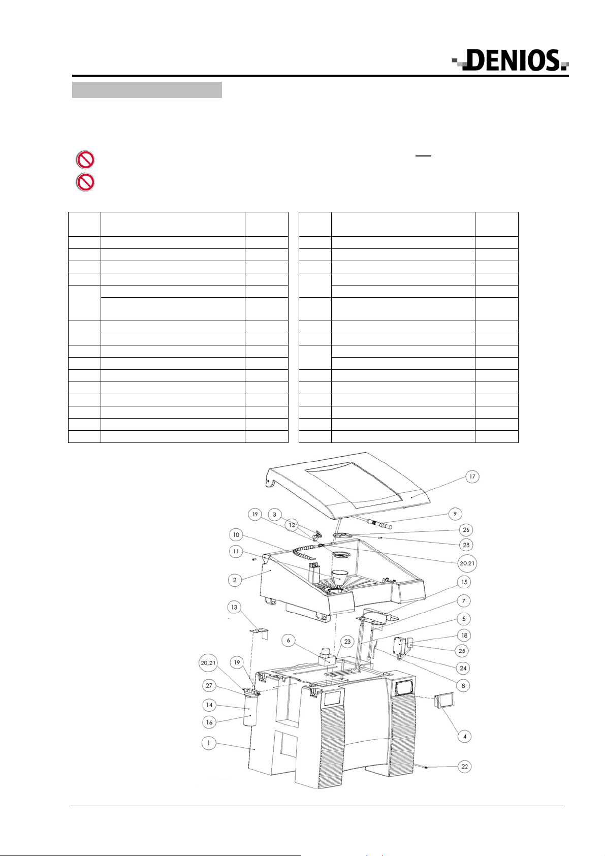
4.2 Layout and how it works
Item Description Mat.
No. Item Description Mat. No.
1 Base with tank - 15 Mounting plate 151683
2 Stand top - 16 Filter insert 135348
3 Ball valve 135279 17 Lid set (optional) 135148
4 Control unit 169678 Aerator 230 V 135310
Heating system 230 V 177340 18 Aerator 115 V 138350
5 Heating system 115 V 177342 19 Screw-on connecting piece
G3/8“
135301
Pump 230 V 134979 20 Connector assembly AD 3/8“ 135304
6 Pump 115 V 134976 21 Tubular pin insert AD 3/8“ 135306
7 Level switch 135274 Power cable 230 V 160517
8 PT 100 temperature sensor 135266 22 Power cable 115 V 142016
9 Brush 135277 23 Screw-on pump 135302
10 Flexible hose with flat nozzle 135289 24 Air hose 175289
11 600 µm filter screen 135256 25 Aerator 138281
12 Coarse filter 135255 26 Brush hose 151100
13 Filter bracket 160677 27 O-ring for filter 150609
14 Filter set (optional) 135149 28 Plug 153098
bio.x C500 135147 Page 5 of 12 07/2008
5. Initial Operation
After removing the packaging, check the unit casing and operating components for any possible damage
caused in transit. If such damage is found, do not connect the unit to the mains. Report damage immediately
to the carrier who delivered the unit and to DENIOS AG at the service number indicated above. The original
packaging should be kept.
Place the unit in a dry, stable location as required.
The floor must be level. If necessary, level out any uneven surfaces with suitable shimming material.
5.1 Electrical connection
The unit is connected to the customer's mains supply via the power cable and plug.
Mains voltage: The voltage of the power source has to comply with the details on the identification place of
the appliance
Warning: The mains supply must be fitted with a residual current protective device in accordance with
DIN VDE (Association of German Electricians) 0100! (See section 2)
5.2 Filling with the cleaning fluid
Two different cleaning fluids can be used in the Part Cleaning Unit C500.
a) Bio-Power cleaning fluid
•Pour 100 l (5 canisters) of Bio-Power cleaning fluid into the tank.
•Connect the unit to the mains. "On" will be shown on the display for 3 seconds. The heating system
switches on automatically. The warming-up process can take up to 2.5 hours, depending on the initial
temperature. The operating temperature is set at 41º C in the factory and cannot be changed. When the
operating temperature is reached, "41" will appear on the display.
The aerator will work continuously after the unit is switched on.
•Once the operating temperature is reached add the additive with the micro-organisms (1 can x 100 g) to
the fluid. The micro-organisms take 24 hours to become active. It is therefore recommended to set up the
unit for operation just before the weekend, for instance.
The parts cleaning unit is then ready for operation.
b) bio.x detergent (ready-for-use solution incl. micro-organisms)
•Pour 100 l (5 canisters) of Bio-Power cleaning fluid into the tank.
•Connect the unit to the mains. "On" will be shown on the display for 3 seconds. The heating system
switches on automatically. The warming-up process can take up to 2.5 hours, depending on the initial
temperature. The operating temperature is set at 41º C in the factory and cannot be changed. When the
operating temperature is reached, "41" will appear on the display.
The parts cleaning unit is then ready for operation.
The aerator will work continuously after the unit is switched on.
The two detergents should not be mixed together as far as this is possible.
Other detergents such as degreasers or alkali cleaning agents must not be used.
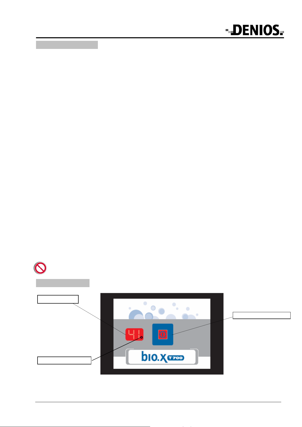
6. Control panel
Multi-control button
Display
LED heater
bio.x C500 135147 Page 6 of 12 07/2008
6.1 Function indicators on the display.
Function Indicator
Warming-up process Display ’41’ flashing, LED heater on
Rising horizontal bars
Operating temperature reached,
heater off
Display ’41’ flashing, LED heater off
Operating temperature reached,
heater on
Display ’41’ flashing, LED heater on
Excess temperature Temperature indicator flashing
when T>41°C
Energy-saving mode Display ‘30’
Fault messages,
see section 6.2 (fault messages)
Display ‘LO’; F1 to F7
7. Operation
Place the parts to be cleaned in the cleaning basin in the bio.x Parts Cleaning Unit.
Do not exceed the maximum load of 250 kg!
Switch on the water pump by pressing the multi-control button on the controls.
Depending on the 3-way ball valve switch setting, parts can be cleaned by:
- rinsing them using the flexible hose and nozzle
- using the brush with detergent running through
Note: When on the middle setting, both outlets are opened.
The dirty detergent runs back into the tank via the middle plug outlet where special micro-organisms remove
oil and grease contaminants.
The water pump automatically switches off after about 60 minutes. The water pump can also be switched on
and off by pressing the multi-control button on the control panel.
Note:
When interrupting work, switch off the water pump only and do not disconnect the unit from the mains, so the
detergent remains warm. The micro-organisms in the detergent require heat and oxygen to degrade the oil
and grease. For this reason, the heating system maintains the temperature of the detergent at 41º C and an
aerator ensures oxygen is permanently fed to the micro-organisms. If the unit is switched off, or it breaks down
for a long period of time, the micro-organisms become inactive.
Energy-saving mode
The unit can be switched to energy-saving mode during downtimes such as night-time, weekends, or com-
pany holidays. To do so, the multi-function button is pressed for 3 seconds. "30" will be shown on the dis-
play. The temperature is maintained at 30º C in energy-saving mode. The micro-organisms remain active at
this temperature and optimum oil and grease degradation is guaranteed.
You can switch from energy-saving mode by just pressing the button again and the unit will heat the deter-
gent to 41º C again. The warm-up stage takes about an hour, depending on the ambient temperature. Once
this temperature is reached and "41" is shown continuously on the display, the unit is ready for operation with
optimum cleaning assured.
bio.x C500 135147 Page 7 of 12 07/2008
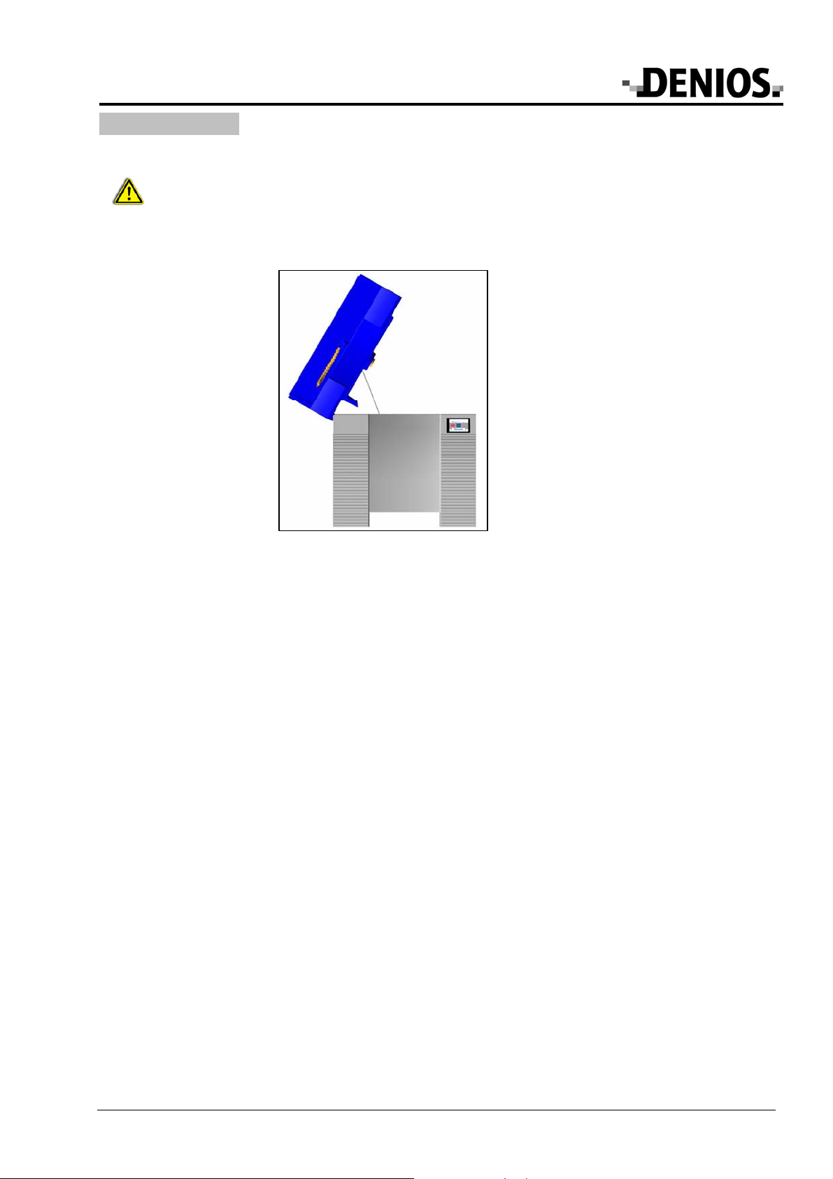
8. Maintenance
Warning! Before starting work on the cleaning table fixtures, switch off the electrics and unplug
from the mains! Test the equipment to ensure the power is off!
The unit can be opened at the side for servicing or to fill the tank with fresh detergent. To do so, lift up the
right-hand side of the unit top and prop it up using the bar you can find inside.
Servicing position for unit top
8.1 Fill level
Check the fill level against the markings on the tank wall regularly so you can refill to make up for any losses
through evaporation and removal. If the fill level falls under a minimum of 60 litres (lowest marker line), the
pump and the heating system switch off automatically for safety reasons. In such a case, "LO" is shown on the
display. Re-fill the detergent until the top marker line is reached. The message will disappear once there is
enough detergent in the tank.
8.2 Additive
More additive should be put in every 6 months to replenish the micro-organisms.
After refilling, the detergent must be left to stand for 24 hours so that the micro-organisms can become active.
It is therefore recommended to refill with the additive before a weekend.
8.3 Filter
The washstand is equipped with two filters as standard. A stainless steel perforated filter on the washstand
surface and a synthetic filter for impurities underneath. It is recommended to clean these filters on a daily
basis. To do so, remove the filters from the unit and rinse with water.
8.4 Cleaning fluid
The cleaning fluid has to be replaced if
- there is a significant fall in the cleaning performance
- when checking the fill level there are notable sediment deposits on the floor of the tank
After you have taken out the used cleaning fluid, the tank has to be freed of any sediment residue.
Please follow the same process when inserting the new fluid as for the initial operation.

bio.x C500 135147 Page 8 of 12 07/2008
8.5 Refill items
Accessories Description Item number
Bio-Power cleaning fluid 20-litre canister 175715
Bio-Power cleaning fluid 200-litre drum 169787
Additive for oil and grease degradation 100g can for 100 l detergent 168625
Set (cleaner and additive) for initial filling
and refills
5 x 20-litre canisters of Bio-Power cleaning fluid
100 g can of additives 169789
Cleaning fluid bio.x 20-litre canister 130032
Set for initial filling and refills 5 x 20-litre canisters 130030
8.6 Replacement parts (see also product description page 5)
Description Item number
Hose between filter and tap 167923
Hose between pump and filter 167924
Hose bracket 141247
Hose for aerator 175289
Filter insert for fine filter (optional)
Central support bracket and nylon filter
150043

bio.x C500 135147 Page 9 of 12 07/2008
9. Optional Accessories
Accessories Description Item number
Residual current device
adapter
Adapter for fuse protection for the appliance
Release current: 30 mA,
Protection category: IP44
177335
Protective gloves
(1 pair)
with extra long gauntlet, internally padded with cotton fabric
Length: 640mm
Size: 10
EN388: 4121
Resistance: good protection against detergents, alkali, oils and
greases
163613
Filter The additional fine filter can be installed between the pump and runback. 161718
Filter screen type 454
Fineness 80 μm
Can be used as an alternative for filter screen (12) 161047
Perforated metal insert To protect the work surface of the cleaning table
Makes it possible to work without tilting
152605
Dolly For portable use of the parts cleaning unit 154288
Curved wash brush For cleaning curved edges, prevents signs of fatigue when working for a
long time.
172560
Stainless steel brush To remove heavily crusted dirt from insensitive parts 173926
Wet vacuum cleaner
Type SV 6.16 To completely empty the tank, also suitable for sludge 123224
Fine filter (14)
The optional fine filter, which can be fitted on the left-hand side of the unit, should be checked weekly and
cleaned if necessary. Release the filter cover by turning it anti-clockwise. Remove the filter cartridge and rinse
it thoroughly under running water, or replace it with a new cartridge. Reinsert the cartridge and screw the cas-
ing firmly back into place. Ensure the seal is in the correct position.
A fine filter retrofit should be carried out in accordance with fitting instructions 135149_DE_DE_BA_100.
Draining device
Used detergent can be let straight out via the ball stopcock underneath the tank.
A draining device retrofit should be carried out in accordance with fitting instructions 135151_DE_DE_BA_100.
Lid (17)
Closing the lid reduces loss of detergent due to evaporation, saves on heating costs and prevents the basin
from getting dirty unnecessarily.
Two M8 screw threads are provided on the unit to retrofit a lid. Attach the lid using the socket cap
screws supplied in the accessory kit. Warning: Do not tighten the screws too much as the user must
be able to open the lid easily.

bio.x C500 135147 Page 10 of 12 07/2008
10. Notes regarding disposal
Detergent
The relevant waste code number for a contaminated substance depends on the type of dirt removed and not
on the type of detergent. The applicable waste code number can be found in the European Waste Catalogue.
Contaminated substances can often be disposed of as a water and oil mixture in other hydrous systems.
Unused fluids can be fed into waste water treatment plant while taking into account local regulations regarding
wastewater disposal.
Appliance
According to the electronic and electrical appliance regulations, owners of disused appliances
are legally required to dispose of such items separately. Please help to protect the
environment by not disposing of disused appliances with household waste.
11. Faults
Warning! Before starting work on the cleaning table fixtures, switch off the electrics and unplug from the
mains Test the equipment to ensure the power is off
Display
screen Fault Cause Solution
Detergent cold, heating system not
working
Heating system plug con-
tacts are loose
Check plug contacts to en-
sure connected properly.
F 1 Detergent cold, heating system not
working
1. The pump is not connected
or is faulty;
2. Fuse faulty
3. Temperature limiter has
been triggered
1. Connect heating system;
replace if necessary
2. Replace fuse.
3. Have unit checked, tem-
perature limiter must be ac-
tivated
F 2 Wash pump not working
1. The pump is not connected
or is faulty;
2. Fuse faulty
1. Connect wash pump; re-
place if necessary
2. Replace fuse.
F 3 Aerator not working
1. Aerator is not connected, or
is faulty;
2. Fuse faulty
1. Connect aerator; replace if
necessary
2. Replace fuse.
F 4 Level switch not working Level switch not connected Connect level switch
F 5 Short-circuit in level switch Level switch faulty Replace level switch
F 6 Detergent cold, temperature sen-
sor not working
Temperature sensor not
connected
Connect temperature sen-
sor
F 7 Short circuit in temperature sensor Temperature sensor faulty Replace temperature sen-
sor
LO Heating system and wash pump
not working
1. Fill level fallen below mini-
mum level
2. Float switch dirty and in the
wrong position
1. Refill with detergent
2. Clean the float-switch
mechanism
Overheating
If the maximum permitted temperature (41°C) is exceeded, the current temperature will be shown as a flashing
warning message on the display. If such a case arises, switch off the parts cleaner immediately. Then check
the temperature sensor PT 100 is in the correct position (3).
The equipment is fitted with a temperature limiter to prevent damage from overheating. This switches the heat-
ing system off if the maximum temperature is exceeded.
If overheating is not caused by the temperature sensor being in the wrong position, a service technician must
be called in to find the cause and make necessary repairs.

bio.x C500 135147 Page 11 of 12 07/2008
12. Connection Diagram
Thermal circuit breaker
Heater
Pump
A
ir pump
Level
Foot switch
brown
black
blue
bio.x C500 135147 Page 12 of 12 07/2008
13. EC Declaration of Conformity
EC Declaration of Conformity
For the purpose of the EC Machinery Directive 98/37/EC, Annex II A
Herewith we, the DENIOS AG, Dehmer Straße 58-66, 32549 Bad Oeynhausen, declare that the design
of our product:
Cleaning Table bio.x
complies with the following relevant provisions:
;EC Machinery Directive 98/37/EC
;EC Low Voltage Directive 73/23/EC
;EC Electromagnetic Compatibility Directive 93/68/EC
Applied harmonised standards:
;EN 349
;EN 60 204-1
;EN 12100, -1, -2
to which our declaration refers.
This declaration becomes invalid in the case of incorrect use and product modifications which were
not agreed with the manufacturer.
Bad Oeynhausen 11.09.2007 ..............................................
Theodor Breucker
- - Board of Directors -
DENIOS AG
Dehmer Straße 58-66
32549 Bad Oeynhausen
Tel.: +49 (0)5731 7 53 – 0
Fax: +49 (0)5731 7 53 – 197
You`ll find your local partner on our InterNet side www.denios.com
Table of contents
Other Denios Cleaning Equipment manuals


Popular Cleaning Equipment manuals by other brands

e.ziclean
e.ziclean hobot 388 manual

Clean Logix
Clean Logix ALX-PRO user manual

Clean Logix
Clean Logix BLX-700-GEN2 user manual

Auto Care Products
Auto Care Products Clean Park quick start guide

Streamline
Streamline STREAMLFO SF-TR25L-000 instruction manual

Parkside
Parkside 102800 original operation manual

Roller's
Roller's Metro 22 operating instructions

Elcometer
Elcometer Sagola Classic P1 instruction manual

Bissell
Bissell CrossWave Cordless 2551 Series Battery removal instructions

Electric Eel
Electric Eel S Operator's manual

Magnum
Magnum XP user manual

Bluerock Tools
Bluerock Tools SDS200 Operational manual


