Denon DVP-602CI User manual

DENON
VIDEO PROCESSOR
DVP-602CI
Owner's Manual
IG!JlI
Graphical User Interface
Use
this
manual
in
combination
with
the
operating guide displayed on
the
GUI screen.
GUI
Menu
Operation
(Eif'page
15)
GUI
Menu
Map
([§'page
16)
Language (GT'page 21)

oSAFETY PRECAUTIONS SAFETY INSTRUCTIONS
13
Power-Cord Protection -Power-supply cords should be routed so that they
are not likely to be walked
on
or pinched by items placed upon or against
them, paying particular attention
to
cords at plugs, convenience receptacles,
and the pOint where they eXit from the product.
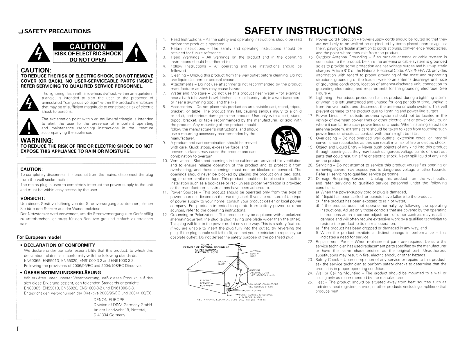
15 Outdoor Antenna Grounding -
If
an
outSide antenna or cable system
IS
connected to the product, be sure the antenna
or
cable system
IS
grounded
so
as
to provide some protection against voltage surges and built-up static
charges. Article
81
0of the National Electllcal Code, ANSI/NFPA
70,
prOVides
Information With regard to proper grounding of the mast and supporting
structure, grounding of the lead-In wire to
an
antenna discharge unit, size
of grounding conductors. location of antenna-discharge unit, connection to
grounding electrodes, and requirements for the grounding electrode. See
Figure A.
16
lightning
-
For
added protection for thiS product during alightning storm,
or
when
it
IS
left unattended and unused for long periods of time, unplug it
from the wall outlet and disconnect the antenna
or
cable system.
ThiS
will
prevent damage to the product due to lightning and power-line surges
17.
Power Lines -An outSide antenna system should not be located
in
the
viCinity
of
overhead
power
lines or other electllc light or power
CirCUitS,
or
where it can fall into such power lines or CIrcuits. When Installing
an
outside
antenna system, extreme care should be taken to keep from touching such
power lines or cirCUits
as
contact
with
them might
be
fatal.
18. Overloading -
Do
not overload wall outlets, extension cords, or integral
convenience receptacles
as
this
can
result
In
aIIsk
of
fire or electllc shock.
19
Oblect and
LiqUid
Entry -Never push objects of any kind into
thiS
product
through openings
as
they may touch dangerous voltage points or short-out
parts that could result
in
afire or electllc shock. Never spill liquid of any kind
on
the product.
20. Servicing -
Do
not
attempt
to
service this product yourself
as
opening
or
removing covers may expose you to dangerous voltage
or
other hazards
Refer
all
servicing to qualified service personnel
21
Damage Requiring SerVice -Unplug this product from the wall outlet
and refer serVicing to qualified service personnel under the follOWing
conditions:
al
When the power-supply cord or plug
is
damaged,
b)
If liquid
has
been spilled, or objects have fallen into the product.
cl If the product has been exposed to
rain
or water,
dl If the product does not operate normally by following the operating
instructions. Adjust only those controls that
are
covered
by
the operatin9
instructions
as
an
improper adjustment
of
other controls may result
in
damage and Will often require extensive work by aqualified technician to
restore the product to its normal operation,
el If the product
has
been dropped or damaged
In
any way. and
fl When the product exhibits adistinct change
in
performance -this
,nd,cates aneed for service
22
Replacement Parts -When replacement parts are required,
be
sure the
service technician
has
used replacement parts specified
by
the manufacturer
or have the same charactellstlcs as the original part. UnauthollZed
substitutions may result
In
fire, electllc shock, or other hazards
23
Safety Check -Upon completion of any service
or
repairs to this product,
ask
the service technician to perform safety checks to determine that
the
product
IS
in
proper operating condition.
24 Wall
or
Ceiling Mounting -The product should
be
mounted to awall or
ceiling only
as
recommended by the manufacturer
25. Heat -The product should be situated away from heat sources such as
radiators, heat registers, stoves, or other products (Including ampliflersl that
produce heat
ANTENNA
DISCHARGE UNIT
INEC
SECTION
810-20\
GROUNDING
CONDUCTORS
{NEC
SECTION
810-2\)
ELECTRIC
~~~~~~~NC:T--.I
cr-
I
2
4
FIGURE
A
EXAMPLE
OF
ANTENNA
GROUNDING
AS
PER
NATIONAL
ELECTRICAL CODE
_QQWER
SERVICE
GROUN[)I"<G
ELECTRODE
SYSTEM
NEC
-
NATIONAL
ELECTRICAL
CODE
,NEC
ART
250
PART
HI
3
5
6
8.
Read
Instructions -All the safety and operating Instructions should be read
before the product
IS
operated.
Retain Instructions -The safety and operating instructions should be
retained for future reference
Heed Warnings -All warnings
on
the product and
,n
the operating
Instructions should be adhered to.
Follow Instructions -All operating and use instructions should be
followed.
Cleaning -Unplug
thiS
product from the wall outlet before cleaning.
Do
not
use liquid cleaners or aerosol cleaners.
Attachments -Do not use attachments not recommended
by
the product
manufacturer
as
they may cause hazards
Water and Moisture -Do not use this product near water -for example,
near abath tub, wash bowl, kitchen
Sink,
or
laundry tub,
,n
a
wet
basement;
or near asWimming pool; and the like.
Accessones -Do not place thiS product
on
an
unstable cart, stand. tripod,
bracket, or table. The product may fall, causing serious inlury to achild
or adult. and senous damage to the product. Use only
with
acart, stand,
tnpod, bracket, or table recommended by the manufaclUrer, or sold With
the product. Any mounting of the product should
follow the manufacturer's instructions, and should
use amounting accessory recommended by the
manufacturer
Aproduct and cart combination should be moved
with
care. Ouick stops, excessive force, and
uneven surfaces may cause the product and cart
combination to overturn
10 Ventilation -Slots and openings
in
the cabinet
are
provided for ventilation
and to ensure reliable operation of the product and to protect It from
overheating, and these openings
must
not be blocked or covered. The
openings should never be blocked by placing the product on abed, sofa,
rug, or other similar surface.
ThiS
product should not be placed
in
abuilt-in
Installation such
as
abookcase or
rack
unless proper ventilation
IS
proVided
or
the manufaclUrer's inStructions have been adhered to.
Power Sources -
ThiS
product should
be
operated only from the type of
power source indicated
on
the marking label.
If
you
are
not sure
of
the type
of power supply to your home, consult your product dealer or local
power
company
For
products Intended to operate from battery power, or other
sources, refer to the operating instructions.
12.
Grounding or Polanzation -This product may be equipped With apolarized
alternating-current line plug
(a
plug having one blade wider than the other)
ThiS
plug will fit into the
power
outlet only one way. This
IS
asafety feature.
If you are unable to insert the plug fully Into the outlet, try reversing the
plug.
If
the plug should still fail to fit. contact your electncian to replace your
obsolete outlet Do not defeat the safety purpose of the polarized plug.
11
9
•DECLARATION OF CONFORMITY
We
declare under our sole responsibility that this product, to which this
declaration relates,
is
in
conformity with the following standards:
EN60065, EN55013, EN55020,
EN61
000-3-2 and EN61000-3-3
FollOWing the
prOVISions
of
2006/95/EC and 2004/1 08/EC Directive
•UBEREINSTIMMUNGSERKLARUNG
WIr
erklaren unter unserer Verantwortung,
dar.,
dleses Produkt. auf
das
sich diese Erklarung bezieht, den folgenden Standards entsprrcht:
EN60065, EN55013, EN55020,
EN61
000-3-2 und
EN61
000-3-3
Entspllcht den Verordnungen der Dlrektlve 2006/95/EC und 2004/1 08/EC ,
DENON EUROPE
DiVision of
D&M
Germany GmbH
An der Landwehr
19,
Nenetal,
0-41334 Germany
CAUTION:
TO REDUCE THE RISK OF ELECTRIC SHOCK, DO
NOT
REMOVE
COVER (OR BACK).
NO
USER-SERVICEABLE PARTS INSIDE.
REFER
SERVICING TO QUALIFIED SERVICE PERSONNEL.
CAUTION:
To
completely disconnect this product from the mains, disconnect the plug
from the wall socket outlet.
The mains plug
IS
used to completely interrupt the power supply to the unit
and
must
be within easy access by the user.
VORSICHT:
Um d,eses Gerat vollstandlg von der Stromversorgung abzutrennen, zlehen
S,e
b,tte den Stecker aus der Wandsteckdose
Der Netzstecker wlrd verwendet. um die Stromversorgung zum Gerat vbllig
zu
unterbrechen; er muss fur den Benutzer gut und elnfach
zu
errelchen
seln
AThe lightning flash with arrowhead symbol, within
an
equilateral
Iii
triangle,
is
Intended to alert the user to the presence of
un
Insulated "dangerous voltage" within the product's enclosure
that may be
of
sufficient magnilUde to constitute arisk
of
electric
shock to persons.
1
II
'AThe exclamation
pOint
within
an
equilateral triangle
IS
Intended
to alert the user to the presence of Important operating
and maintenance (servicing) instructions
in
the literature
accompanying the appliance.
I
WARNING:
TO REDUCE THE RISK OF
FIRE
OR
ELECTRIC SHOCK, DO
NOT
EXPOSE THIS APPLIANCE TO RAIN
OR
MOISTURE.
For European model

•Do not let foreign objects into the unit.
•
Lassen
Sis
keine
fremden
Gegenstande
in
das
Gerat
kammen.
•
Do
not
let
insecticides,
benzene,
and
thinner
come
in
contact
with
the
unit.
•
Lassen
Sie
das
Gerat
nicht
mit
Insektiziden,
Benzin
oder
Verdunnungsmitteln
in
Beruhrung kommen.
•
Never
disassemble
or
modify
the
unit
in
any
way.
•
Versuchen
Sie
niemals
das
Gerat
auseinander
zu
nehmen
oder
zu
verandern.
*
(For
apparatuses
with
ventilation
holes)
•
Keep
the
unit
free from moisture, water,
onr:l
rhlst
•Halten Sie das Gerat von Feuchtlgkelt.
f------------------1
Wasser und Staub fern
•Unplug.the power cord when not using the
unit
for
long
periods
of
time.
•
Wenn
das
Gerat
langere
Zett
nicht
verwendet werden
soli,
trennen
Sie
das
Netzkabel vom Netzstecker.
•
Do
not
obstruct
the
ventilation
holes.
•Decken Sie den Luftungsbereich nicht
abo
ACHTUNG:
•Die Beluftung sollte auf keinen
Fall
durch das Abdecken der Beluftungsbffnungen durch Gegenstande
wie
beispielsweise Zeitungen,
TlschtUcher, Vorhange
o.
A.
behindert werden.
•
Auf
dem
Gerat
sollten
keinerlei
direkte
Feuerquellen
wie
beispielsweise
angezundete
Kerzen
aufgestellt
werden.
•Bitte beachten Sie bel der Entsorgung der Batterien die brtlich geltenden Umweltbestlmrnungen
•
Das
Gerat
so
lite
keiner
tropfenden
oder
spritzenden
Flussigkeit
ausgesetzt
werden
•Auf dem Gerat sollten keine
mit
Flusslgkeit gefUliten Behalter
wie
beispielsweise Vasen aufgestellt werden.
•
Avoid
high
temperatures.
Allow
for
sufficient heat dispersion when
installed
in
arack.
f------------------1
•
Vermeiden
Sie
hohe
Temperaturen.
Beachten
Sis,
dass eme ausreichende
Beluftung gewahrlelstet wird, wenn
das
Gerat auf
ein
Regal gestellt wird
CAUTION:
•
The
ventilation
should
not
be
impeded
by
covering
the
ventilation
openings
with
items,
such
as
newspapers,
tablecloths,
curtains,
etc.
•No naked flame sources, such
as
lighted candles, should be placed
on
the unit.
•
Observe
and
follow
local
regulations
regarding
battery
disposal.
•
Do
not
expose
the
unit
to
dripping
or
splashing
fluids.
•
Do
not
place
objects
filled
with
liquids,
such
as
vases,
on
the
unit
•Handle the
power
cord carefully.
Hold the plug
when
unplugging the cord.
•Gehen
Sie
vorslchtig mit dem Netzkabel
um.
Halten
Sle
das Kabel
am
Stecker, wenn Sle
den
Stecker
herausziehen.
oNOTE
ON
USE IHINWEISE
ZUM
GEBRAUCH
-
ANOTE ABOUT RECYCLING:
This product's packaging materials are recyclable and
can
be reused. Please dispose of any materials
in
accordance
with
the local recycling regulations.
When discarding the unit, comply with local rules or regulations.
Batteries should never
be
thrown away or incinerated but disposed of
in
accordance with the local
regulations concerning battery disposal.
This product and the supplied accessories, excluding the batteries, constitute the applicable product
according to the WEEE directive.
HINWEIS
ZUM
RECYCLING:
Das
Verpackungsmaterial dieses Produktes ist zum Recyceln geeignet und
kann
wieder verwendet werden. Bitte
entsorgen
Sie
aile Materialien entsprechend der brtlichen Recycling-Vorschriften
Beachten
Sie
bei der Entsorgung des Gerates die brtlichen Vorschriften und Bestimmungen.
Die Batterien durfen nicht
in
den Hausmull geworfen oder verbrannt werden; bitte entsorgen
Sie
die Batterien
gemalS
der brtlichen Vorschriften.
Dieses Produkt und
das
im Lieferumfang enthaltene Zubehbr (mit Ausnahme der Batterien!) entsprechen der WEEE-
Direktive.
FCC
INFORMATION (For
US
customers)
1.
COMPLIANCE INFORMATION
Product Name: VIDEO
PROCESSOR
Model Number: DVP-602CI
This product complies with
Part
15
of the
FCC
Rules. Operation
is
subject to the following
two
conditions:
11)
this
product may not cause harmful interference, and
(2)
this product must accept any interference received, including
interference that may cause undesired operation.
Denon Electronics
(USA).
LLC
(a
D&MHoldings Company)
100 Corporate Drive
Mahwah, NJ 07430-2041
Tel.
(800) 497-8921
2.
IMPORTANT NOTICE: DO NOT MODIFY THIS PRODUCT
This product,
when
installed
as
indicated
in
the instructions contained
in
this manual, meets
FCC
requirements.
Modification not expressly approved by DENON may void your authority, granted by the
FCC,
to use the product.
3. NOTE
This product has been tested
and
found to comply
with
the limits for aClass B digital device, pursuant to Part
15
of the
FCC
Rules. These limits
are
designed to provide reasonable protection against harmful interference
in
a
residential installation.
This product generates. uses
and
can
radiate radio frequency energy
and,
if not installed and used
in
accordance
with the instructions, may cause harmful interference
to
radio communications. However. there
is
no guarantee
that interference will not occur
in
aparticular installation. If this product does cause harmful interference to radio or
television reception, which
can
be
determined by turning the product
OFF
and
ON,
the user
is
encouraged to try to
correct the interference by one
or
more of the following measures:
•Reorient or relocate the receiving antenna.
•Increase the separation between the equipment and receiver.
•Connect the product into
an
outlet
on
acircuit different from that to which the receiver
is
connected.
•Consult the local retailer authorized to distribute this type of product or
an
experienced radio/TV technician for
help.
This Class Bdigital apparatus complies with Canadian ICES-003.
Cet appareil numerique
de
la
cia
sse
Best
conforme a
la
norme NMB-003
du
Canada.
II

1Other Information········ .
ITroubleshooting· .
.................................,
291
24
··24
·24
··24
24
24
·24
·24
24
·····26
··26
······26
····26
·······26
Status·
HDMllnformation·
oSignal Information
fJ Monitor 1 .
II
Monitor 2
Preparations·· .
..
. .
Turning the Power
On
.
Playing Video and Audio Equipment
Basic Operation .
Operating the DVP·602CI Using aBrowser
(Web control)·· .
Personal
Memory
Plus
Function
Last Function Memory··
Backup Memory··
Resetting the Microprocessor
Resetting the remote control unit
I
Information
IPlayback
IOther Operations and Functions
ISpecifications
····21
·22
···22
···22
22
17
········17
········17
.···17
········17
········17
············18
······18,
19
············19
·······19
······19
...... ·19
····19, 20
···20
·20
··20
····20
··20
····21
·····21
HDMI Setup·
oColor Space
fJ
RGB
Range· .
II
Vertical Stretch··
II
Auto Lip Sync
iii
Monitor Out
Network
Setup·
.
oNetwork Setup··
fJ
Power Saving .
II
Network Information
Option Setup···· .
oSource Delete
fJ
GUI···
II
Trigger Out
II
Dimmer
iii
Setup Lock
III Maintenance Mode
II
Firmware Update
III Add
New
Feature··
Language
Input Source Selection .
Settings Related
to
Playing Input Sources·
oVideo Setup················ .
fJ
Optical·
.
II
Rename·····
1Source Select
1Parameter
ISetup
Accessories· 2
Cautions on Handling .2
Cautions on Installation ······2
About the Remote Control Unit· ····3
Inserting the Batteries···· ······3
Operating Range of the Remote Control Unit ······3
Part Names and Functions -4
Front Panel· ······4
Display················· ······4
Rear
Panel
······5
Remote Control Unit ,........ ······6
,"Contents
IGetting Started 1
IConnections I
Preparations .7
Cables Used for Connections·· ·····7
Video Conversion Function······· ·····8
Connecting Equipment with HDMI connectors ·····9
Connecting
an
HDMI-compatible player ·········9
Connecting
an
DVI-compatible player .
10
Connecting Equipment
with
COMPONENT connectors
11
Connecting Equipment
with
VIDEO /S-VIDEO connectors
12
Connections to Other Devices····················
13
Network ······13
External Controller· ···14
Connecting the Power Cord·· ··14
Once Connections are Completed ······14
I
1GUI Menu Operations I
Example
ofthe
Display
ofthe
GUI
Mark
at
aTitle·
15
Example of Display of Default Values·······
15
Examples of GUI Screen Displays·············
15
Example: Browse Menu
(Top
Menu) ···15
Cursor Position Display .
15
Operations .
15
GUI Menu
Map············
····16
Audio····
Audio Delay·· .
Picture Adjust···················
oContrast
fJ
Brightness .
II
Chroma Level
liHue··················
iii
DNR .
III Enhancer
II
Sharpness
····23
·23
······23
······23
········23
····23
···23
··23
········23
·····23
1

I
*Note
I
~
'
i'-~-
~
;,
Wall
,
'.
~~"
",'
,,~,
"""
~
,,,,,,,.
Note:
For proper heat dispersal, do not install this unit
in
aconfined
space,
such
as
abookcase or similar enclosure.
•Before turning the ON/STANDBY switch on
Check once again that
all
connections are correct
and
that there
are
no problems with the connection cables.
•Power
is
supplied to some of the circuitry even when the unit
is
set to the standby mode. When traveling or leaving home for long
periods of time,
be
sure to unplug the power cord from the power
outlet.
•About condensation
!f
there
is
a
major
difference
in
temperature
betvveen
the
inside
of
the unit
and
the surroundings, condensation (dew) may form
on
the operating parts inside the unit, causing the unit not to operate
properly
If this happens, let the unit sit for
an
hour or
two
with the power
turned off
and
wait until there
is
little difference
in
temperature
before using the unit.
•Cautions
on
using mobile phones
Using amobile phone near this unit may result
in
noise. If
so,
move
the mobile phone away from this unit when it
is
in
use.
•Moving the unit
Turn off the power
and
unplug the power cord from the power
outlet.
Next, disconnect the connection cables to other system units before
moving the unit.
•Note that the illustrations
in
these instructions may differ from the
actual unit for explanation purposes.
(For
North
America model)
Getting
Started
CD
Owner's manual "........
..
1
(1)
Warranty (for North America model only) 1
CIJ
Service station list 1
@)
Power cord
(Cord
length: Approx. 7-31/64
It
11.9
m)
1
®Remote control
IRC-1
093) 1
®R03/AAA
batteries..................
..
" 2
@)
®
~
~~~o
~~~~Q
~<~:J'.o
,,~
g
......
(For
European
model)
Thank you for purchasing this DENON product.
To
ensure proper
operation, please
read
these owner's manual carefully before using
the product.
After reading them,
be
sure
to
keep them for future reference.
Check that the following parts
are
supplied with the product.
2

Operating Range of the Remote Control
Unit
Approx.
23
feet / 7 m
Point the remote control unit at the remote sensor when operating it.
-N·n.
The set may function improperly or the remote control unit may not
operate if the remote control sensor is exposed
to
direct sunlight.
strong artificial light from
an
inverter type fluorescent lamp or infrared
light.
(%)
Load the
two
batteries properly
as
indicated by the marks
in
the battery compartment.
G) Lift the clasp and remove the
rear lid.
About the Remote Control
Unit
Q) Put the rear cover back
on.
II
Inserting
the Batteries
-N·n.
•Replace the batteries with
new
ones if the set does not operate
even when the remote control unit
is
operated close
to
the unit.
•The supplied batteries
are
only for verifying operation.
•When inserting the batteries,
be
sure
to
do so
in
the proper direction,
following the
"$"
and
"8"
marks
in
the battery compartment.
•To prevent damage or leakage
of
battery fluid:
•Do not use a
new
battery together with
an
old one.
•Do not use
two
different types of batteries.
•Do not attempt to charge dry batteries.
•Do not short-circuit, disassemble, heat or dispose
of
batteries
in
flames.
•If the battery fluid should leak, carefully wipe the fluid
off
the inside
of
the battery compartment and insert
new
batteries.
•Remove the batteries from the remote control unit if it will not
be
in
use for long periods.
•When replacing the batteries, have the
new
batteries ready and
insert them
as
quickly
as
possible.
3

Part
Names
and
Functions
For
buttons not explained here, see the page indicated
in
parentheses (
).
II
Front Panel I
IOENONI
..............
101
1
.....
,1:
\ .
~Gl
G~
L
...
~
./.
.....
:
SETUP
;8r
RfTURN
. .
..
":r'
-c~--s,
oPower operation button (ON/STANDBY)
•Power indicator·
..
··
..
•Remote control sensor .....
----
..
--
..
--
..
Display
....... (24)
.(24)
.........
(3)
oDisplay
oSETUP button
..
oCursor buttons
(.0,
\7
<J
l»
..
·(15)
(15)
8ENTER button····
8RETURN button
·
..
(15)
·(15)
ff
..............
.....
.....
..... .....
.....
.....
m111
oInformation display
The input source name, setting values
and
other information are displayed here.
•Monitor output indicators
These light according to the HDMI monitor output setting. When set to
"Auto
(Dual)", the indicators light
according to the connection status.
•DIGITAL input indicator
This indicator lights
up
when OPTICAL input
has
been selected.
oHDMI indicator
This indicator lights up when HDMI signals are being input.
4

'-'1------1·---1,----------1-\
[J[]
:
•••••••••••••••••••••••••••••••••••••••••••••••••••••••••••••
I
HDMI:O]
0
GJ
0m
rIl
:._~
~ ~
~~~)
--'::':~~)~~~
~)·~~~~)7~~~~~~
~OmA
MAX
Ri~2~ET~OR~~~'
RS·232C
VIDEO
f2~EQ~~N].
~IQ5Q
•••••••••••••••••••••••••••••••••••
[J[]
~
l
JfI·_~_~~~j~ls_TR_A1GH_TC_ABL_E
~I_[J[]_IN_
J'
..
!.'!
.~
...
~
..
~J
.
~-f=
.
[J[]
••••••••••••••••••••••
./iIlil.
•••••••••••
'
g~~II~t
!
~ ~
i(~i
(ASSIGNABLE)
~
....
\'
......
.?
•••••••••
h~i~~:~:~~~~~:~~~~
Rear Panel
I
--"""'T-------r----------------I-
-1---1
oTRIGGER
OUT
jack .
8REMOTE CONTROL jacks
•RS·232C connector ·
..
·
..
8S-VIDEO connector
·(141
(141
(14)
·(12)
oVIDEO connector
..
oCOMPONENT VIDEO connectors
8
AC
inlet (AC IN)
..
8ETHERNET connector
(12)
..
·(11)
(14)
(13)
o
HDMI
MONITOR
OUT
/
OUTPUT
connectors (9 -12)
4D>
HDMIIN
connectors
(9,
101
~
Digital audio connectors (OPTICAL)
..
··
·(10
-
12)
5

Control Unit
~---~---..
I
,_
••
wl
, I
~oooooo)
I
I'
"'Alliirr',
"Ai'-IiN'~
f)----f-il:
~(C?t;
~
~C?)~
I
i«)J.
r~)j
i
-
1'······-
' -
-
oTransmission indicator
lights···
(26)
f)
Power off buttons
(ALL
OFF.
OFF)
(24,
261
8Advanced Setup button·· (26)
(»
Direct source select buttons (21)
oDNR button
..
(23)
oRESOLUTION buttons
...
(22)
f)
Monitor select button (MONITOR SELl··· (17)
oDIMMER
button··
(20)
oCursor buttons (.6.
V<J
1»
.(15)
tD>
SETUP button·· (15)
Q)
Remote control signal transmitter·· (3)
~
Power
on
buttons
(ALL
ON,
ON)·
....
(24, 26)
~
Progressive mode button
(PROGRESSIVE)
....
(22)
4D
Source select buttons (SOURCE) (19, 21)
t9
ASPECT button (22)
~
STATUS button· (24)
lB
ENTER button·· (15)
tEl
RETURN button·· .(15)
·u·u-
The
TUNER
SELECT,
REMOTE
10,
RDS,
PTY,
RT,
A
- Gand
MEMORY
buttons cannot
be
used.
6
I

Preparations
II
Cables Used for Connections
Audio cables Video cables
Optical digital connections Component video connections
[2j
(J
G[£]
(Green)~
~
~O(Y)
Optical cable (Blue)
~
9J
l
'tiJl....J-
O(PB/CB)
(Red)
~~
~~(PR/CR)
Audio and video cables Component video cable
HOMI connections (Greenl ®
~.
®(y)
§)O
0
§)
®~
1r®!IPB/CB)
(Blue) Jl
19-pin HDMI cable
(Red)
®!~
.....".,
@(PR/CR)
BNC
(75
O/ohms) cable
Signal direction S-Video connections
Audio signal: Video signal: 0[J::J c::[] 0
t
o",p",
f
'"~,
t
o",p",
f
'"~,
S-Video cable
Video connections
(Yellow) 0eQO:: ::[]JP 0
Input
Output
Input
Output
75 O/ohms pin-plug video cable
Other cable
Network
connections (wired
LAN)
H:iiiH
~
I§I
DmD Ci@) D
Ethernet cable
DVI-D
HDMI cable
,
Connections
Connections for all compatible audio and video signal formats Select the cables according to the equipment being connected.
are described
in
this owner's manual. Please select the types of
connections suited for the equipment you are connecting.
With some types of connections, certain settings must be made
on
the
OVP-602CI. For details, refer
to
the instructions for
the
respective connection items below.
·U·U.
•
Do
not plug
in
the power cord until
all
connections have been
completed.
•When making connections, also refer to the operating instructions
of
the other components.
•Do not bundle power cords together with connection cables. Doing
so
can
result
in
humming
or
noise.
I
7

Video Conversion Function
•
This
function automatically converts various formats of video signals input to the
DVP-6D2CI
into the
format used to output the video signals from the
DVP-6D2CI
to amonitor.
•
The
DVP-6D2Cl's video input/output circuitry
is
compatible
with
the following four types of video
signals:
Digital video signals: HDMI
Analog video signals: Component video, S-Video
and
Video
[Flow of video signals inside
the
DVP-602CI] I
J1
0-
1
=-=--'11
I~
J1
r--=--'I
...
High picture
quality playback
(§J
l>
HDMI connector
/1
vP,IC'
PRlC,
/'
/
000
Component video
connectors
C
S-Video connector
o
Video connector
Video inputs
C§J
HDMI connector
Video outputs
Monitor
·0
The
resolution for the HDMI device connected to the monitor output terminal of the
DVP-6D2CI
can
be
checked
by
selecting "Information" -"HDMI Information" -
"Monitor
1"
and
"Monitor
2"
on
the
GUI
menu
(r2!T'page
24).
-u·na
•When anon-standard video signal from agame machine or some other source
is
input, the video
conversion function might not operate.
•Video conversion of 1
DSDp
component video input signals
is
not possible.
8

In
order to play the digital video and audio signals of a
DVD-
Video
or
DVD-Audio disc using HDMI/DVI connections, both the connected
DVD player
and
monitor must be equipped for acopyright protection
system called "HDCP" (High-bandwidth Digital Content Protection).
HDCP
is
acopy protection technology consisting of
data
encoding
and
mutual identification of the devices.
The
DVP-602CI
is
HDCP-compatible.
For
details
on
the
DVD
player or
monitor you
are
using, refer to its operating instructions.
Copyright protection
system
(HDCP)
'~[.jj.
•Use aCPPM-compatible
DVO
player to play OVO-Audio discs that
are copyright-protected by CPPM.
•The audio signals output from the HOMIconnector (sampling
frequency, bit rate, etc.) may
be
restricted by the connected device.
•Video signals
are
not output properly when using devices that
are
not HOCP-compatible.
•Video signals
are
not output if the input video signals do not match
the monitor's resolution.
In
this case, switch the
DVD
player's
resolution to aresolution with which the monitor
is
compatible.
•Use acable
on
which the HOMI logo
is
indicated
(a
certified HDMI
product) for connection to the HOMI connector. Normal playback
may not
be
possible when using acable other than one
on
which the
HDMIIogo
is
indicated
(a
non-HOMI-certified product).
•If the monitor
or
OVD
player does not support deep color, deep color
signal transfer
is
not possible.
•If the monitor
or
DVD
player does not support x.v.Color, x.v.Color
signal transfer
is
not possible.
•If the monitor does not
support"
Auto Lip Sync Correction" function,
this function will not work.
HOMI
HOM
I
IN
OUT
AV amplifier
a
TV
to
the
DVP-602CI
via
an
AV
*
The
DVP-602CI
is
supported to the feature of
HDMllisted
below.
•30
and
36 bit Deep Color
•x.v.Color *
•Auto Lip Sync Correction
*: "x.v.Color"
is
trademark
of
Sony Corporation
The
DVP-602CI
can
transmit the following sound formats.
OConnecting
amplifier
[iJ
Plaver
HOMI
OUT
~
~
Connectin
i.~
~I
1Il
m m
L-------I----'-'====-~d
~
~
With HDMI connections, the video and audio signals can be transferred
with asingle cable.
Connecting Equipment
with
HOMI
connectors
oConnecting
aTV
directly
to
the
DVP-602CI
~
PlaYer
TV
~~ ~~
OUT
IN
~
~
~
'-----------/~
I
The DVP-602CI does not support the HDMI control
(CEC)
function.
When using the HDMI control function with adevice other than
the DVP-602CI, connect
an
HDMI control-compatible device to the
MONITOR 1terminal.
Compatible audio Details Discs
format (examples)
2-channel linear PCM 2ch 32-192 kHz
CD,
DVD-Video,
16/20/24 bits DVD-Audio
Multi-channel linear 8ch 32-192 kHz DVD-Audio
PCM
16/20/24 bits
Dolby Digital,
DTS
Bitstream DVD-Video
2/5.1
ch
DSD
2.8224 MHz
SACD
1bit
Dolby Digital Plus,
HD
DVD,
Dolby TrueHD, Bitstream
DTS-HD Blu-ray Disc
Use aDeep Color compatible cable for connection to Deep Color
compatible devices.
9
Audio playback
is
not possible with the DVP-602CI.
There
can
be no sound output from the HDMI terminal when the
"Resolution" under "Source Select" -"Video Setup"
on
the
DVP-
602CI
GUI
menu
is
set to 480p/576p,
VGA,
SVGA.
XGA
(@"page
22)

Connecting an DVI-compatible player
oConnecting
a
TV
to
the
DVP-602CI via an AV
amplifier oConnecting to a
TV
without
passing through
the
AV
amplifier
O
i
HDMI
IN
TV
-AUDIO
-
OPTICAL
IN
AV amplifier
DVI-D
OUT
Player
-AUDIO-
OPTICAL
OUT
I
d@
i,
~,~~
I'"
g--
I
:i.t
~
WW
I!J
ill
I!J
I
(II
_lOAm
""
~
~
lE5J
le;J
~
31
£;;;;J
':1~11
~=
!I!I~!!I,~
IICOV
___
lCIltDlJ11
@@@
§
IE
IiJI
~l'M.1
,
Output to the player's OPTICAL output terminal
in
asound format
supported by the AVamplifier_
l~O
l
AV amplifier
HOM
IHOMI
IN OUT
DVI-D
OUT
Player
-AUDIO-
OPTICAL
OUT
~
~
i,
~,~~
1
mB
~
[g--
@
[OJ
W
I!J
ill
ill
I
CD
_TOll®
'"
HDMI~
B
~
~
~
':I~~I
~
..
!I!I~!!I,~
@@@
§
[!]
€!'iI
Sl'WiHIl'M..!
•If the connected monitor or
DVD
player only has aDVI-D connector,
use
an
HDMI/DVI converter cable. When using a
DVI
cable, no audio
signals
are
transmitted.
•There
can
be
no sound output from the HDMI terminal when the
"Resolution" under "Source Select" -"Video Setup"
on
the
DVP-
602CI
GUI
menu
is
set to 480p/576p,
VGA,
SVGA,
XGA
(l2ff'page
22)
HDMI
IN
DVI-D
OUT
-AUDIO
-
OPTICAL
OUT
I T
~
s,t
I·ij~-
•HDMI video signals
are
theoretically compatible with the
DVI
format.
When connecting to amonitor, etc., equipped with a
DVI-D
connector, connection
is
possible using
an
HDMI/DVI converter
cable, but depending
on
the combination of components
in
some
cases the video signals will not
be
output.
•When connecting using
an
HDMI/DVI converter adapter, the video
signals may not
be
output properly due to poor connections with
the connected cable, etc.
When connecting with
an
HDMI/DVI converter cable
(adapter)
oConnecting aTV directly
to
the DVP-602CI
Player rTV
•Connect
an
HDMI connector 2 - 6 and OPTICAL 2
in
the same
way.
•When using
an
optical cable for the digital audio connection, make
the settings at
GUI
menu "Source Select" -"Optical" (l2ff'page
22)
•Output to the player's OPTICAL output terminal
in
asound format
supported by the
TV.
If the TV's HDMI input does not support Dolby Digital
and
DTS,
set
the OPTICAL output of the player to
"PCM".
10

Player TV
-
AUDIO-
--VIDEO--
0
OPTICAL COMPONENT VIDEO
HDMI
OUT
OUT
IN
PR PH
Y
BI
GGG
C§J
Im
AV
amplifier
~
-AUDIO
-
OPTICAL
IN
BI
oConnecting to a
TV
without
passing through the
AV
amplifier
Q;J
AV
amplifier l
HDMI
HDMI
IN
OUT
C§J C§J
--VIDEO--
COMPONENT VIDEO
OUT
PA
Po
Y
GGG
Player
-AUDIO-
OPTICAL
OUT
oConnecting
a
TV
to
the
DVP-602CI
via an AV
amplifier
HDMI
IN
--VIDEO--
COMPONENT VIDEO
oUT
PA
Ps
Y
GGG
-AUDIO
-
OPTICAL
OUT
oConnecting a
TV
directly to the DVP-602CI
Player TV
~~
Carefully check the inputs
and
outputs,
and
be sure to interconnect
correctly.
't::=~~---
Connecting Equipment
with
COMPONENT connectors
,
•Connect
an
OPTICAL 2
and
COMPONENT VIDEO 2
in
the same
way.
•When using
an
optical cable for the digital audio connection, make
the settings at
GUI
menu "Source Select" -"Optical" ((B"'page
22)
•Output to the player's OPTICAL output terminal
in
asound format
supported by the
TV.
If the TV's HDMI input does not support Dolby Digital
and
DTS,
set
the OPTICAL output
of
the player to
"PCM"
.
•
~[.U.
Do not connect the output
of
the component connected to the DVp·
602CI's OPTICAL output connector to any input connector other than
OPTICAL.
Output to the player's OPTICAL output terminal in asound format
supported by the AVamplifier.
11

Player TV
-AUDIO-
--VIDEO--
Cd
OPTICAL SVIDEO
VIOEO
OUT
OUT OUT
HOMI
IN
I
[£]
0
~
I§J
I!lAV
amplifier
~
-AUDIO-
or OPTICAL
IN
[£]
II
.....-
----
----
'--'
,...,----
---
~
-
a~,
~
l[g~1
c€I
.
~j
Hr:,.
m
(j)
(j)
0
ill
~Im
lOITOIffi
li:II
te;;; l<=
~
~
~
..
-
~r~-
-,
,-
-,
l~l;
~
<=0
i,,*I':'I~O~I,~
~~
(!J
~
,
l'M:t,.".
,
oConnecting to aTV without passing through the
AVamplifier
W
AV amplifier l
HDMI
HDMI
IN
OUT
I§J
I§J
~~
Player
-AUDIO-
--VIDEO--
OPTICAL SVIDEO VIDEO
OUT OUT
OUT
[£]
0G
....
~
-.
11l
rn
G:
L-----C=:...-:,;:[E;J=-.I~
51
===
===
===I=~~=lr======
oConnecting
a
TV
to
the
DVP-602CI via
an
AV
amplifier
-AUDIO
-
--VIDEO--
0
OPTICAL SVIDEO VIDEO
OUT OUT OUT HOMI
IN
B0G
I§J
I1
or l
~
-i
'-'
......".,.-
r
~
Ig~
[
a,~
~l
m
(j)
0
ill
~
I
CD
~~m
'"
~
le5l
3
eEl
~
~
--
<-~I;--
, I
IAi
T~'T''l
':1
=jU
~O~I:
C!J
(!31
s-.CoI&f
~
[!]
•
~
Plt,Co
Carefully check the inputs and outputs,
and
be
sure to interconnect
correctly.
Connecting Equipment
with
VIDEO IS-
VIDEO connectors
oConnecting aTV directly to the DVP-602CI
Player TV
•Connect
an
OPTICAL 2
in
the same way.
•When using
an
optical cable for the digital audio connection, make
the settings at
GUI
menu "Source Select" -"Optical"
(Gf'page
22)
•Output to the player's OPTICAL output terminal
in
asound format
supported
by
the
TV.
If the TV's HOMIinput does not support DolbyDigital and
DTS,
set
the OPTICAL output of the player to
"PCM".
Output to the player's OPTICAL output terminal
in
asound format
supported by the AVamplifier.
-u·n.
Do
not connect the output of the component connected to the
DVP-
602CI's OPTICAL output connector to
any
input connector other than
OPTICAL
12

For
firmware update and web control.
Network
For connections to the Internet. contact
an
ISP
(Internet Service
Provider) or acomputer shop.
'~[.jj.
• A contract with
an
ISP
is
required to connect to the Internet.
No additional contract
is
needed if you already have abroadband
connection to the Internet.
•
The
types of routers that
can
be
used depend
on
the
ISP.
Contact
an
ISP
or acomputer shop for details.
oOthers
•If you have
an
Internet provider contract for aline on which
network settings
are
made manually, make the settings at
GUI
menu "Setup" -
"Network
Setup"
(@"page
18,
191.
•With the DVP-602CI, it
is
possible to use the DHCP
and
Auto
IP
functions to make the network settings automatically.
•When using abroadband router (DHCP function), the DVP-602CI
sets the
IP
address,
etc,
automatically.
When using the DVP-602CI connected to anetwork with no DHCP
function, make the settings for the
IP
address, etc.,
at
GUI
menu
"Setup" -
"Network
Setup"
(@"page
18,
19).
•
The
DVP-602CI
is
not compatible with
PPPoE.
APPPoE-compatible
router
is
required if you have acontract for aline
of
the type with
which the
PPPoE
is
set.
•Depending on the
ISP
with which you have your contract, it may
be necessary to make proxy server settings to use the Network
function. If you made proxy server settings
on
the computer to
connect to the Internet. make the proxy server settings on the
DVP-602CI
in
the same way.
oBroadband Internet connection
Abroadband line connection to the Internet
is
required
in
order to
use the DVP-602CI's firmware update.
o
Modem
This
is
adevice that
is
connected to the broadband line to
communicate with the Internet. Some
are
integrated with the
router.
Reguired system
oRouter
•When using the DVP-602CI,
we
recommend you use arouter
equipped with the following functions:
.Built-in DHCP (Dynamic Host Configuration Protocol) server
This function automatically assigns
IP
addresses
on
the LAN.
Built-in 1
OOBASE-TX
switch
When connecting multiple devices,
we
recommend aswitching
hub with aspeed
of
100 Mbps or greater
oEthernet cable (CAT-5 or greater recommended)
•The DVP-602CI does not come with
an
Ethernet cable.
•Some flat type Ethernet cables
are
easily affected by noise.
We recommend using anormal type cable.
•If the sound
is
broken
in
an
environment
in
which there
is
much
power supply noise from electric products or
in
anoisy network
environment, use ashielded type Ethernet cable (For America
Canada
model).
•
For
the Ethernet cable, used ashielded twisted pair
(STP)
cable.
Do
not use
an
unshielded twisted pair
(UTP)
cable,
as
it may exceed
noise standard limits
(For
European model).
oComputer
Acomputer with the following specifications
is
required to use a
web control:
-as
Windows®
XP
Service Pack2; Windows Vista
•Internet browser
Microsoft Internet Explorer
5.01
or
later
•LAN port
-300 MB or more free disk space
LAN port /
Ethernet
connector
Computer
OID
D
II
ToWANside
~
CL;]I-----~
[0]
D
I.
To
LAN
port
D
To
LAN
port
C
Router
Connections
to
Other Devices
Carefully check the inputs
and
outputs,
and
be sure to interconnect
correctly:
I
13

II
External Controller Connecting
,the
Power Cord
Wait until
all
connections have been completed before connecting the power cord.
I~C)
European models
AC
230
V,
50
Hz
~
~
RS-232C connector
IfJI~
I
c§1fi~
This connector
is
used for
an
external controller.
(j) (j)
lID
Iill _nJl®
'"
Ie;J
Ie;J
~
~·B
*If you wish to control the DVP-602CI from
~I~~I
"'~
!I!I~!!I,~~~
."_@@'"@
~
an
external controller using the
RS-232C
[!]
EliI
UfW".iIICt«t: connector, perform the operation below
I
beforehand.
CD
Turn
on
the DVP-602CI's power.
CV
Turn
off the DVP-602CI's power from the
external controller.
®Check that the DVP-602CI
is
in
the standby
mode.
Power cord
(included)
To
household
power outlet
III
~
North America model
AC
120
V,
60
Hz
I
~
~
Trigger output jack
IfJI
~oo
[
c§1fi~
The power of
an
external device equipped with
®I
CD
-m
'"
atrigger input jack
can
be
turned
on
and
off
in
(j) (j) association with operations
on
the DVP-602CI.
(E9J
Ie;J
Ie;J
Ie;J Ie;J
ifl~:-~I
~
lil~I.~~I,~~~
For
details, see
GUI
menu "Setup" -"Option
Setup" -"Trigger Out" (l(W'page
20).
00
i!lI
UIWiMl1;Okl
[5]
~
,
~
J!JI/QI
,
I't.Q
IO,Qo
•Output level: 250 mA /
12
V
ICheck the trigger input conditions of the
connected device.
-N,h.
Insert the
AC
plugs securely. Incomplete connections could cause noise.
II
Turning the Power On (l(W'page
24)
Infrared
retransmitter
Extension jack for future use.
Input Output
~~~
AUX
OUT
14

I
GUI
Menu
Operations
With the DVP-602CI, settings
and
operations for most functions
can
be performed by operating while looking at the
GUI
menus displayed
on the monitor screen.
When
an
x.v.Color signal or a1080p component video signal and
computer resolution
(ex.
VGA)
have been input, the
GUI
screen cannot
be superimposed.
Example of
the
Display of the GUI
Mark
at
aTitle
Items for which this mark
is
indicated at the title
can
be
operated from the
GUI.
We recommend performing such operations from the GUI.
Examples of GUI Screen Displays
Some typical examples are described below.
Example: Browse
Menu
(Top Menu)
II
Cursor Position Display
Operations
The same operation is possible on the main unit or remote control
Unit.
1Press the
SETUP
button.
The
GUI
menu is displayed.
2Press the
J0,.
V
l>
button to select the menu to be set
or operated.
*To return to the previous item, press the
<l
or
RETURN
button.
3Press the
ENTER
button to enter the setting.
4Press the
SETUP
button to finish.
This
is
the
GUI
icon for this setting item or for the
menu series to which this item belongs.
HDMI Setup
Make settings for HDMI video/audio
output.
~
~
l=::J
oIcon
~
Switch the selected item
1
-
.,
Switch to the next item I
~
'-------------
Selected item
Example of Display of Default
Values
In
lists of selectable items or adjustable ranges, the item
surrounded by aborder
is
the default value.
[Selectable
items]
~
OFF
15
oList
Video
Setup *Switch the selected item using
the 6.
\1
button.

,GUI Menu.Map .
I
INFORMATION (oaT'page
24)
SOURCE SELECT (iEF'page
21,
22)
PARAMETER (oaT'page
23)
oHOMI 1 -
6,
COMPo
112,
S-VIDEO, VIDEO
•Video
Setup
·
i/p
Scaler
·Resolution
·Progressive
Mode
·Aspect
•Optical
•Rename
o
Status
oHDMI
Information
o
Audio
Delay
oPicture
Adjust
•
Contrast
•Brightness
•Chroma
level
•Hue
·DNR
•Enhancer
•Sharpness
•••••
•
•
••••••••
~~
.
~
•
•
•
•
•
•
•
••••••••
SETUP (!:':rpage
17
-
21)
oHDMI
Setup
IGT'page
17)
•Color Space
•
RGB
Range
•Vertical Stretch
•
Auto
lip
Sync
•
Monitor
Out
o
Network
Setup
I@"page
18, 19)
•
Network
Setup
•
Power
Saving
•
Network
Information
o
Option
Setup
I@"page
19
-21)
•Source Delete
•GUI
·Screensaver
·
Wall
Paper
·
Format
·
Text
•
Trigger
Out
•Dimmer
•
Setup
lock
•
Maintenance
Mode
•
Firmware
Update
•
Add
New
Feature
o
language
(@"page
21)
When "Screensaver"
is
set to
"ON",
the screensaver
is
activated if no operation
is
performed for about
3minutes. 16

II
Monitor Out
Make settings for HDMI monitor output.
[Selectable
items]
I
Auto
(Dual) IMonitor 1Monitor 2
~
Operating from
the
remote control unit
Press the
MONITOR
SEL
button.
-When
"Monitor
Out"
is
set to "Auto (Dual)", connections with
the MONITOR 1or MONITOR 2connectors
are
recognized
automatically.
-If
both the MONITOR 1
and
2connectors
are
connected
and
"Resolution"
is
set to
"Auto",
the signals
are
output with aresolution
compatible with both monitors.
-If
"Resolution"
is
set to something other than
"Auto",
check the
resolutions with which your monitor
is
compatible
at
GUI
menu
"Information" -
"HDMI
Information" -"Monitor 1"
and
"Monitor
2"
and
set accordingly (idT'page
24).
-When
"Monitor
Out"
is
set to "Auto (Dual)",
and
anot supported
sound format
is
input
to
Monitor 1
and
Monitor
2,
the sound
is
not
output from both terminals.
-
The
"Auto (Dual)" function may not operate normally depending
on
the device connected to the monitor output terminal. Under the
circumstances, set
either"
Monitor 1"
or
"Monitor
2".
Monitor 1
Monitor 2
....
----~
r--
Auto
(Dual
I
~-
fJRGB Range
Make settings for
RGB
output range.
II
Vertical Stretch
The image
is
displayed
in
full-screen.
DAuto
Lip
Sync
Automatic compensation for timing shift
in
audio
and
video
output.
-When
"YCbCr"
is
selected under "Color Space", "RGB Range" will
have
no
effect.
-
The
computer resolution output will
be
"Enhanced" irrespective of
this setting.
[Selectable
items]
I
Normal
I
Enhanced
[Selectable
items]
ON
~
Auto Lip Sync only works when connected to a
TV
which supports
HDMI Lip Sync.
[Selectable
items]
~
OFF
Vertical Stretch
Auto
Lip
Sync
Color Space
RGB
Range
Monitor Out
~
Setup
~!
oColor Space
Make settings for output color space.
Make detail settings for various parameters.
[Selectable
items]
I
YCbCr
I
RGB
#
I
When connected to amonitor with aDVI-D connector
(HDCP
compatible) using
an
HDMI/DVI converter cable, the signals are output
in
RGB
format. regardless of this setting.
17
Other manuals for DVP-602CI
4
Table of contents
Other Denon Media Converter manuals

Denon
Denon DVP-602CI User manual

Denon
Denon COCOON DSD-501 User manual

Denon
Denon DA-300USB User manual

Denon
Denon HEOS User manual

Denon
Denon S-32 User manual

Denon
Denon DVP-602CI User manual

Denon
Denon DA-500 User manual

Denon
Denon CHR-F103 User manual

Denon
Denon DVP-602CI Parts list manual

Denon
Denon S-52 User manual