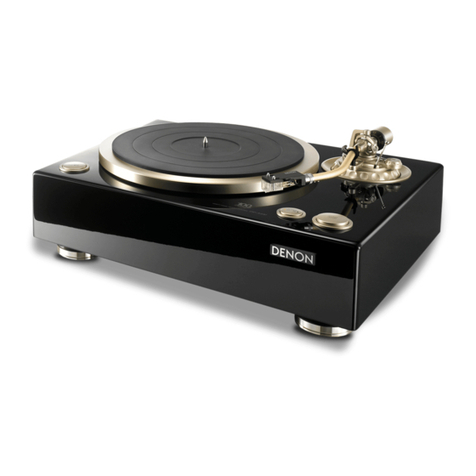
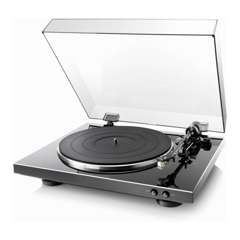
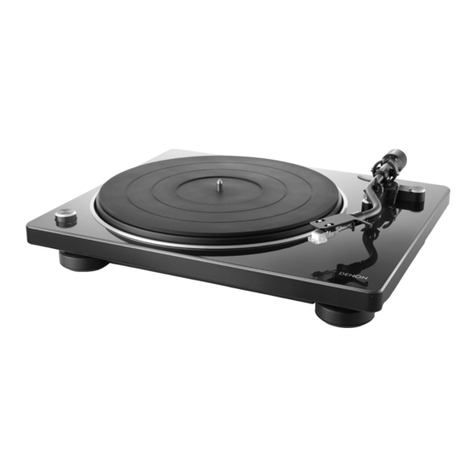
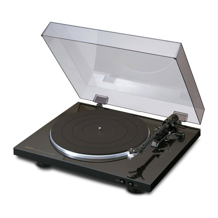
Denon DP-A100 User manual

Deze download wordt u aangeboden door Pick-upnaalden.nl
Fazantendreef 17-19
8251 JR Dronten
T: 0321 769022
W: www.pickupnaalden.com
W: www.pickupnaald.com
Facebook: www.facebook.com/pickupnaalden
Twitter: twitter.com/Pickupnaalden
Google+ : plus.google.com/114738445546162436900

D&M Holdings Inc.
SERVICE MANUAL
e
e
Copyright 2010 D&M Holdings Inc. All rights reserved.
WARNING: Violators will be prosecuted to the maximum extent possible.
MODEL JP E3 E2 EK EA E1 E1K E1C
DP-A100
33
DIRECT DRIVE TURNTABLE SYSTEM
Ver. 3
•Some illustrations using in this service manual are slightly different from the actual set.
•Please use this service manual with referring to the operating instructions without fail.
•For purposes of improvement, specifications and design are subject to change without notice.
S0171-1V03DM/DG1010
Please refer to the
MODIFICATION NOTICE.

2
SAFETY PRECAUTIONS
The following check should be performed for the continued protection of the customer and service technician.
LEAKAGE CURRENT CHECK
Before returning the unit to the customer, make sure you make either (1) a leakage current check or (2) a line to chassis
resistance check. if the leakage current exceeds 0.5 milliamps, or if the resistance from chassis to either side of the
power cord is less than 460 kohms, the unit is defective.
Be sure to test for leakage current with the AC plug in both polarities, in addition, in each power ON, OFF and STANDBY
mode, if applicable.
CAUTION Please heed the points listed below during servicing and inspection.
◎Heed the cautions!
Spots requiring particular attention when servicing, such
as the cabinet, parts, chassis,etc., have cautions indicated
on labels. be sure to heed these causions and the
cautions indicated in the handling instructions.
◎Caution concerning electric shock!
(1) An AC voltage is impressed on this set, so touching
internal metal parts when the set is energized could
cause electric shock. Take care to avoid electric
shock, by for example using an isolating transformer
and gloves when servicing while the set is energized,
unplugging the power cord when replacing parts, etc.
(2) Tere are high voltage parts inside. Handle with extra
care when the set is energized.
◎Caution concerning disassembly and
assembly!
Through great care is taken when manufacturing parts
from sheet metal, there may in some rare cases be burrs
on the edges of parts which could cause injury if fingers
are moved across them. Use gloves to protect your hands.
◎Only use designated parts!
The set's parts have specific safety properties (fire
resistance, voltage resistance, etc.). For replacement
parts, be sure to use parts which have the same
poroperties. In particular, for the important safety parts
that are marked z on wiring diagrams and parts lists, be
sure to use the designated parts.
◎Be sure to mount parts and arrange the wires
as they were originally!
For safety seasons, some parts use tape, tubes or other
insulating materials, and some parts are mounted away
from the surface of printed circuit boards. Care is also
taken with the positions of the wores omsode amd clamps
are used to keep wires away from heating and high
voltage parts, so be sure to set everything back as it was
originally.
◎Inspect for safety after servicing!
Check that all screws, parts and wires removed or
disconnected for servicing have been put back in their
original positions, inspect that no parts around the area
that has been serviced have been negatively affected,
conduct an inslation check on the external metal
connectors and between the blades of the power plug,
and otherwise check that safety is ensured.
(Insulation check procedure)
Unplug the power cord from the power outlet, disconnect
the antenna, plugs, etc., and turn the power switch on.
Using a 500V insulation resistance tester, check that the
inplug and the externally exposed metal parts (antenna
terminal, headphones terminal, input terminal, etc.) is
1MΩor greater. If it is less, the set must be inspected and
repaired.
Many of the electric and structural parts used in the set
have special safety properties. In most cases these
properties are difficult to distinguish by sight, and using
replacement parts with higher ratings (rated power and
withstand voltage) does not necessarily guarantee that
safety performance will be poreserved. Parts with safety
properties are indicated as shown below on the wiring
diagrams and parts lists is this service manual. Be sure to
replace them with parts with the designated part number.
(1) Schematic diagrams ......Indicated by the z mark.
(2) Parts lists ......Indicated by the zmark.
Using parts other than the designated
parts could result in electric shock, fires
or other dangerous situations.
CAUTION Concerning important safety
parts
3
NOTE FOR SCHEMATIC DIAGRAM
WARNING:
Parts marked with this symbol zhave critical characteristics. Use ONLY replacement parts recommended by the manufacturer.
CAUTION:
Before returning the unit to the customer, make sure you make either (1) a leakage current check or (2) a line to chassis resistance check. If the
leakage current exceeds 0.5 milliamps, or if the resistance from chassis to either side of the power cord is less than 460 kohms, the unit is defective.
WARNING:
DO NOT return the unit to the customer until the problem is located and corrected.
NOTICE:
ALL RESISTANCE VALUES IN OHM. k=1,000 OHM / M=1,000,000 OHM
ALL CAPACITANCE VALUES IN MICRO FARAD. P=MICRO-MICRO FARAD EACH VOLTAGE AND CURRENT ARE MEASURED AT NO SIGNAL
INPUT CONDITION. CIRCUIT AND PARTS ARE SUBJECT TO CHANGE WITHOUT PRIOR NOTICE.
Parts for which "nsp" is indicated on this table cannot be supplied.
When ordering of part, clearly indicate "1" and "I" (i) to avoid mis-supplying.
Ordering part without stating its part number can not be supplied.
Not including General-purpose Carbon Chip Resistor in the P.W.Board parts list. (Refer to the Schematic Diagram for those parts.)
Parts marked with this symbol zhave critical characteristics. Use ONLY replacement parts recommended by the manufacturer.
Not including General-purpose Carbon Film Resistor in the P.W.Board parts list. (Refer to the Schematic Diagram for those parts.)
Part indicated with the mark "★" is not illustrated in the exploded view.
WARNING:
1.
2.
3.
4.
5.
6.
●Resistors
RD : Carbon
RC : Composition
RS : Metal oxide film
RW: winding
RN : Metal film
RK : Metal mixture
P : Pulse-resistant type
NL : Low noise type
NB : Non-burning type
FR : Fuse-resistor
F : Lead wire forming
2B : 1/8 W
2E : 1/4 W
2H : 1/2 W
3A : 1 W
3D : 2 W
3F : 3 W
3H : 5 W
F:±1%
G:±2%
J:±5%
K:±10%
M:±20%
Ex.: RN
Type
14K
Shape
and per-
formance
2E
Power
182
Resist-
ance
G
Allowable
error
FR
Others
*Resistance
1800ohm=1.8kohm1 8 2
Indicates number of zeros after effective number.
2-digit effective number.
1.2ohm1 R 2
2-digit effective number, decimal point indicated by R.
1-digit effective number.
: Units: ohm
●Capacitors
CE : Aluminum foil
electrolytic
CA : Aluminium solid
electrolytic
CS : Tantalum electrolytic
CQ : Film
CK : Ceramic
CC : Ceramic
CP : Oil
CM: Mica
CF : Metallized
CH : Metallized
HS : High stability type
BP : Non-polar type
HR : Ripple-resistant type
DL : For change and discharge
HF : For assuring high requency
U : UL part
C : CSA part
W : UL-CSA part
F : Lead wire forming
0J : 6.3 V
1A : 10 V
1C : 16 V
1E : 25 V
1V : 35 V
1H : 50 V
2A : 100 V
2B : 125 V
2C : 160 V
2D : 200 V
2E : 250 V
2H : 500 V
2J : 630 V
F:±1%
G:±2%
J:±5%
K:±10%
M:±20%
Z:±80%
: - 20%
P : +100%
C:±0.25pF
D:±0.5pF
= : Others
Ex.: CE
Type
04W
Shape
and per-
formance
1H
Dielectric
strength
3R2
Capacity
M
Allowable
error
BP
Others
・Units:μF.
2200μF2 2 2
Indicates number of zeros after effective number.
2-digit effective number. ・Units:μF.
2.2μF2 R 2
2-digit effective number, decimal point indicated by R
1-digit effective number.
*Capacity (electrolyte only)
・When the dielectric strength is indicated in AC,"AC" is included after the dieelectric strength value.
*Capacity (except electrolyte)
・Units:pF
2200pF=0.0022μF2 2 2
Indicates number of zeros after efective number. (More than 2)
2-digit effective number. ・Units:pF
220pF2 2 1
2-digit effective number.
Indicates number of zeros after effective numver. (0 or 1)
NOTE FOR PARTS LIST

4
TECHNICAL SPECIFICATIONS
210
515 max
72
490
320
320
387
465 max
14
53.5 280 53.5
10530 75
nTurntable section
Driving system : Servo system direct drive
Speed : 33–1/3rpm, 45rpm
Wow & flutter : Less than 0.1 % WRMS
Starting time : Specified speed within 0.3 sec (for 33 rpm)
Turntable : Aluminum die-cast, 331 mm (13-1/32”) in diameter
Motor : Direct-drive motor
Speed control system : Quartz control
Load characteristics : 0 % with the stylus pressure 80 g (2.8 oz)
Speed deviation : Within ± 0.003 %
nTone arm section
Arm form : Static balance S-shaped pipe arm
Effective arm length : 244 mm (9-39/64”)
Overhang : 14 mm (35/64”)
Tracking error : within 3°
Arm height adjustable range : about 6 mm (15/64”)
Stylus pressure variable range : 0 to 4.0 g (0.14 oz)
One step 0.1 g
Suitable cartridge empty weight : 4 to 10 g (0.14 oz to 0.35 oz)
Head shell weight :
18 g (0.63 oz, including screws, nuts, nylon washers)
Cartridge spacer weight : 0.25 g (0.01 oz, 1 sheet)
nTotal
Power supply : AC 120 V, 60 Hz
Power consumption : 10 W
Maximum external dimensions :
With dust cover closed:
490 (W) ×213 (H) × 405 (D) mm (19-19/64” x 8-25/64” x 15-15/16”)
With dust cover open:
490 (W) ×515 (H) × 465 (D) mm (19-19/64” x 20-9/32” x 18-5/16”)
Weight : 15.7 kg (0.55 oz)
nCartridge (DL-A100)
Power generation method : Moving coil (MC) type
Output voltage : 0.3 mV (1 kHz 50 mm/sec horizontally)
Channel balance : within 1 dB (1 kHz)
Channel separation : more than 25dB (1 kHz)
Impedance : 40 Ω ± 20 %
Compliance : 5 × 10⁻⁶ cm/dyne (used 100 Hz record)
Stylus tip : 0.2 mm (1/64”) square solid diamond
Stylus pressure : 2.5 g ± 0.3 g (0.09 oz ± 0.01 oz)
Frequency response : 20 Hz to 45 kHz
Weight : 8.8 g (0.31 oz)
Load resistance : more than 100 Ω (40 Ω when a transformer is used)
Maximum external dimensions :
15 (W) × 15 (H) × 26.8 (D) mm (19/32” x 19/32” x 1-1/16”)
DIMENSION

5
DISASSEMBLY
• Follow the procedure below in reverse order when reassembling.
• If wire bundles are untied or moved to perform adjustment or parts replacement etc., be sure to rearrange them neatly
as they were originally bundled or placed afterward.
Otherwise, incorrect arrangement can be a cause of noise generation.
1. Platter
(1) Detach the rubber mat to the arrow direction.
(2) Put a finger through the round hold in the platter and lift straight up to remove the platter.
2. Bottom Cover
(1) Place the set upside down so that the tone arm base does not hit the installation rack and so that the cabinet does
not get scratched.
(2) Remove 9 screws from the bottom side.
(3) Detach the Bottom Cover to the arrow direction.

6
3. Main P.W.B. unit and Tone Arm Base
(1) Remove 4 screws qfrom the Main P.W.B. unit.
(2) Remove the soldering from the tone arm signal wire connected to the output board. When assembling, solder as
indicated on the wiring diagram.
(3) Holding the tone arm base down, remove the 3 screws efixing the tone arm base.
4. Motor unit P.W.B and Power Trans
(1) Remove 5 screws efrom the Motor unit P.W.B..
(2) Remove the soldering from the ground wire connecting the Motor unit P.W.B. and output board.
(3) Turn the set upside down.
(4) Holding the motor unit board down, remove the 4 screws rfixing the Motor unit P.W.B..
(5) Holding down the nuts t, remove the 4 screws yfixing the transformer.
q
w
e
r
y
tt

7
5. KNOB ASS'Y
(1) Remove the 2 screws ueach fixing the KNOB ASS'Y fixing plate.
(2) Remove the 3 screws ieach fixing the 33/45 unit P.W.B..
(3) Pull out the KNOB ASS'Y fixing plate and remove the KNOB ASS'Y.
u
u
u
i

8
ADJUSTMENT
Electrical Adjustment for Wow and Flutter
(1) Detach the turntable and turn over the set.
(2) Open the bottom cover.
(3) Connect a digital volt meter or tester to CN104 (3P) on the Motor P.W.B..
(4) Turn on the power. Set the speed to 33 rpm.
(5) Insert a screwdriver into R134 (variable resistor) and adjust so that the absolute values of the two digital volt meters
or testers are closest.
CN104
R134
Digital volt meter
or Tester
(1)
Digital volt meter
or Tester
(2)
CN104
①
②
③
Motor+
GND
Motor-

9
BLOCK DIAGRAM

10
WIRING DIAGRAM
GND PCB
MAIN PCB
D.D MOTOR PCB
33/45 PCB
CN301
11 P
CN901
C901
C909
CN303
CN302
BA
POWER PCB
CN1

11
PRINTED WIRING BOARDS
鉛フリー半田
半田付けには、鉛フリー半田 (Sn-Ag-Cu) を使用してください。
Lead-free Solder
When soldering, use the Lead-free Solder (Sn-Ag-Cu).
MAIN P.W.B. UNIT
FOIL SIDE COMPONENT SIDE
COMPONENT SIDE COMPONENT SIDE
COMPONENT SIDE
OUTPUT P.W.B. UNIT 33/45 P.W.B. UNIT AC P.W.B. UNIT
START/STOP P.W.B. UNIT

12
鉛フリー半田
半田付けには、鉛フリー半田 (Sn-Ag-Cu) を使用してください。
Lead-free Solder
When soldering, use the Lead-free Solder (Sn-Ag-Cu).
D.D. MOTOR P.W.B. UNIT
FOIL SIDE
COMPONENT SIDE

C101 102P
R101 6.8K
D101
D102
R102
680
IC101B
NJM2147
R103
560K
D106
1SS133
D105
1SS133
D104
1SS133
D103
1SS133
R106
270
R107 22K
R105 270 R104
22K
C103 102P
R122 1 1W
C102 102P
C114
100u/35
C115
100u/35
C104 102P
R108
6.8K
D107
1SS133
D108
1SS133
R109
680
IC101A
NJM2147
R110
560K
D112
1SS133
D111
1SS133
D110 1SS133
D109 1SS133
R113
270
R114
22K
R111
270
R112
22K
C106
102P
C105
102P
C107 102P
R115 6.8K
D113
1SS133
D114
1SS133
R116
680
IC102B
NJM2147
R117
560K
D118 1SS133
D117 1SS133
D116
1SS133
D115
1SS133
R120
270
R121
22K
R118
270
R119
22K
C109 102P
C108
102P
C118
100u/35
C119
100u/35
IC106C
BU4066
IC106D
BU4066
IC106B
BU4066
CN103
11P
IC104A
4580
R126
680K
R125
10K R127
18K R131
22K
R132
22K
C120
0.1uF
R133
12K
R135
2.7K
R134
4.7K
IC104B
4580
R128
10K
R129
680K
R130
18K
C121
0.1uF
R136 18K
R137 18K
IC105B
4580
IC105A
4580
R138
18K
R140 22K
R141 47K
R139
22K
R142
22K
R143
22K
D119
1SS133
R144
1K
R145
1K
D120
Z5.1B
D121
Z5.1B
C123
100u/10
C122
100u/10
TO IC106 P7
TO IC106 P14
C909
2200u/35
C910
2200u/35
IC905
NJM7815
IC906
NJM7915
C916
0.1u
C919
0.1u
C915
100u/25
C917
100u/25
C908
0.1u/AC125
MO1
YMOTOR
C112
0.1uF
C113
0.1uF
C110
0.1uF
C111
0.1uF
C117
100uF/35
C116
100uF/35V
Q101
DTC124TS
Q102
DTA124TS
D908
1N4002
D907
1N4002
D906
1N4002
D905
1N4002
CN901
5P
C912
0.1u
C914
0.1u
C124
0.1u
C127
0.1u
C129 0.1u
C131
0.1u
C130
100u/25
C128
100u/25
C126
100u/25
C125
100u/25
C132
0.1u
C133
0.1u
LA
LC
LOCK
GND
HA
HB
HC
H11
US1881KUA
H12
US1881KUA
H13
US1881KUA
CHB
CHA
IC103
HEDS9700F51
5V
Q104
2SB1340
Q106
2SB1340
Q103
2SD1889
R146 1 1W
Q105
2SD1889
Q107
2SD1889
Q108
2SB1340
R123
1 1W
R147 1 1W
R148 1 1W
R124
1 1W
C134
100u/35
C135
100u/35
C137
100u/35
C136
100u/35
IC903
NJM7824
IC904
NJM7924
C907
0.1u/AC125
C913
100u/35
C911
100u/35
R149
10K
R151 1K
R150 1K
R152 1K
C140
1000P
C139
1000P
C141
1000P
R154
220
R155
220
R153
220
IC901
NJM7805
D903
1N4002
D904
1N4002
D901
1N4002
D902
1N4002
C904
100u/16
C901
1000u/35
IC902
NJM7812
C905
100u/10
C906
L901
FB
C138
0.1u
CN104
3p
CN903
4P
F02
F1.25A
F03
F1.25A
C918
0.1u/AC125
CN903A
CON4
IN
GND
12V
5V
405-TT300-753
WHITE
RED
R
L
RED
GRN
BLE
WHI
L CH (WHITE)
R CH (RED)
BLK
CARTRIDGE
BLK GND
G
405-A100-2781
F04
1.5A
C2
0.1u
C1
0.1u
1SS133
1SS133
-15V
5V
-15V
15V
-15V
15V-15V
15V
24V
-24V
15V
-15V
5V
5V
12V
12V
5V
+
5
-
6
7
84
+
3
-
2
1
84
+
5
-
6
7
84
89
6
1011
12
34
5
1
2
3
4
5
6
7
8
9
10
11
+
3
-
2
1
84
+
5
-
6
7
84
+
5
-
6
7
84
+
3
-
2
1
84
IN 3
2
OUT
1
GND
Vin 2
GND
3
OUT
1
BC
A
1
2
3
4
5
VCC
1
GND
2
OUT
3
VCC
1
GND
2
OUT
3
VCC
1
GND
2
OUT
3
GND
1
CHA
2
VCC
3
CHB
4
IN 3
2
OUT
1
GND
Vin 2
GND
3
OUT
1
IN 3
2
OUT
1
GND IN 3
2
OUT
1
GND
0.1u
1
2
3
1
2
3
4
1
2
3
4
AC IN
F01
T1AL 250V
F1
FILTER
C01
0.01uFX2
SW1
C034700PF T1
1
2
3
4
5
CN901
5P
1
2
CN1
2P
C02
4700P
405-1300-1048
405-1300-1106B
F01 T1AL 250V
EU
T500mAL 250V
USA/JP
87654321
A
B
C
D
E
F
SCHEMATIC DIAGRAMS (1/2)
D.D MOTOR UNIT
AC POWER UNIT
DC UNIT
13

HA
VCL
1
PB0
2
PB1
3
PB2
4
PB3
5
PB4
6
PB5
7
PB6
8
PB7
9
RESO
10
VSS
11
P90
12
P91
13
P92
14
P93
15
P94
16
P95
17
D0/P40
18
D1/P41
19
D2/P42
20
D3/P43
21
VSS
22
D4/P44
23
D5/P45
24
D6/P46
25
D7/P47 26
D8 27
D9 28
D10 29
D11 30
D12 31
D13 32
D14 33
D15 34
VCC 35
A0 36
A1 37
VSS 44
VSS 57
P60/WAIT 58
P61/BREQ 59
P62/BACK 60
P67/ 61
STBY 62
RES 63
NMI 64
VSS 65
EXTAL 66
XTAL 67
VCC 68
AS 69
RD 70
HWR 71
LWR 72
MD0 73
MD1 74
MD2 75
AVCC
76
VREF
77
P70/AN0
78
P71/AN1
79
P72/AN2
80
P73/AN3
81
P74/AN4
82
P75/AN5
83
P76/AN6/DA0
84
P77/AN7/DA1
85
AVSS
86
IRQ0/P80
87
CS3/IRQ1/P81
88
CS2/IRQ2/P82
89
ADTRG/CS1/IRQ3/P83
90
CS0/P84
91
VSS
92
TCLKA/TP0/PA0
93
TCLKB/TP1/PA1
94
TCLKC/TIOCA0/TP2/PA2
95
TCLKD/TIOCB0/TP3/PA3
96
A23/PA4
97
A22/PA5
98
A21/PA6
99
A20/PA7
100
A2 38
A3 39
A4 40
A5 41
A6 42
A7 43
A8 45
A9 46
A10 47
A11 48
A12 49
A13 50
A14 51
A15 52
A16 53
A17 54
A18 55
A19 56
IC303
MAX003
5V
C320
0.1uF
5V
C309
1u/50
C311
100u/10
R317
4.7K
C310
0.1uF
C313
15P
C312
18P
R322
1M
R321
100
X301
16MHz
C316
0.1uF
R318 4.7K
R319 4.7K
R320 4.7K
D305
1SS132
C317
0.1uF
L303 FB
L302
FB
1A0
1A1
1A2
1A3
1A4
1A5
1A6
1A7
1A8
1A9
1A10
1A11
1A12
1A13
1A14
1A15
1A0
1A1
1A2
1A3
1A4
1A5
1A6
1A7
1A8
1A9
1A10
1A11
1A12
1A13
1A14
1A15
1D0
1D1
1D2
1D3
1D4
1D5
1D6
1D7
1D0
1D1
1D2
1D3
1D4
1D5
1D6
1D7
C315
0.1uF
A15
1
A12
2
A7
3
A6
4
A5
5
A4
6
A3
7
A2
8
A1
9
A0
10
Q0
11
Q1
12
Q2
13
GND
14
Q3 15
Q4 16
Q5 17
Q6 18
Q7 19
CE 20
A10 21
OE 22
A11 23
A9 24
A8 25
A13 26
A14 27
VCC 28
IC304
W27E512DIP
C301
1000P
R301
10K
D301
1SS132
D302
1SS132
C302
0.1uF
R302
22K
R303
22K
R304
3.3K R305 1M
R308 47K
5V
R307
100
R306
1K
C303
0.1uF
C304
1000P
R309
10K
D303
1SS132
C305
0.1uF
R310
22K
R311
22K
R312
3.3K
R313
1M
R316 47K
R315
100
R314
1K
C306
0.1uF
C307
0.1uF
C308
100u/10
+
3
-
2
1
84
IC302A
BA10393
+
5
-
6
7
84
IC302B
BA10393
D304
1SS132
C318
0.1uF
C319
100u/10
D306
1SS132
5V L301
FB
L304 FB 1CE
1CE
1OE
1OE
5V
C314
100u/10
R324 220
5V
R328 220
R323 220
HB
HC
CHB
CHA
5V
LA
LC
LOCK
1
2
3
4
5
6
7
8
9
10
11
CN302
11P
NC
1
SUB
2
GND
3VO 4
VCC 5
IC301
BD4745G
5V
SW202
PL/ST
SW201
33/45 1
2
3
4
CN201
4P
LA
LC
LOCK
HC
HB
HA
CHA
CHB
GND
5V
12V
R327
10K
R329
470
R330
470
R326
220
Q301
2SC1740
Q302
2SC1740
1
2
3
4
CN301
4P
1
2
CN303
2P
R325 220
1
2
CN202
2P
33LED
45LED
33/45
PL/ST
33LED
45LED
33/45
GND
GND
R331 10K
R332 10K
R333 10K
D202
45
D201
33
5V
MAIN UNIT
33/45 UNIT
START/STOP UNIT
87654321
A
B
C
D
E
F
SCHEMATIC DIAGRAMS (2/2)
MAIN UNIT
33/45 UNIT
START/STOP UNIT
14

15
EXPLODED VIEW s
Parts marked with this symbol have critical
characteristics.
Use ONLY replacement parts recommended by
the manufacturer.
WARNING:
3
1
2
5
9
10
10
11
12
13 44
11
46
14
41
43
43
15
68
16
17
18
45
46
42
19
19
20
20
20
21
21
22
23 23
24
24
24
25
27
28
88
28
88
29
47
30
31
76
76
35
31
33
70
36
34
74
81
70
23
23
37 39
39
39
39
53
94
40
37
39
39
59
23
23
33
39
96
48
50
69
49
54 23
51
55
56
91
60
60
60
60
60
75
75
75
75
62
62
62
62
62
62
63
63
64
65
64
65
64
64
66
71
71
71
77
77
77
77
77
42
42
93
52
97
99
98
87
19
95
94
102
!
!
!
for E2
for E3
!
!
!!
92

16
POINTS OF GREASING s
3
1
2
5
9
10
13
44
11
46
14
41
43
43
15
68
16
17
18
45
46
42
19
19
20
20
20
21
21
22
23 23
24
24
24
25
27
28
88
28
88
29
47
30
31
76
76
35
31
33
70
36
34
81
70
23
23
37 39
39
39
39
53
94
40
37
39
39
59
23
23
33
39
96
48
50
69
49
54 23
51
55
56
91
60
60
60
60
60
75
75
75
75
62
62
62
62
62
62
63
63
64
65
64
65
64
64
66
71
71
71
77
77
77
77
77
42
42
93
52
11
11
12
97
99
98
87
19
95
94
102
!
!
Maker NoteGrease
CR-S
KF-96H
Daizo Corporation (Nichimoly)
Shin-Etsu Chemical Co., Ltd.
Synthetic oil based resin-use lithium grease
Dimethyl silicone fluid 100.000mm
2
/s
Grease:CR-S
Shaft all area
(4.0mg <Φ2> each X 2 )
Shaft all area
(4.0mg <Φ2> each X 2 )
Grease:CR-S
Grease:CR-S
( 4.0mg <Φ2> )
Grease:CR-S
Around inner of indicator
(no leakage on the sueface)
Around inner of indicator
(no leakage on the sueface)
( 15mg <Φ3> 㧕
Grease:KF-96H
( 30mg <Φ3.5> )
Shaft all area
92

17
PARTS LIST OF EXPLODED VIEW s
zParts for which "nsp" is indicated on this table cannot be supplied.
z
P.W.B. ASS'Y for which "nsp" is indicated on this table cannot be supplied. When repairing the P.W.B. ASS'Y, check the board parts table and order replacement parts.
zPart indicated with the mark " ★" is not illustrated in the exploded view.
zThe parts listed below are for maintenance only, might differ from the parts used in the unit in appearances or dimensions.
Note: The symbols in the column "Remarks" indicate the following destinations.
E3 : U.S.A. & Canada model E2 : Europe modell
Ref. No. Part No. Part Name Remarks Q'ty New
A 941401004130D CABINET&BOTTOMASSY DPA100 703-A100-1314 1 *
1 nsp CHASSIS ASSY -
2 nsp BOTTOM BASE ASSY -
3 00D9410026206 ALUMINUM PLATTER ASSY 702-1300-041 1
5 00D9410015204 SLIPMAT PACKING ASSY 705-500-867 1
9 00D9410027001 POWER BUTTON 701-1300-2920 1
10 nsp BUTTON FRAME 100-1300-2094 2
11 nsp SCREW 602-2002-085 4
z12 00D9410015505 POWER SW 403-1300-180 1
13 00D9410027205 START/STOP BUTTON 701-1300-2919 1
14 00D9410015806 PUSH SW 403-1300-181 1
15 00D9410027302 33/45 BUTTON 701-1300-2923 1
16 nsp SPRING FOR BUTTON 603-500-289 1
17 nsp 33/45 BUTTON FRAME 701-1300-2921 1
18 nsp E-RING WASHER 606-F200-011 1
19 nsp SHIELDING PLATE FOR BUTTON 300-5500-1006 3
20 nsp SCREW 602-1300-474 6
21 nsp SCREW 602-500-471 4
22 nsp MOTOR FIXING METAL PLATE 300-5500-1007 1
23 nsp SCREW 602-500-469 12
24 nsp SCREW 602-500-470 4
z25 941101003520D TRANSFORMER (E2) E2 411-A100-813 1 *
z25 941101003510D TRANSFORMER (E3) E3 411-A100-812 1 *
27 nsp FUSE LABEL E2 501-PRODJ2-1298 1
27 nsp FUSE LABEL E3
501-PRODJ2-1298A
1*
28 nsp HINGE ASSY 703-1300-757A 2
29 nsp SCREW 602-KMD510-161 2
30 nsp MAIN PCB ASSY 704-1300-4436 1
81 00D9410026002 DUST COVER ASSY 701-1300-2924 1
31 nsp HINGE FIXING PLATE 300-5500-1008A 2
33 nsp SCREW 602-1300-468 4
35 nsp DUST COVER 701-1300-2121 1
36 nsp DECORATIVE PLATE FOR DUST COVER 501-5500-1661 1
70 nsp BUSHING 604-1300-285 2
76 nsp NUT 601-1300-023 4
34 941409003420D COUNTER WEIGHT ASSY 702-A100-069 1 *
37 nsp FIXING PILLAR 200-1300-347 3 *
39 nsp MAT RUBBER 604-5500-269 9
40 941306003570D TONEARM ASSY 704-A100-9420 1 *
41 941306003560D MOTOR ASSY 704-A100-9423 1 *
42 nsp SCREW 602-1300-472 8
43 nsp SCREW 602-1300-476 5
44 nsp DC PCB ASSY 704-1300-4437 1
45 nsp 33/45 PCB ASSY 704-1300-4438 1
46 nsp SCREW 602-B600-057 3
z47 nsp AC PCB ASSY E2 704-A100E2-9440 1 *
d
d
d

18
Ref. No. Part No. Part Name Remarks Q'ty New
z47 nsp AC PCB ASSY E3 704-A100E3-9537 1 *
48 nsp SHEET 501-5500-1666 1
49 nsp SCREW 602-2002-085 3
50 nsp AC CORD FIXING PLATE 300-5500-1005 1
51 nsp RCA FIXING PLATE 703-A100-1312 1 *
52 nsp GND PCB ASSY 704-A100-9422 1 *
53 nsp BRACKET(L TYPE) 300-HDJ7000-472 2
54 nsp GROUND PIN 200-DJ100-231 1
55 nsp WASHER 606-Q2221-122 1
56 nsp SCREW 602-2002-085 2
59 nsp ADHESIVE BACKED MOUNT 504-HDJ7000-032 2
60 nsp SCREW 602-1300-475 9
62 nsp PCB FIXING PILLAR 200-500-346 11
63 nsp TRANSFORMER FOR FIXING PILLAR 200-ST150-332 4
64 nsp WASHER 606-ST150-157 8
65 nsp NUT 601-F200-001 4
66 nsp RATING LABEL (E2) E2 502-A100E2-2373 1 *
66 nsp RATING LABEL (E3) E3 502-A100E3-2373 1 *
68 00D9410018803 LENS 100-5500-2098 2
z69 941641003530D 2P AC JACK 420-4001-221 1 *
71 nsp SCREW 602-500-477 3
z74 00D2062215006 VFS AC CORD (E2) E2 409-A100-209 1
z74 00D2062220004 VFS AC CORD (E3) E3 409-A100-208 1
75 00D9410029805 FOOT ASS'Y 701-1300-2927 4
77 00D9410029711 WASHER 606-1300-117 9
87 941409003430D
705A100E21448 HEADSHELLASSYDPA100 ACD-50
705-A100E2-1448 1 *
88 nsp DECORATION FOR HINGE 501-1300-1708A 2
91 nsp NUT 601-A100-004 1
92 nsp 1P LEAD WIRE 406-1300-698 1
93 nsp GROUNDING METAL NET 407-DJ1900-094 1
94 00MYT02011280 VFS RCA PIN JACK (RED) 420-A100-346 1
95 00MYT02011290 VFS RCA PIN JACK (WHITE) 420-A100-347 1
96 nsp VFS CARTRIDGE(DL-A100) 402-A100-100 1
97 941421003660D DENON BADGE 501-A100-2363 1 *
z98 nsp 1P WIRE (L50,RED) 406-A100-1152 1 *
z99 nsp 1P WIRE (L50,YEW) 406-A100-1153 1 *
★100 nsp CAUTION LABEL 501-A100E2-2380 1 *
★101 nsp FCC LABEL E3 501-A100E3-2382 1 *
102 nsp BOTTOM CAUTION LABEL E3 501-A100E3-2381 1 *
OPTION COUNTER WEIGHT sd
Ref. No. Part No. Part Name Remarks Q'ty New
(34) 941409004140D 200A100630 WEIGHT HEAVY DPA100 ACD-49 200-A100-630 1 *
(34) 941409004150D 200A100629 WEIGHT LIGHT DPA100 ACD-48 200-A100-629 1 *
d
d

19
PACKING VIEW s
16
18
2
15
3
7
4
5
6
20
21
22
23
23
20
14
14
1
-1~7
-1~2
11
-1~2
13
-1~7
12
-1~2
9-1~2
10
for E3
10
10
for E2
-1~2
8-1~3
-1 1-3
1-4
1-2
17-1~3
19
Other manuals for DP-A100
2
Table of contents
Other Denon Turntable manuals

Denon
Denon DP-300F User manual

Denon
Denon DP-37F User manual

Denon
Denon DP-6700 User manual

Denon
Denon DP-500M User manual

Denon
Denon DP-450USB User manual

Denon
Denon DP-200USB User manual

Denon
Denon DP-47F User manual

Denon
Denon DP-67L User manual

Denon
Denon DP-29F User manual

Denon
Denon DN-SC3900 User manual

Denon
Denon DN-S3700 User manual

Denon
Denon DP-29F User manual

Denon
Denon DP-47F User manual

Denon
Denon DN-C615 User manual

Denon
Denon DP-A100 User manual

Denon
Denon DP-200USB User manual

Denon
Denon DP-200USB User manual

Denon
Denon DP-35F User manual

Denon
Denon DP-37F User manual

Denon
Denon DL-103R User manual