aXcs
®
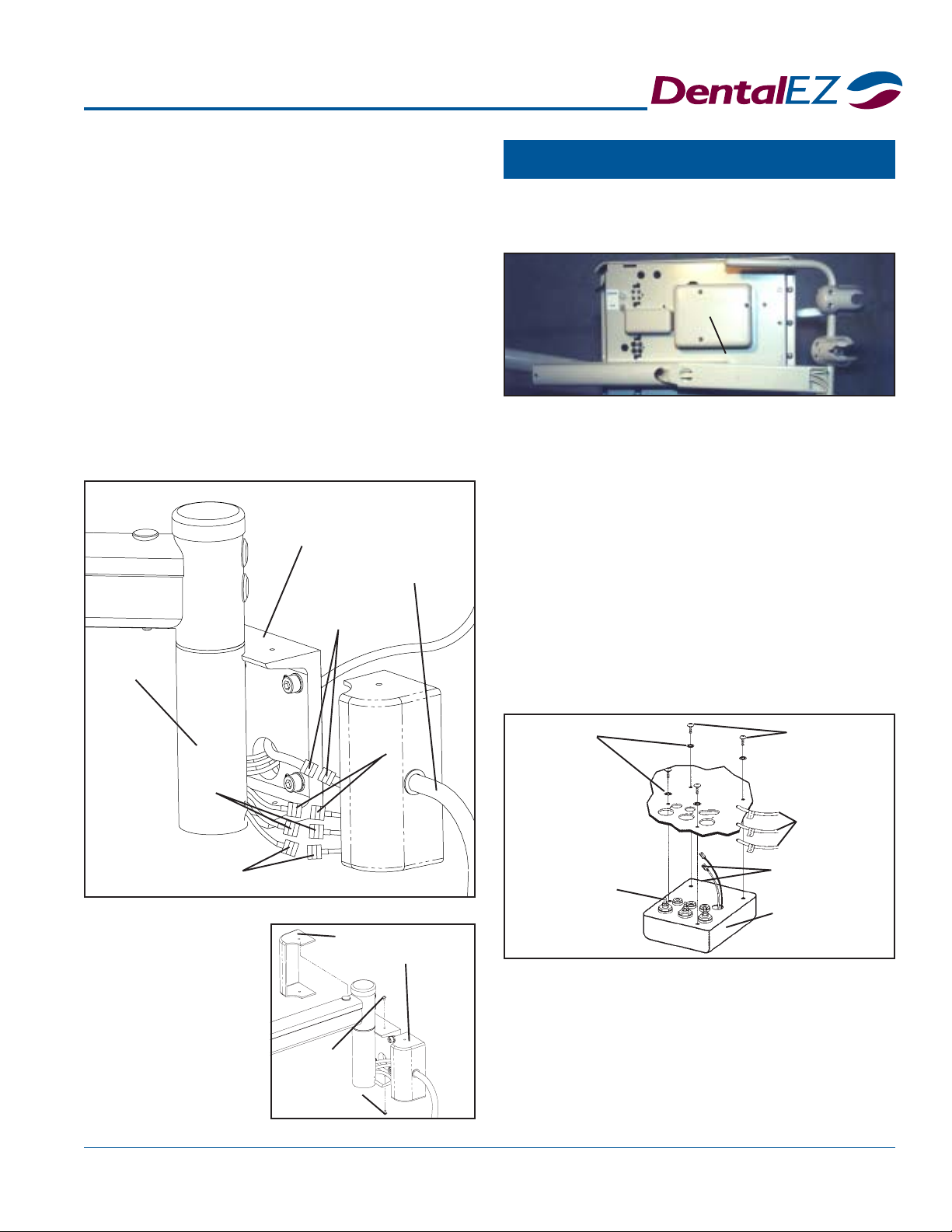
Wall/Cabinet Unit 19
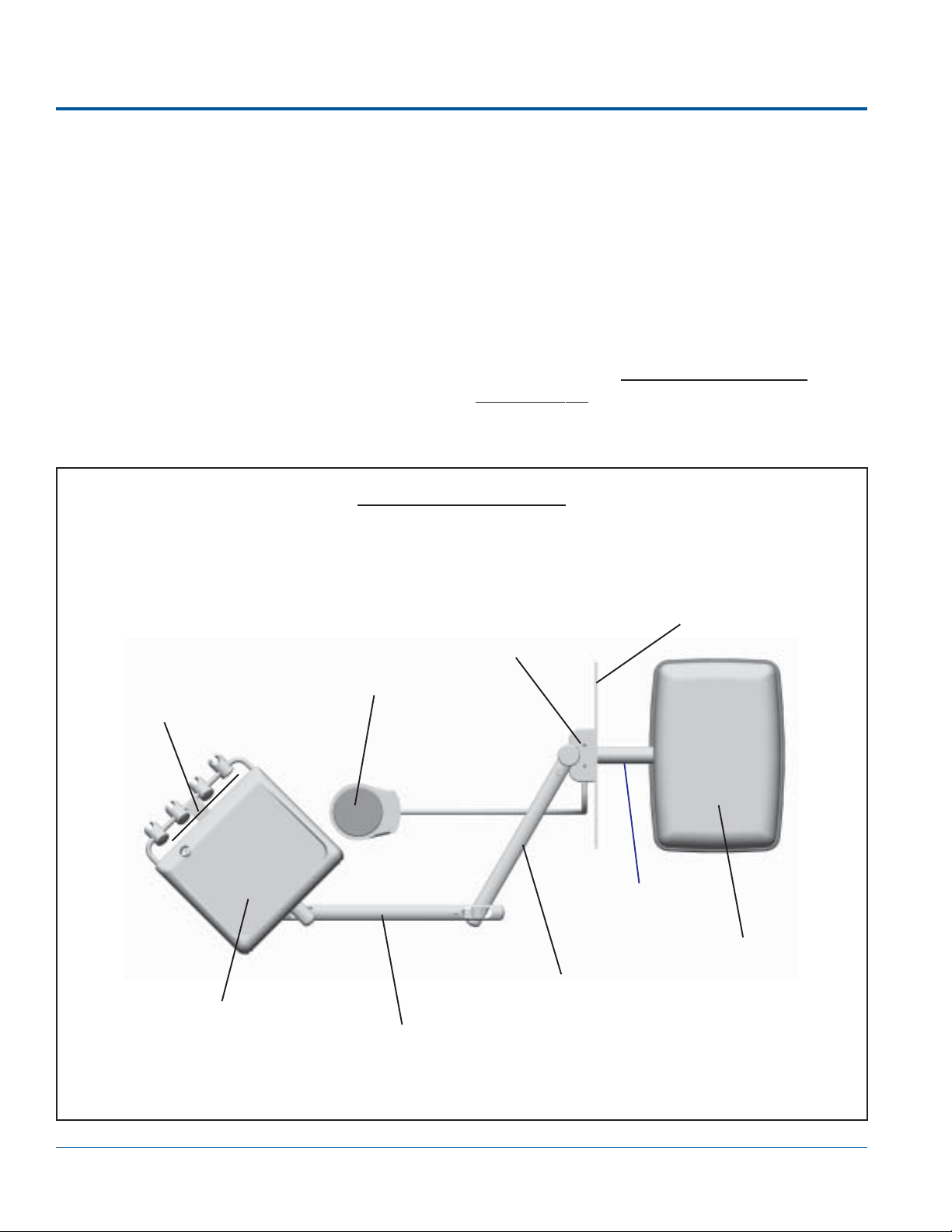
Flush Toggle
Optional
Chipblower
WET/DRY
Toggle Valve
Disk
Section V Operation
FLUSH to le, located at the rear of the
2. While operatin the handpiece, turn the valve
counterclockwise to increase the volume of
coolant water spray. To decrease the volume,
turn the valve clockwise.
Air Pressure
Air pressure to each handpiece can be adjusted to the
manufacturer's specifications by followin the air
pressure instructions in Section IV Testin , Page 17.
NOTE: These procedures must be done while:
The master switch is in the ON position,
The handpiece is out of its holder and
The foot control is fully depressed.
NOTE: When making necessary air pressure adjust-
ments, refer to the air pressure gauge located at the front
of the delivery head to check the approximate amount
of air pressure delivered to the handpiece.
Flush System
It is recommended that the tubin of each handpiece
used be flushed after each patient.
1. Hold the handpiece tubin over a sink or
open vacuum line.
2. While facin the front of the unit, move the
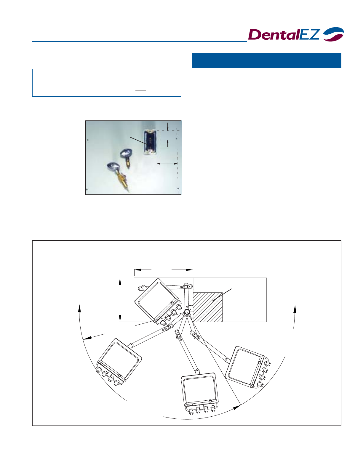
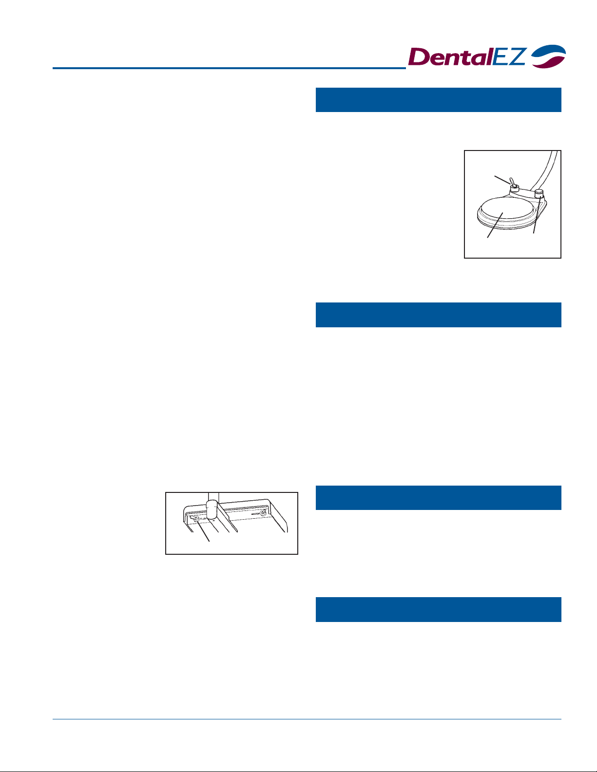
Foot Control
A li ht pressure on the
foot control disk causes a
slow speed.
Full pressure on the disc
causes the handpiece to
operate at full speed.
NOTE: The coolant water
Syringe
Chipblower (Optional)
Fiber Optics (Optional)
The speed of the handpiece is controlled by depress-
in the disk located on the foot control.
spray ON/OFF function is also controlled by using
the toggle valve on the foot control as described above.
The syrin e is desi ned to deliver air or water, or a
mixture of air and water, as required.
To deliver water only, press the button on the
syrin e marked with a water drop symbol.
For air only, press the button on the syrin e with
no markin .
To et a spray mixture of air and water, press
both buttons simultaneously.
NOTE: Air and water flows are factory preset.
This feature is used to blow debris away from the
cuttin site by creatin an air blast throu h the hand-
piece without causin the burr to rotate. To operate
the chip blower, depress and hold down the valve on
the upper ri ht of the foot control.
The fiber optics control is automatically activated by
operatin the handpiece usin the foot control.
NOTE: When the foot control is released, the fiber
optics light will stay on for approximately ten seconds to
allow inspection of the cutting site.
delivery head,
to the left
and hold it
there for 20
seconds.
NOTE: Flushing the water line in the handpiece can
be done by operating the FLUSH toggle valve while
either fully depressing or not depressing the foot control.