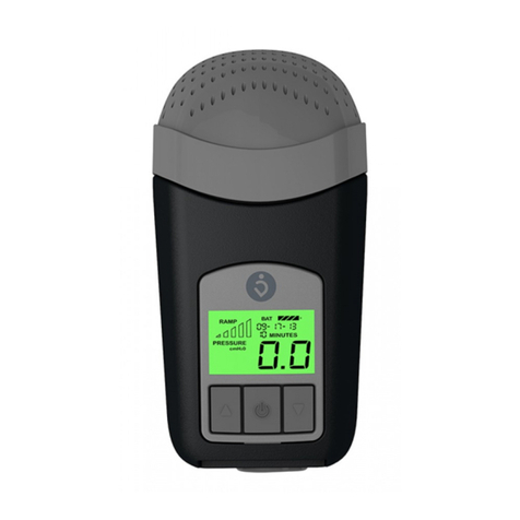
Breas PV 102+ User manual

PV 101+/PV 102+ Service Manual TABLE OF CONTENTS
Doc. No. 003259 En Issue: X-1 BREAS MEDICAL TOC – 1
TABLE OF CONTENTS
1 INTRODUCTION............................................................................. 1–1
1.1 About the PV 101+ and PV 102+............................................................1–1
1.1.1 Intended use of the PV 101+ ................................................................1–1
1.1.2 Intended use of the PV 102+ ................................................................1–1
1.1.3 Design and function ..............................................................................1–1
1.1.4 Service personnel’s training requirements............................................1–1
1.2 About this manual ...................................................................................1–2
1.2.1 Scope....................................................................................................1–2
1.2.2 Intended audience.................................................................................1–2
1.2.3 Icons......................................................................................................1–2
2 MAINTENANCE SERVICE INSTRUCTIONS................................. 2–1
2.1 Purpose of the maintenance ...................................................................2–1
2.2 Introduction .............................................................................................2–2
2.2.1 Service check schedule ........................................................................2–2
2.2.2 Safety precautions ................................................................................2–2
2.2.3 Service record.......................................................................................2–2
2.2.4 Inspection equipment and tools ............................................................2–3
2.2.5 Replacement parts................................................................................2–3
2.3 Preparing inspection................................................................................2–4
2.3.1 Verifying the components and the installed software............................2–4
2.3.2 Initial recording......................................................................................2–4
2.3.3 Markings................................................................................................2–4
2.3.4 Information from the patient/user..........................................................2–4
2.3.5 Validity of the documentation................................................................2–4
2.4 External inspection..................................................................................2–5
2.4.1 Visual inspection for external damage and wear ..................................2–5
2.4.2 Checking the power supply connection.................................................2–5
2.4.3 Short function check..............................................................................2–5
2.5 Internal inspection...................................................................................2–6
2.5.1 Opening the casing...............................................................................2–6
2.5.2 Cleaning the inside of the machine.......................................................2–6
2.5.3 Inspecting the internal wiring.................................................................2–6
2.5.4 Securing the components .....................................................................2–6
2.5.5 Checking the power supply...................................................................2–6
2.5.6 Checking the electrical safety values....................................................2–6
2.5.7 Calibrating the pressure sensor............................................................2–6
2.5.8 Calibrating the flow sensor....................................................................2–6
2.5.9 Calibrating the high pressure limit.........................................................2–6
2.5.10 Reassembling the casing......................................................................2–6

TABLE OF CONTENTS PV 101+/PV 102+ Service Manual
TOC – 2 BREAS MEDICAL Doc. No. 003259 En Issue: X-1
2.6 Final inspection before delivery ..............................................................2–7
2.6.1 Function check...................................................................................... 2–7
2.6.2 Checking the low pressure leakage alarm (PV 102+)........................... 2–7
2.6.3 Checking the trigger function ................................................................ 2–7
2.6.4 Checking the pressure and rate............................................................ 2–7
2.6.5 Replacing the filters...............................................................................2–8
2.6.6 Checking the accessories..................................................................... 2–8
2.6.7 Adjusting the settings for the patient.....................................................2–8
3 REMOVING/REPLACING THE MAIN COMPONENTS ................. 3–1
3.1 Tools.......................................................................................................3–1
3.2 Removing and reassembling the upper casing.......................................3–2
3.3 Removing and replacing the CPU board ................................................3–3
3.4 Removing and reassembling the main assembly ...................................3–4
3.5 Removing and replacing the blower unit.................................................3–6
3.6 Removing and replacing the power board..............................................3–7
3.7 Removing and replacing the MDA board................................................3–8
4 CALIBRATION INSTRUCTIONS.................................................... 4–1
4.1 Requirements..........................................................................................4–1
4.2 Equipment...............................................................................................4–1
4.3 Calibrating the pressure sensor..............................................................4–2
4.4 Verifying the pressure calibration............................................................4–3
4.5 Calibrating the flow sensor......................................................................4–4
4.6 Calibrating the high pressure limit...........................................................4–5
5 PARTS DRAWINGS AND PART-NUMBER LISTS ....................... 5–1
5.1 Overview – Main components.................................................................5–2
5.2 Parts drawings........................................................................................5–4
5.2.1 Parts drawing – Upper and lower casing..............................................5–5
5.2.2 Parts drawing – Main assembly............................................................ 5–6
5.2.3 Parts drawing – Blower unit and patient air outlet................................. 5–7
5.3 Part-number lists.....................................................................................5–8
5.3.1 Part-number list – Upper and lower casing...........................................5–8
5.3.2 Part-number list – Main assembly.........................................................5–9
5.3.3 Part-number list – Blower unit and patient outlet ..................................5–10
5.3.4 Part-number list – Miscellaneous..........................................................5–11
6 FUNCTIONAL DIAGRAMS ............................................................ 6–1
6.1 Pneumatic diagram.................................................................................6–1
6.2 Functional block diagram........................................................................6–2

PV 101+/PV 102+ Service Manual TABLE OF CONTENTS
Doc. No. 003259 En Issue: X-1 BREAS MEDICAL TOC – 3
7 ELECTRONICS............................................................................... 7–1
7.1 Electronics – Main components ..............................................................7–2
7.2 Functional block diagram ........................................................................7–4
7.3 Internal wiring diagram............................................................................7–5
7.4 Circuit board descriptions........................................................................7–6
7.4.1 CPU board ............................................................................................7–6
7.4.2 Power board..........................................................................................7–6
7.4.3 MDA board............................................................................................7–7
7.5 Electrical safety measurements ..............................................................7–8
7.6 Circuit diagrams – Circuit boards............................................................7–9
7.6.1 Circuit diagram – CPU board 1, rev 2...................................................7–10
7.6.2 Circuit diagram – CPU board 2, rev 2...................................................7–11
7.6.3 Circuit diagram – CPU board 3, rev 2...................................................7–12
7.6.4 Circuit diagram – CPU board 4, rev 2...................................................7–13
7.6.5 Circuit diagram – CPU board 5, rev 2...................................................7–14
7.6.6 Circuit diagram – Power board 1, rev 3.................................................7–15
7.6.7 Circuit diagram – Power board 2, rev 3.................................................7–16
7.6.8 Circuit diagram – MDA board 1, rev 3...................................................7–17
7.6.9 Circuit diagram – MDA board 2, rev 3...................................................7–18
7.6.10 Circuit diagram – MDA board 3, rev 3...................................................7–19
7.7 Component location drawings – Circuit boards.......................................7–20
7.7.1 Component location drawing – CPU board...........................................7–21
7.7.2 Component location drawing – Power board, upper side .....................7–22
7.7.3 Component location drawing – Power board, under side .....................7–23
7.7.4 Component location drawing – MDA board ..........................................7–24
7.8 Component lists – Circuit boards ............................................................7–25
7.8.1 Component list – CPU board ................................................................7–25
7.8.2 Component list – Power board..............................................................7–26
7.8.3 Component list – MDA board................................................................7–29
8 FAULT TRACING........................................................................... 8–1
8.1 Fault-tracing table....................................................................................8–1
9 APPENDICES................................................................................. 9–1
9.1 Engineering change history – PV 101+...................................................9–1
9.2 Engineering change history – PV 102+...................................................9–1
Service Record for BREAS PV 101+/PV 102+
9.3 Returning products to BREAS.................................................................9–5
Service Report for BREAS PV 101+/PV 102+

PV 101+/PV 102+ Service Manual INTRODUCTION
Doc. No. 003259 En Issue: X-1 BREAS MEDICAL 1–1
1 INTRODUCTION
This chapter gives an overview of the PV 101+ and PV 102+ devices and the service
manual.
1.1 About the PV 101+ and PV 102+
The PV 101+ and PV 102+ are intended for use in homes, while travelling or in institu-
tions. They are bi-level devices, which means that the expiration pressure (EPAP) can
be set lower than the inspiration pressure (IPAP).
1.1.1 Intended use of the PV 101+
The BREAS PV 101+ device is intended for treatment of obstructive sleep apnoea.
1.1.2 Intended use of the PV 102+
The BREAS PV 102+ device is intended for treatment of obstructive and central sleep
apnoea, hypopnea and other forms of sleep-related breathing problems. The back-up
rate is adjustable, as well as the rise time, which makes it possible to customise the time
for the pressure to change from EPAP to IPAP.
1.1.3 Design and function
The PV 101+ and PV 102+ are based on a blower which is driven by an electronically
controlled servomotor. The microprocessor-based electronics calculates, from the set
pressure, rate, rise time etc., the correct motor speed. The set pressure and trigger sen-
sitivity is continuously monitored.
An audible alarm is immediately given in the event of a power failure.
1.1.4 Service personnel’s training requirements
Service personnel working with the PV 101+ and PV 102+ devices should have medi-
cal/technical training and a good knowledge of the construction and function of respira-
tory devices. Authorisation by BREAS PV 101+/PV 102+ service training is
recommended.
Always contact your BREAS representative if you have any questions or if
training is required.
WARNING!
This product must be:
• subjected to regular service, maintenance and control and any applicable upgrades,
in accordance with BREAS service instructions;
• repaired and/or modified in accordance with BREAS service manuals, technical bul-
letins and any special service instructions, by service technicians that have been
authorised after BREAS PV 101+/PV 102+ service training, or have an equivalent
technical knowledge on medical respiratory devices.
Deviation from these service instructions may lead to risk of personal injury!

INTRODUCTION PV 101+/PV 102+ Service Manual
1–2 BREAS MEDICAL Doc. No. 003259 En Issue: X-1
1.2 About this manual
1.2.1 Scope
All the maintenance checkpoints and the additional service actions for the PV 101+/
PV 102+ are described in this manual. It contains all documentation required for main-
taining and servicing the machines, such as enlarged drawings, wiring diagrams, com-
ponent location guides and so on.
BREAS Medical reserves the right to make changes to the products and/or the contents
of this manual without any prior notice.
1.2.2 Intended audience
This service manual is intended for service technicians who have medical/technical
training and who have a good knowledge of the construction and function of respiratory
devices.
The service manual is NOT intended for clinic personnel or patients, who can find
all the information they need in the PV 101+ and PV 102+ Operating Manuals.
1.2.3 Icons
Icons are used in this manual to highlight specific types of information. The meaning of
each icon is explained in the table below.
Icon Explanation
Warning!
Risk of death and serious personal injury.
Caution!
• Risk of minor or moderate injury.
• Risk of equipment damage, loss of data, extra work or unexpected results.
Note
Information that may be valuable but is not of critical importance, tips.
Reference
Reference to other manuals with additional information on a specific topic.

Doc. No. 003259 En Issue: X-1 BREAS MEDICAL 2–1
PV 101+/PV 102+ Service Manual MAINTENANCE SERVICE INSTRUCTIONS
2 MAINTENANCE SERVICE INSTRUCTIONS
This chapter describes all the routine checks and additional service instructions for the
PV 101+ and PV 102+.
For information about fault tracing, parts drawings, board schematics and so on, refer to
the respective chapter in this service manual.
The patient and/or care provider should follow the function checks described in the
chapter “CHECKS BEFORE USE” in the PV 101+/PV 102+ Operating Manual.
2.1 Purpose of the maintenance
The PV 101+ and PV 102+ are designed to give the users many years of trouble-free
assistance, provided that preventive maintenance is carriedout at the intervals specified
in this manual. Well-performed maintenance will considerably increase the life of the
machine.
It is also important to check any peripheral equipment at the same time as services are
carried out.
WARNING!
This product must be:
• subjected to regular service, maintenance and control and any applicable upgrades,
in accordance with BREAS service instructions;
• repaired and/or modified in accordance with BREAS service manuals, technical bul-
letins and any special service instructions, by service technicians that have been
authorised after BREAS PV 101+/PV 102+ service training, or have an equivalent
technical knowledge on medical respiratory devices.
Deviation from these service instructions may lead to risk of personal injury!

MAINTENANCE SERVICE INSTRUCTIONS PV 101+/PV 102+ Service Manual
2–2 BREAS MEDICAL Doc. No. 003259 En Issue: X-1
2.2 Introduction
Before you start the maintenance service, read the safety precautions and make sure
you have a new service record and all the necessary equipment, tools and replacement
parts at hand.
2.2.1 Service check schedule
The schedule below lists the recurrent service checks of the PV 101+/PV 102+’s com-
ponents and the intervals at which they should be performed. The reference numbers
refer to chapters and sections in this manual that contain more detailed instructions.
A complete maintenance service, as described in this chapter, must be car-
ried out at least every 12 months.
2.2.2 Safety precautions
Follow the safety precautions below when working with the PV 101+/PV 102+:
• Do not work on the device with the casing removed and any power supply con-
nected unless the instructions in this manual clearly say so.
• Always use caution when working with the device connected to the mains and the
casing removed.
• Make sure that all precautions to prevent electrostatic discharge (ESD) have been
taken. Follow all the regulations regarding ESD.
• Explosive gases and liquids must not be kept or used near the PV 101+/PV 102+.
The PV 101+/PV 102+ Operating Manual contains an extended list of safety pre-
cautions.
2.2.3 Service record
See section 9, “APPENDICES” for the BREAS service record.
• Copy the service record and use it for noting the service checks while performing
the yearly service.
Interval Service check See
section
Every 12 months Complete maintenance check 2
Check the electrical safety limit values. 7.5
Calibrate the pressure, flow and high pressure limit
sensors. 4
Every 15,000 operating
hours or when required Replace the blower unit. 3.5
Calibrate the pressure, flow and high pressure limit
sensors. 4

Doc. No. 003259 En Issue: X-1 BREAS MEDICAL 2–3
PV 101+/PV 102+ Service Manual MAINTENANCE SERVICE INSTRUCTIONS
2.2.4 Inspection equipment and tools
Before servicing the PV 101+/PV 102+, make sure you have the following equipment at
hand:
• Test lung
• Multimeter
• Measuring equipment for pressure 0–70 mbar
(Thommen HM 28 digital manometer is recommended, BREAS part no. 001934)
•Flowmeter
• Screwdrivers TX10, TX25, Phillips 1
• Box socket wrenches M3, M4
• Allen key 2, 5x25
For the equipment required when calibrating the device, see section 4.2.
2.2.5 Replacement parts
The following parts should be available when servicing the device:
Description BREAS part no.
Patient tube 000245
Patient air filter, washable (2 pcs) 000996
Patient air filter, disposable (if used) 001259
Air filter, internal cooling 001121
Blower unit assembly, 15.000 hours 003110

MAINTENANCE SERVICE INSTRUCTIONS PV 101+/PV 102+ Service Manual

2–4 BREAS MEDICAL Doc. No. 003259 En Issue: X-1
2.3 Preparing inspection
2.3.1 Verifying the components and the installed software
• Check section 9.1, “Engineering change history – PV 101+” or section 9.2, “Engi-
neering change history – PV 102+” to find out what changes have been made to
the device and from which serial number they were implemented.
If in any doubt about the circuit board revisions or upgrades that may have been made
that have not been recorded, check the component designations on the circuit boards.
2.3.2 Initial recording
1Copy a new service record (see section 9, “APPENDICES”).
2Identify the PV 101+/PV 102+; note the model and serial number and any inven-
tory number, if applicable, on the service record.
3Check earlier actions and events recorded on any previous service records.
4Note the current patient settings.
5Note the total number of operating hours.
2.3.3 Markings
Check that the following markings are legible:
• Make, model designation, serial number
• Warning texts
• Any inventory markings
• Any other texts on the external equipment and accessories
2.3.4 Information from the patient/user
Before starting the service, check the following with the patient/clinic:
• Has the PV 101+/PV 102+ functioned without any problems? If not, what were
they?
• How does the patient/care provider check the function of the device? How often?
• How often are the filters changed?
• How many filters will be required before the next service?
• Other observations?
2.3.5 Validity of the documentation
1Check that the documentation used by the patient is valid and up to date.
2Check if any modification or revision of the PV 101+/PV 102+ needs to be done at
the same time as the service.

Doc. No. 003259 En Issue: X-1 BREAS MEDICAL 2–5
PV 101+/PV 102+ Service Manual MAINTENANCE SERVICE INSTRUCTIONS
2.4 External inspection
2.4.1 Visual inspection for external damage and wear
1Clean the cover of the PV 101+/PV 102+ using a mild detergent.
2Check for visible damage to the cover and other components.
3Check that all external parts are tightened and secured.
2.4.2 Checking the power supply connection
1Check the plug, power cord and mains power socket.
2Make sure the strain-relief clamp for the power cord is not damaged.
3Check the power supply to the machine.
4If the PV 101+ does not operate from the mains power, check the fuses.
2.4.3 Short function check
1Connect the power cord to the power socket of the PV 101+/PV 102+.
2Connect the patient circuit.
3Start the PV 101+/PV 102+ and check that it functions normally.
4Disconnect the power cord and check that the power failure alarm sounds. Recon-
nect the power cord. The alarm should be silenced.
5Switch on the PV 101+/PV 102+. Upon starting, all the LEDs on the front panel
should be lit and the trigger settings should be indicated on the bar graph. The
entire bar graph should then become yellow for 2 seconds before the device starts
functioning normally.
6(PV 102+ only) Switch on the PV 102+ and wait for 15 seconds for the leakage
alarm to be activated.
7Switch off the device.

MAINTENANCE SERVICE INSTRUCTIONS PV 101+/PV 102+ Service Manual
2–6 BREAS MEDICAL Doc. No. 003259 En Issue: X-1
2.5 Internal inspection
Disconnect the power supply before removing the casing of the machine.
2.5.1 Opening the casing
• For instructions, see section 3.2, “Removing and reassembling the upper casing”.
2.5.2 Cleaning the inside of the machine
• Remove any dust or dirt that has collected in the machine.
2.5.3 Inspecting the internal wiring
• Inspect all wiring and the connectors for damage. Make sure that no wires or
cables are pinched.
2.5.4 Securing the components
• Make sure that all the internal components, such as the motor unit, the circuit
boards, the connectors and so on, are properly secured.
2.5.5 Checking the power supply
1Check that the power inlet socket is undamaged and that it is properly fastened.
2Make sure the power board is properly fastened.
3Check the wiring to and from the power board.
2.5.6 Checking the electrical safety values
• For instructions, see section 7.5, “Electrical safety measurements”.
2.5.7 Calibrating the pressure sensor
• For instructions, see section 4.3, “Calibrating the pressure sensor”.
2.5.8 Calibrating the flow sensor
• For instructions, see section 4.5, “Calibrating the flow sensor”.
2.5.9 Calibrating the high pressure limit
• For instructions, see section 4.6, “Calibrating the high pressure limit”.
2.5.10 Reassembling the casing
• For instructions, see section 3.2, “Removing and reassembling the upper casing”.

Doc. No. 003259 En Issue: X-1 BREAS MEDICAL 2–7
PV 101+/PV 102+ Service Manual MAINTENANCE SERVICE INSTRUCTIONS
2.6 Final inspection before delivery
2.6.1 Function check
1Connect the power cord to the power socket of the PV 101+/PV 102+.
2Connect the patient circuit.
3Start the PV 101+/PV 102+ and check that it functions normally.
4Disconnect the power cord and check that the power failure alarm sounds. Recon-
nect the power cord. The alarm should be silenced.
5Switch on the PV 101+/PV 102+. Upon starting, all the LEDs on the front panel
should be lit and the trigger settings should be indicated on the bar graph. The
entire bar graph should then become yellow for 2 seconds before the device starts
functioning normally.
6(PV 102+ only) Switch on the PV 102+ and wait for 15 seconds for the leakage
alarm to be activated.
7Switch off the device.
2.6.2 Checking the low pressure leakage alarm (PV 102+)
1Adjust the pressure settings to:
IPAP 10 mbar
EPAP 10 mbar
2Make sure that the alarm LED is lit and that an audible alarm is heard.
2.6.3 Checking the trigger function
1Adjust the pressure settings to:
IPAP 10 mbar
EPAP 4 mbar
2Connect the patient tube without a mask.
3Block the air outlet on the tube. When you remove the blockage, a triggered
breath should be initiated.
2.6.4 Checking the pressure and rate
Pressure
The measurement should be made using a blocked patient circuit with leakage provided
(see figure below).
1Adjust the pressure settings to:
IPAP 10 mbar
EPAP 10 mbar
2Measure the pressure and check that it is correct (tolerance: ±4% of the maximum
value and ±8% of the current pressure value).

MAINTENANCE SERVICE INSTRUCTIONS PV 101+/PV 102+ Service Manual
2–8 BREAS MEDICAL Doc. No. 003259 En Issue: X-1
Rate
3Adjust the settings to:
IPAP 10 mbar
EPAP 4 mbar
Back-up rate 8 BPM (PV 102+ only)
The PV 101+ back-up rate is fixed to 6 BPM.
4Measure the rate and check that it is correct.
2.6.5 Replacing the filters
The patient air filters are located in the filter holder under the carrying handle of the
device. The internal cooling filter is located in the lower casing.
1Replace the washable grey air filter.
2Replace the disposable white filter, if used.
3Replace the internal cooling filter from underneath the machine.
2.6.6 Checking the accessories
1Inspect the patient circuit. Replace it if necessary.
2Inspect any other accessories.
2.6.7 Adjusting the settings for the patient
• Adjust all the patient settings to the prescribed values.
mbar
Pressure gauge
5 mm leakage
Patient circuit Plug

PV 101+/PV 102+ Service Manual REMOVING/REPLACING THE MAIN COMPONENTS
Doc. No. 003259 En Issue: X-1 BREAS MEDICAL 3–1
3 REMOVING/REPLACING THE MAIN COMPONENTS
This chapter describes how to install, remove and/or replace the main components of
the PV 101+/PV 102+.
3.1 Tools
Before disassembling the PV 101+/PV 102+, make sure you have the following tools at
hand:
• Screwdriver TX10
• Screwdriver TX25
• Screwdriver Phillips 1
• Box socket wrench M4
• Box socket wrench M3

REMOVING/REPLACING THE MAIN COMPONENTS PV 101+/PV 102+ Service Manual
3–2 BREAS MEDICAL Doc.No.003259En Issue: X-1
3.2 Removing and reassembling the upper casing
Disconnect the power supply before removing the casing of the machine.
To remove the casing:
1Remove the mains power cord.
2Turn the PV 101+/PV 102+ upside down. Remove the four screws placed in the
four holes underneath the lower casing and the two screws placed underneath the
handle.
3Lift up the upper casing. Disconnect the CPU board’s ribbon cable from the MDA
board. Put the upper casing aside.
To reassemble the casing:
• Reassemble in reverse order.
6 ×TX25

PV 101+/PV 102+ Service Manual REMOVING/REPLACING THE MAIN COMPONENTS
Doc. No. 003259 En Issue: X-1 BREAS MEDICAL 3–3
3.3 Removing and replacing the CPU board
To remove the CPU board:
1Remove the upper casing (See section 3.2).
2Turn it upside down and remove the three Torx screws placed underneath the
CPU board.
3Remove the CPU board.
To reassemble the CPU board:
• Reassemble in reverse order. Fit the components to the holes for the display
panel controls and screw the CPU board back in place.
3 ×TX10

REMOVING/REPLACING THE MAIN COMPONENTS PV 101+/PV 102+ Service Manual
3–4 BREAS MEDICAL Doc.No.003259En Issue: X-1
3.4 Removing and reassembling the main assembly
All the main internal components – blower unit, power board and MDA board – are
mounted on the base plate.
To remove the main assembly:
1Remove the upper casing (See section 3.2).
2Turn the PV 101+/PV 102+ upside down. Remove the M4 nut that fastens the
blower unit rubber mount.
3Remove the five screws on the lower casing that hold the base plate.
5 ×TX10
3
2
1 ×M4
Compound
nut

PV 101+/PV 102+ Service Manual REMOVING/REPLACING THE MAIN COMPONENTS
Doc. No. 003259 En Issue: X-1 BREAS MEDICAL 3–5
4Press the rear panel side of the lower casing outwards to release the connectors
and lift out the main assembly.
To reassemble the main assembly:
• Reassemble in reverse order. Make sure the connectors on the rear panel are
properly fitted in their holes.

REMOVING/REPLACING THE MAIN COMPONENTS PV 101+/PV 102+ Service Manual
3–6 BREAS MEDICAL Doc.No.003259En Issue: X-1
3.5 Removing and replacing the blower unit
To remove the blower unit:
1Remove the upper casing (See section 3.2).
2Remove the main assembly (See section 3.4).
3Disconnect the motor connectors from the MDA board.
4Disconnect the flex tube from the blower unit’s air outlet. Disconnect the red sen-
sor tube from the blower unit’s sensor connector.
5Remove the remaining two nuts that hold the blower unit’s rubber mounts from
underneath the base plate.
6Lift away the complete blower unit.
To reassemble the blower unit:
• Reassemble in reverse order.
2 ×M4 Compound nut
3
3
5
4
5
This manual suits for next models
1
Table of contents
Other Breas Medical Equipment manuals

Breas
Breas Vivo 65 User manual

Breas
Breas NIPPY Clearway User manual

Breas
Breas iSleep 20+ User manual

Breas
Breas Vivo 50 User manual

Breas
Breas Z1 User manual

Breas
Breas Vivo 45 LS User manual

Breas
Breas iSleep20+ User manual

Breas
Breas Vivo 1 User manual

Breas
Breas Clearway 2 User manual

Breas
Breas Z2 Auto User manual

Breas
Breas Vivo 50 User manual

Breas
Breas Vivo 3 User manual

Breas
Breas Clearway 2 User manual

Breas
Breas NIPPY Clearway User manual

Breas
Breas Vivo 40 User manual

Breas
Breas Nippy 4 Series User manual

Breas
Breas Vivo 45 LS User manual

Breas
Breas Vivo 40 User manual

Breas
Breas Vivo30 User manual

Breas
Breas NIPPY User manual