manuals.online logo
Brands
  1. Home
  2. •
  3. Brands
  4. •
  5. Desa
  6. •
  7. Fireplace Accessories
  8. •
  9. Desa GA3700T User manual

Desa GA3700T User manual

Parts included with this kit:
Part No. Description Quantity
Instruction Sheet 1
103581-01 Blower 1
101614-02 Switch and Cover Assembly 1
101398-02 Wire Harness 1
104036-01 Power Cord and Plate Assembly 1
104038-01 Mounting Hardware Kit 1
(includes all parts below)
M11084-26 #10 x 3/8" sheet metal screws 1
M11084-38 #8 x 3/8" sheet metal screws 3
103708-01 #6 x 1/4" sheet metal screws 2
099123-01 Wire Clips 3
099998-01 Fan Switch 1
101584-04 Wiring Diagram Decal 1
101629-01 Plastic Hole Bushing 1
Tools Required
• Flat Blade Screwdriver
• Phillips Screwdriver
If any of these pieces are missing or damaged, contact the dealer where you purchased this
kit or DESA International at 1-800-972-7879 for referral information.
INSTALLATION INSTRUCTIONS
FOR GA3700T/GA3650T/FA3700T
BLOWER ACCESSORY
DESA INTERNATIONAL
(Check your owners manual for specific applications and additional instructions.)
WARNING: ELECTRICAL GROUNDING INSTRUCTIONS
This appliance is equipped with a three-prong (grounding) plug
foryourprotectionagainstshockhazardandshouldbeplugged
directly into a properly grounded three-prong receptacle.
2
104004
DESA INTERNATIONAL
GA3650T/GA3700T/FA3700T BLOWER ACCESSORIES
AUTO
OFF
ON
3
2
1
1. Remove fireplace screen per the in-
structionsin operation manualsupplied
with fireplace.
2. If logs are installed, carefully remove
the logs and set aside, noting the prop-
erly mounted location of each.
3. Remove screws that attach log base as-
sembly to fireplace (do not discard).
Carefully lift up log base assembly and
remove from fireplace, taking care to
pull flexible gas line through the ac-
cess holes (see Figure 1).
4. Place the blower againstlowerrear wall
of firebox outer wrapper with the ex-
haust port directed upward. Align the
holes in top mounting tabs of blower
with holes in wall of wrapper (see Fig-
ure 2). Using two #8 screws provided,
mount blower and tighten screws
firmly.
5. Route terminals end of power cord
through large hole near top of left floor
support bracket. Make sure to pass the
cordfromthe outside (left side) towards
the center of firebox (see Figure 3).
6. Using two #6 screws provided attach
power cord mounting plate to the out-
side face of left floor support bracket.
Drive screws from inside (right side)
of floor support bracket. Attach the
plate so that the power cord is directed
towards rear of firebox (see Figure 3).
Tighten screws firmly.
7. Remove the three screws (do not dis-
card) and cover plate from center of
firebox wrapper rear wall. Discard this
cover plate (see Figure 4).
Figure 1 - Removing Log Base from Fire-
place
Figure 2 - Mounting Blower to Firebox
Figure 3 - Installing Power Cord, Mount-
ing Plate, and Selector switch
8. Mount the supplied thermostaticswitch
and cover assembly into firebox wrap-
per wall. Do this by feeding terminal
ends of wire harness into the hole. Al-
low wires to fall to bottom of firebox
cavity (see Figure 4).
9. Using three screws from step 7, attach
switch and cover assembly to firebox
wrapper rear wall. Tighten screws
firmly (see Figure 4).
10. Mount selector switch to front flange
of left floor support bracket. Align
graphics on switch upright and push
firmly to snap switch into rectangular
hole. Push the selector switch to the off
(middle) position (see Figure 3).
11. Install three plastic wire clips provided
into floor support bracket (see Figure
3). Secure by pushing clips firmly into
holes.
Figure 4 - Installing Switch and Cover
Assembly
NOTICE:Shut-offgassupplyand
disconnect heater from gas sup-
ply. Contact a qualified service
person to do this.
CAUTION: Do not pick up log
base assembly by burners. This
could damage burners. Only
handle base by grates.
Screws
Log Base Flexible Gas Line
Blower
#8 Screws
Lower
Rear Wall
of Firebox #6 Screws #10 Screw
Wire
Clips
Selector
Switch
Switch and
Cover Assembly
Exhaust
Port
Top
Mounting
Tab
Note:
Appearance of fireplace may vary
by model.
INSTALLING
GA3650T/GA3700T/
FA3700T BLOWER
ACCESSORY IN A
32" FIREBOX
3
104004
INSTALLATION INSTRUCTIONS
14. Secure wires into the appropriate plas-
tic wire clips (see Figure 6).
15. Plug in blower power cord.
a.If yourfireplace systemis installed
as a freestanding unit with an ac-
cessory mantel, install one plastic
bushing (provided) into the 1.5" hole
in the lower left side of the outer cas-
ing (see Figure 7). Route power cord
through plastic bushing. Plug the
power cord into a properly grounded
three-prong wall receptacle near the
firebox.
b.If your fireplacesysteminstallation
is recessed, install one plastic bush-
ing provided into the 1.5" hole near
the middle of the left floor support
bracket (see Figure 7). Route power
cordthroughplasticbushing.Plugthe
power cord into a properly installed
duplex outlet. (If an outlet is not in-
stalledinyour fireplace, the accessory
modelGA3555 Outlet Kitwith cover
canbeinstalledinyourfireplace.This
will supply a convenient three-prong
grounded electrical outlet for your
blower. Refer to the installation
manual provided with the model
GA3555accessoryforinstructionson
wiring the duplex outlet.)
Note:
Aqualifiedinstaller must make
all electrical connections.
16. Check to make sure that the power cord
and wires are completely clear of the
blowerwheeland that there are noother
foreign objects in blower wheel. Turn
bloweron by pushing the selectorswitch
to the on position and check for opera-
tion. Turn blower off before continuing.
Figure 6 - Wire Attachment
Figure 5 - Installing Switch and Cover
Assembly
Figure 7 - Installing Bushings
Bushing Location
for Recessed
Installation
Bushing Location for
Freestanding Installation
Note:
To prevent short circuit, white wire
MUST be connected to motor.
12. Attach green ground wire ring termi-
nal to floor support bracket using #10
sheet metal grounding screw provided
(see Figure 3, page 2). Tighten screw
firmly.
13. Attach all five remaining wiring termi-
nals to the appropriate switch or motor
terminal. Carefully note the correct
color coding (see Figures 6 and 8, page
4). Push female wire terminals fully
onto male terminal.
Plastic Bushing
WARNING:Failuretoconnect
all wires properly as indicated
maycauseelectricalshortcircuit
or personal injury. A qualified
electrician should check that all
connections are made properly.
Switch and
Cover Assembly
AUTO
OFF
ON
3
2
1
Blue Wire
Red Wire
Green Wire
Black Wire
White Wire
Blue Wire
To Switch and
Cover Assembly
WARNING: Never touch the
blower wheel while in operation.
INSTALLING
GA3650T/GA3700T/
FA3700T BLOWER
ACCESSORY IN A
32" FIREBOX
Continued
Continued
4
104004
DESA INTERNATIONAL
GA3650T/GA3700T/FA3700T BLOWER ACCESSORIES
WARNING: A qualified ser-
vice person must connect fire-
place to gas supply. Follow all
local codes.
104004-01
REV. F
07/99
17. Peel off the backing paper and stick the
supplied wiring diagram decal on the
firebox bottom approximately 12" in
front of blower.
18. Replacelog base assemblyin fireplace.
Feed flexible gas supply line into fire-
placebasearea while replacing log base
assembly. Make sure the entire flexible
gas line is in fireplace base area.
Note:
Iffirebrickis installed,makesure
the back of the firebox bottom slides
undertherear panel of the firebrick.(lift
the firebrick up if necessary.)
IMPORTANT:
Do not pick up log base
assembly by burners. This could damage
burners. Only handle base by grates.
19. Reattach log base assemblytofireplace
with screws removed in step 3.
20. Install logs and fireplace screen per in-
structions in operating manual provided
with fireplace.
LIMITED WARRANTY
DESAInternationalwarrants this producttobefreefromdefectsinmaterialsandworkmanshipforone(1)yearfrom the dateoffirstpurchase,
provided that the product has been properly operated.
This warranty is extended only to the original purchaser. DESA shall either replace the product or refund the full purchase price. Warranty
service is available only through authorized dealers.
This warranty does not apply to the failure of any part resulting from accident or misuse by the owner, nor does it apply to use in commercial
applications.
To the full extent allowed by the law of the jurisdiction that governs the sale of the product: this express warranty excludes any and all other
expressed warranties. The above expressed warranty is in lieu of all other warranties either expressed or implied including but not limited to
the implied warranties of merchantability and fitness for a particular purpose. DESA’s liability is hereby limited to the purchase price of the
product, and DESA shall not be liable for any other damages whatsoever including indirect, incidental, or consequential damages.
Some states do not allow a limitation on how long an implied warranty lasts, or an exclusion or limitation of incidental or consequential
damages, so the above limitation or implied warranties, or exclusion or limitation on damages may not apply to you.
This warranty gives you specific legal rights, and you may also have other rights which vary from state to state.
For information about this warranty write:
2701 Industrial Drive
P.O. Box 90004
Bowling Green, KY 42102-9004
www.desatech.com
INTERNATIONAL
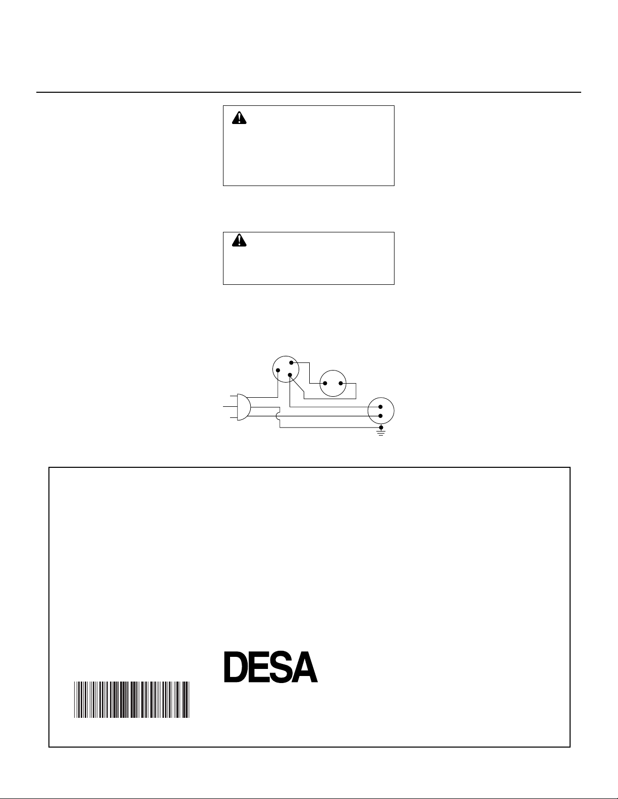
Figure 8 - Wiring Diagram
If any of the original wire as supplied with
the appliance must be replaced, it must be
replaced with 105˚C wire or it's equivalent.
21. Connect gas supply to fireplace per in-
structionsinoperating manual provided
with fireplace.
WARNING:Failuretoposition
the parts in accordance with sup-
plied diagrams or failure to use
only parts specifically approved
withthisheatermayresultindam-
age or personal injury.
OPERATING THE BLOWER
Light your gas appliance with the blower
off. After about 5 minutes, turn the blower
on to deliver heated air at the top louvers.
Thethermostatically-controlledblowerfea-
tures a three position switch. The three set-
tings are: ON, OFF, and AUTO. In the ON
position,theblowerwilloperateconstantly.
In the OFF position, the blower will not
operate. In the AUTO position, the blower
will start when the thermostat senses a suf-
ficient increase in firebox temperature.
Note:
Your gas logs and thermostat blower
willnotturnonandoffatthesametime.The
fireplacemayrunforseveralminutesbefore
the blower turns on. After the heater modu-
lates to the pilot position, the blower will
continue to run. The blower will shut off
after the firebox temperature decreases.
Note:
It is safe to operate fireplace with
blower turned off. However, the blower
helps distribute heated air from the fire-
place.
Note:
Periodically check the louvers of the
firebox and remove any dust, dirt, or other
obstructions.
NOT A UPC
104004 01
Blue
Fan Switch
(Off/On/Auto)
Red Fan
Switch
(N.O.)
Green
White
On
110/115
V.A.C.
Blower
Motor
Black
Off
1
23
Auto
INSTALLING
GA3650T/GA3700T/
FA3700T BLOWER
ACCESSORY IN A
32" FIREBOX
Continued

This manual suits for next models

2

Other Desa Fireplace Accessories manuals

Desa PCBM-325 User manual

Desa

Desa PCBM-325 User manual

Desa Mantel and Base W26RO Instruction manual

Desa

Desa Mantel and Base W26RO Instruction manual

Desa PC-BVBN User manual

Desa

Desa PC-BVBN User manual

Desa HFL300 SERIES User manual

Desa

Desa HFL300 SERIES User manual

Desa C36TO Instruction manual

Desa

Desa C36TO Instruction manual

Desa HFL200 SERIES User manual

Desa

Desa HFL200 SERIES User manual

Desa W23FT Instruction manual

Desa

Desa W23FT Instruction manual

Desa W32TO Instruction manual

Desa

Desa W32TO Instruction manual

Desa DS37 User manual

Desa

Desa DS37 User manual

Desa Wall Mantel and Base W26LT Instruction manual

Desa

Desa Wall Mantel and Base W26LT Instruction manual

Desa Wall Mantel and Base with Trim W32KCSA Instruction manual

Desa

Desa Wall Mantel and Base with Trim W32KCSA Instruction manual

Desa W32AOSA Instruction manual

Desa

Desa W32AOSA Instruction manual

Desa C26TO Instruction manual

Desa

Desa C26TO Instruction manual

Desa BK3 User manual

Desa

Desa BK3 User manual

Desa Wall Mantel and Base W32LT Instruction manual

Desa

Desa Wall Mantel and Base W32LT Instruction manual

Desa BDMO48E User manual

Desa

Desa BDMO48E User manual

Desa GA6050 User manual

Desa

Desa GA6050 User manual

Desa GB38 User manual

Desa

Desa GB38 User manual

Desa Wall Mantel and Base W26ME Instruction manual

Desa

Desa Wall Mantel and Base W26ME Instruction manual

Desa W23OT Instruction manual

Desa

Desa W23OT Instruction manual

Desa Wall Mantel with Base and Trim WD26CP Instruction manual

Desa

Desa Wall Mantel with Base and Trim WD26CP Instruction manual

Desa GA6050 User manual

Desa

Desa GA6050 User manual

Desa GA9150A User manual

Desa

Desa GA9150A User manual

Desa W32CO Instruction manual

Desa

Desa W32CO Instruction manual

Popular Fireplace Accessories manuals by other brands

Valor G3.5 Series installation manual

Valor

Valor G3.5 Series installation manual

Napoleon EFCN installation instructions

Napoleon

Napoleon EFCN installation instructions

Exodraft Xzense manual

Exodraft

Exodraft Xzense manual

Majestic QUARTZPLA36IN installation instructions

Majestic

Majestic QUARTZPLA36IN installation instructions

Superior MFS Series Operation and service manual

Superior

Superior MFS Series Operation and service manual

Valor LINEAR SERIES installation manual

Valor

Valor LINEAR SERIES installation manual

Firegear FG-H-2110SS Installation and operating instructions

Firegear

Firegear FG-H-2110SS Installation and operating instructions

Travis Industries 864 TRV 31K Framing Guide

Travis Industries

Travis Industries 864 TRV 31K Framing Guide

GHP Group Pleasant Hearth FN-5701 owner's manual

GHP Group

GHP Group Pleasant Hearth FN-5701 owner's manual

IHP PCBE-36 Operation manual

IHP

IHP PCBE-36 Operation manual

Heatmaster CAROLINA HICKORY manual

Heatmaster

Heatmaster CAROLINA HICKORY manual

Gimeg Cosi square glass set M installation instructions

Gimeg

Gimeg Cosi square glass set M installation instructions

BuckMaster EMBER VISION 100 SERIES manual

BuckMaster

BuckMaster EMBER VISION 100 SERIES manual

Fireplace 564 Wilmington Face Installation

Fireplace

Fireplace 564 Wilmington Face Installation

Superior EDGE TRIM KITS installation instructions

Superior

Superior EDGE TRIM KITS installation instructions

Rasmussen LC-18-N Assembly, installation and operation instructions

Rasmussen

Rasmussen LC-18-N Assembly, installation and operation instructions

IHP HeatFlo Kit HTFLO-LIN60 installation instructions

IHP

IHP HeatFlo Kit HTFLO-LIN60 installation instructions

Duluth Forge FVFLC18-1 installation instructions

Duluth Forge

Duluth Forge FVFLC18-1 installation instructions

manuals.online logo
manuals.online logoBrands
  • About & Mission
  • Contact us
  • Privacy Policy
  • Terms and Conditions

Copyright 2025 Manuals.Online. All Rights Reserved.