Desoutter MULTI Quick start guide

Printed Matter No. 6159929540_EN
Issue No. 03
Date 03/2023
MULTI - Modular Spindle Solution
Installation and Upgrade Manual
WARNING
Read all safety warnings and instructions
Failure to follow the safety warnings and instructions may result in
electric shock, fire and/or serious injury.
Save all warnings and instructions for future reference
www.desouttertools.com

6159929540 / v.03 2 / 64 03/2023
Table of Contents
Introduction............................................................................................................................................4
About Installation and Upgrade manual ..........................................................................................4
Warranty..........................................................................................................................................4
Quick Start .............................................................................................................................................5
Read before installing......................................................................................................................5
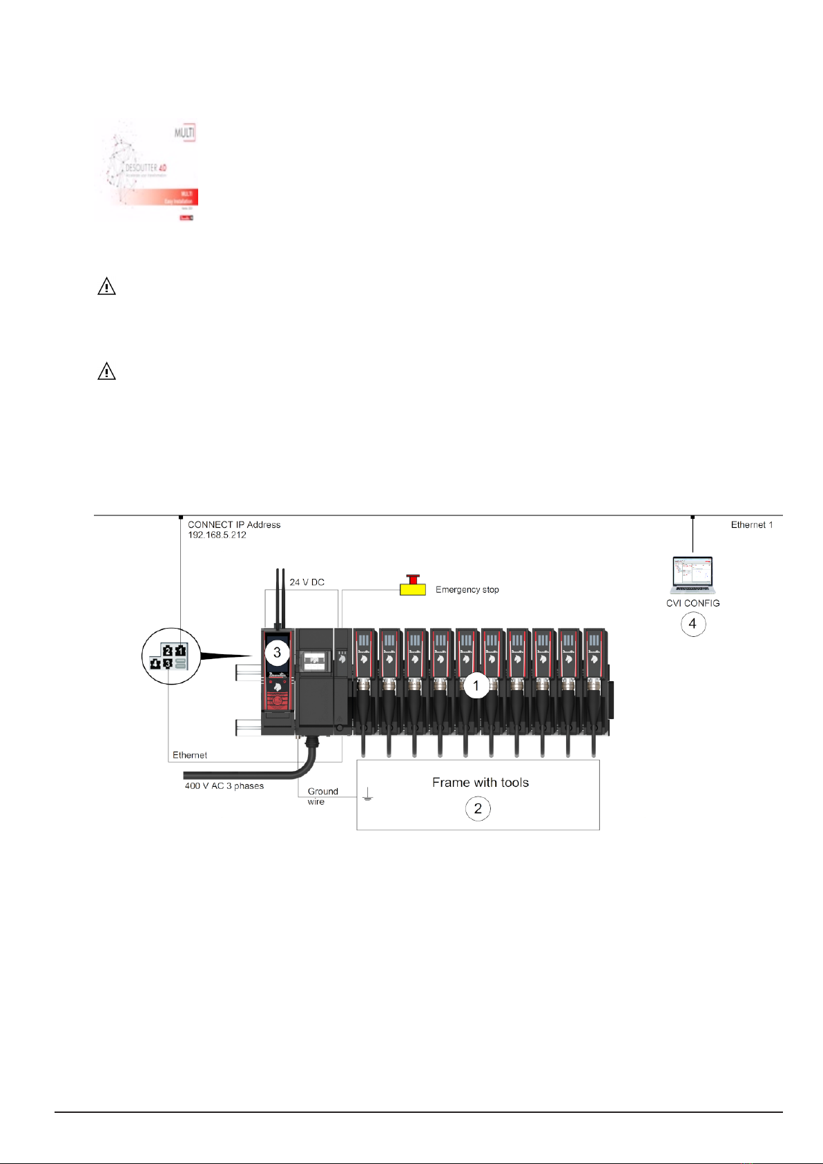
System description ..........................................................................................................................5
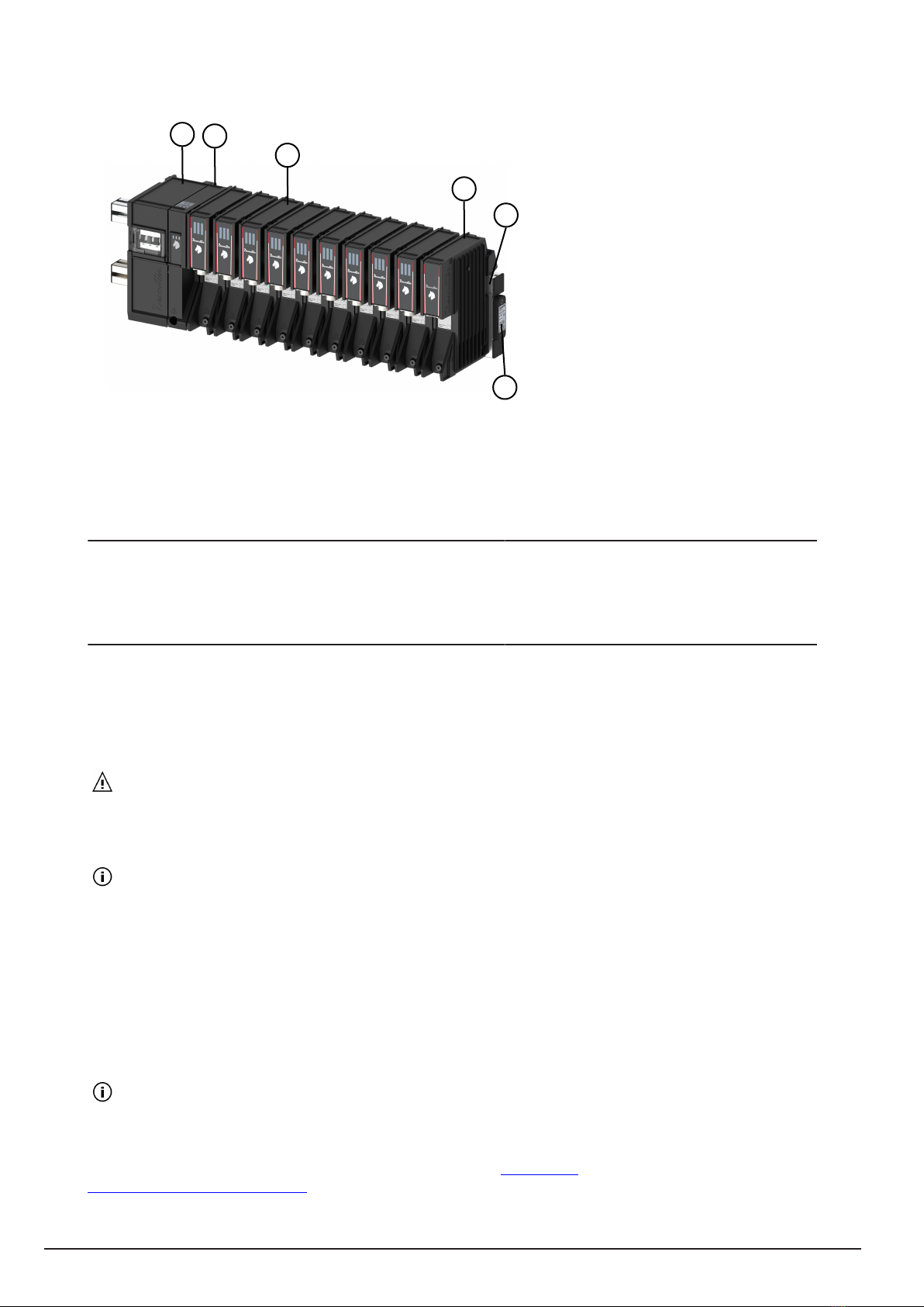
Overview ..............................................................................................................................5
Technical data......................................................................................................................8
Installation restrictions .......................................................................................................................10
Checking the line voltage ..............................................................................................................10
Connecting to factory power network ............................................................................................10
Permanently connected equipment...............................................................................................11
Overall dimensions........................................................................................................................11
Hardware installation ..........................................................................................................................13
Installing the system......................................................................................................................13
Recommended installation order .......................................................................................13
Mounting the aluminum profiles .........................................................................................13
Opening M-POWERBOX ...................................................................................................15
Mounting M-POWERBOX ..................................................................................................15
Connecting the power input ...............................................................................................15
Closing M-POWERBOX.....................................................................................................18
Connecting the power distribution cable to the mains........................................................18
Mounting M-MODURACK ..................................................................................................18
Managing multiple racks ....................................................................................................20
Mounting M-SAFETYBOX..................................................................................................21
Mounting M-DRIVE ............................................................................................................21
Mounting M-PROTECTRACK ............................................................................................21
Mounting CONNECT..........................................................................................................22
Installing cord fixtured tools................................................................................................23
Connecting the system..................................................................................................................25
M-SAFETYBOX - bottom panel .........................................................................................25
Connecting the Emergency stop ........................................................................................25
Connecting CONNECT to M-SAFETYBOX .......................................................................26
Connecting cord fixtured tools............................................................................................27
Connecting a computer to CONNECT ...............................................................................29
Powering on ..................................................................................................................................29
Powering off M-POWERBOX.............................................................................................29
Powering on the distribution circuit-breaker .......................................................................29
Powering on M-POWERBOX and CONNECT ...................................................................30
Reporting LEDs at powering on .........................................................................................30
Software installation ...........................................................................................................................31
Read before installing software .....................................................................................................31
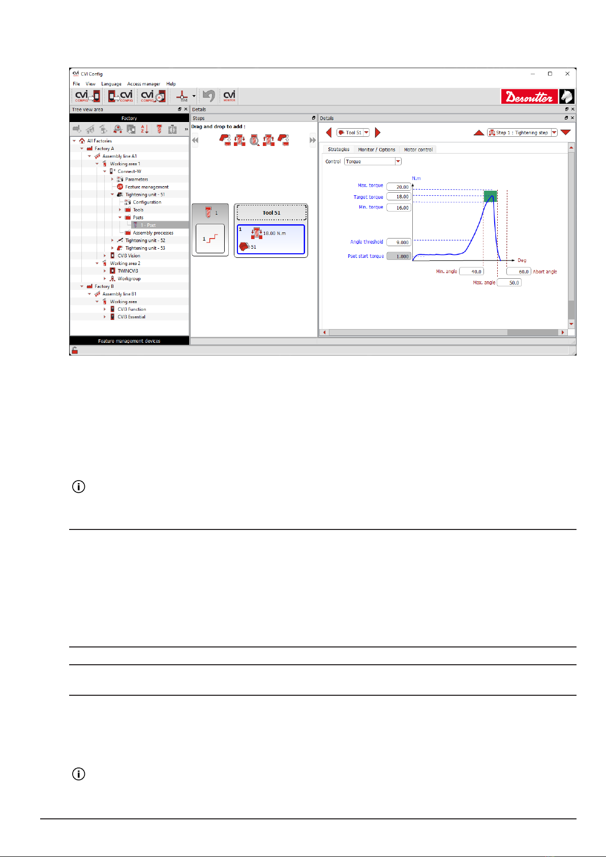
Location of Desoutter programs.........................................................................................31
Computer minimum requirements......................................................................................31

03/2023 3 / 64 6159929540 / v.03
Installing CVI CONFIG ..................................................................................................................31
Test and validate installation .............................................................................................................32
Testing and validating ...................................................................................................................32
Setting up MULTI in CVI CONFIG .....................................................................................32
Setting up the tools ............................................................................................................34
Configuring a Pset..............................................................................................................34
Updating CONNECT ..........................................................................................................35
Testing a Pset with CVI MONITOR....................................................................................35
Activating the Emergency stop system ..............................................................................36
Hardware upgrade ...............................................................................................................................37
Upgrading CONNECT ...................................................................................................................37
Checking the existing system firmware..............................................................................37
Checking the firmware version with CVIMONITOR ...........................................................37
Upgrading the firmware......................................................................................................37
Software upgrade ................................................................................................................................38
Upgrading software .......................................................................................................................38
References ...........................................................................................................................................39
Logical input ..................................................................................................................................39
General commands............................................................................................................39
Tool commands..................................................................................................................41
Pset commands .................................................................................................................42
Assembly Process commands ...........................................................................................42
External input .....................................................................................................................43
Socket tray .........................................................................................................................43
Customized Protocol commands .......................................................................................43
CVILOGIX ..........................................................................................................................44
List of user infos ............................................................................................................................44
List of user infos related to the system...............................................................................44
List of user infos related to the tools ..................................................................................53
Logical output ................................................................................................................................56
General status....................................................................................................................56
Tool status..........................................................................................................................57
Pset status .........................................................................................................................59
Assemby Process status....................................................................................................61
External output ...................................................................................................................62
Socket tray .........................................................................................................................62
Customized Protocol Status...............................................................................................62
CVILOGIX ..........................................................................................................................63
Miscellaneous ....................................................................................................................63

6159929540 / v.03 4 / 64 03/2023
Introduction
About Installation and Upgrade manual
This manual describes how to install and upgrade MULTI system.
Desoutter should not be held responsible for any injury, accident or damage which may be the consequence of an in-
correct installation, modification or start-up, or a use out of the intended use of Desoutter products, by the customer
or a third party.
Before starting, you must read and understand the safety instructions given in the booklet supplied in the pack-
aging box of products (printed matter: 6159929530).
At the end of the installation, the tool status is "Tool locked", awaiting the selection of the tightening operation
named "Pset".
To test and validate that the system is properly working, follow the procedure described in this manual.
Warranty
• Product warranty will expire 12 months after the product is first taken into use, but will in any case expire at the
latest 13 months after delivery.
• Normal wear and tear on parts is not included within the warranty.
• Normal wear and tear is that which requires a part change or other adjustment/overhaul during standard tools
maintenance typical for that period (expressed in time, operation hours or otherwise).
• The product warranty relies on the correct use, maintenance, and repair of the tool and its component parts.
• Damage to parts that occurs as a result of inadequate maintenance or performed by parties other than Desoutter
or their Certified Service Partners during the warranty period is not covered by the warranty.
• To avoid damage or destruction of tool parts, service the tool according to the recommended maintenance sched-
ules and follow the correct instructions.
• Warranty repairs are only performed in Desoutter workshops or by Certified Service Partners.
Desoutter offers extended warranty and state of the art preventive maintenance through its Tool Care contracts. For
further information contact your local Service representative.
For electrical motors:
• Warranty will only apply when the electric motor has not been opened.

03/2023 5 / 64 6159929540 / v.03
Quick Start
The following sections describe how to install your MULTI system
Read before installing
WARNING Read all safety warnings and all instructions. Failure to follow the warnings and instructions
may result in electric shock, fire and/or serious injury.
Save all warnings and instructions for future reference.
Refer to the "Safety Information" booklet provided in the product box.
WARNING All locally legislated safety rules regarding installation, operation and maintenance shall be
respected at all times.
System description
Overview
Example of installation with CONNECT-W and 10 M-DRIVE.
MULTI system is composed of the following items.
1. MULTI is providing the power supply, the connectivity and the safety devices.
2. The frame is equipped with cord fixtured tools designed by Desoutter.
3. CONNECT is managing the tightening units and all data communications.
4. CVI CONFIG is the software dedicated to set up the system.
Description
MULTI is composed of the following elements:
This manual suits for next models
8
Table of contents
Other Desoutter Industrial Equipment manuals

Desoutter
Desoutter DJS FOR DST AND PST 2Nm SOFT User manual

Desoutter
Desoutter Industrial Tools SD Series Operating instructions

Desoutter
Desoutter 115DFL User manual

Desoutter
Desoutter TRA 12 1600 P UNI User manual

Desoutter
Desoutter Industrial Tools SD Series Operating instructions

Desoutter
Desoutter B Series User manual

Desoutter
Desoutter EFDS Series User manual

Desoutter
Desoutter EMC FILTER User manual

Desoutter
Desoutter D53-5S User manual

Desoutter
Desoutter CP4444 User manual