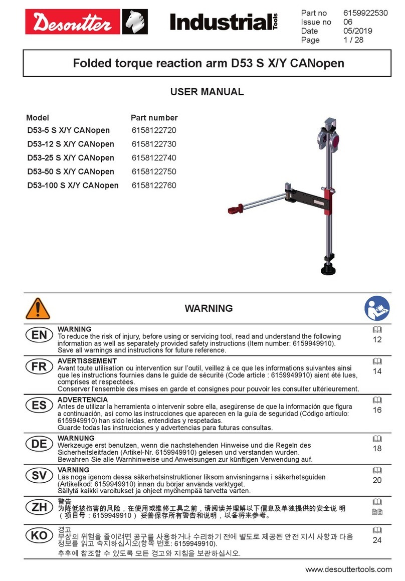
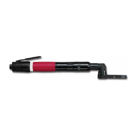
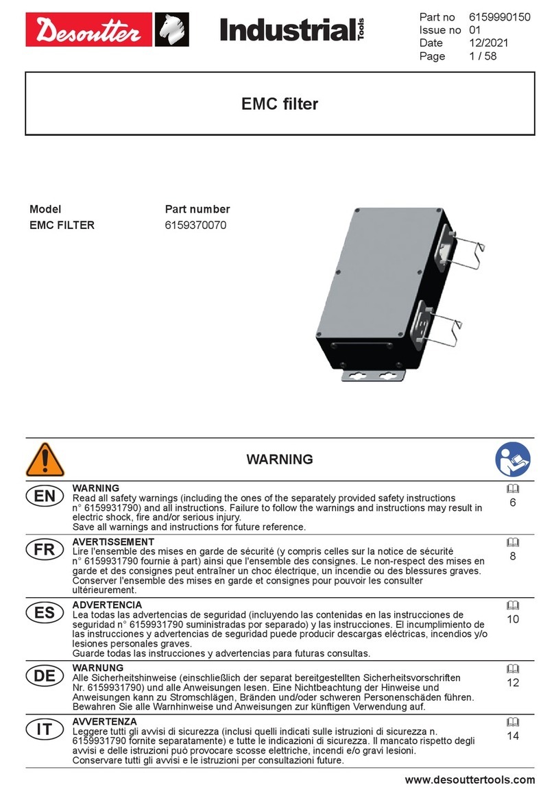
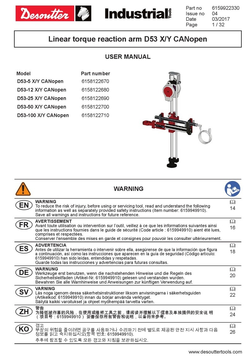
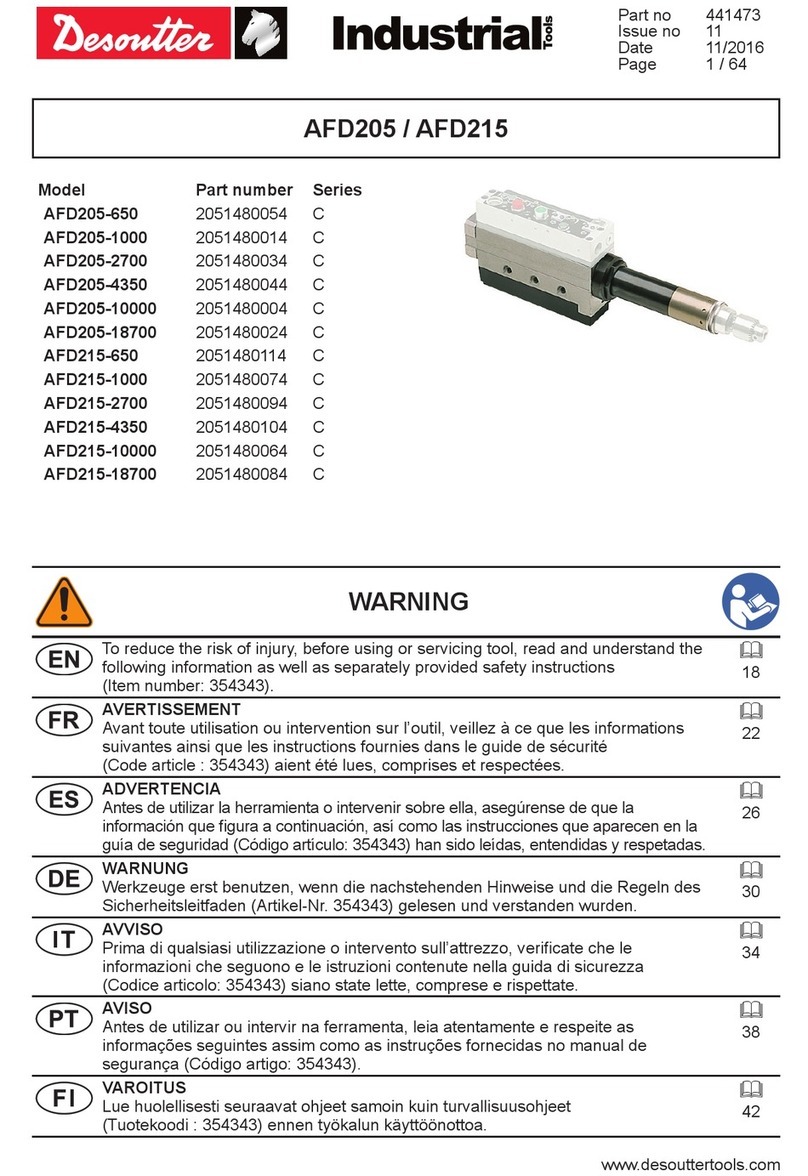
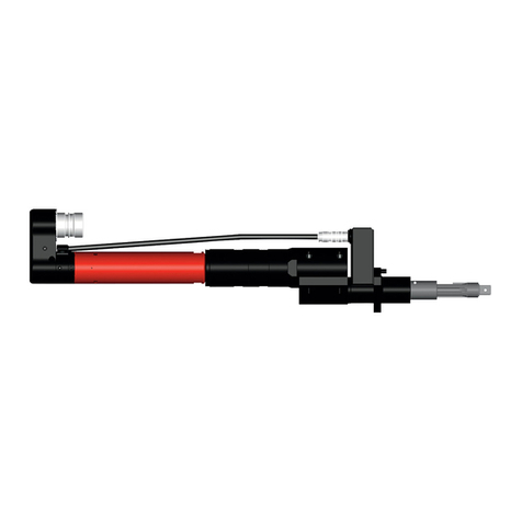
Desoutter TRA 12 1600 P UNI User manual

www.desouttertools.com
Part no 6159939310
Issue no 07
Date 11/2016
Page 1 / 60
WARNING
To reduce the risk of injury, before using or servicing tool, read and understand the
following information as well as separately provided safety instructions
(Item number: 6159949910).
14
AVERTISSEMENT
Avant toute utilisation ou intervention sur l’outil, veillez à ce que les informations
suivantes ainsi que les instructions fournies dans le guide de sécurité
(Code article : 6159949910) aient été lues, comprises et respectées.
16
ADVERTENCIA
Antes de utilizar la herramienta o intervenir sobre ella, asegúrense de que la
información que gura a continuación, así como las instrucciones que aparecen en
la guía de seguridad (Código artículo: 6159949910) han sido leídas, entendidas y
respetadas.
18
WARNUNG
Werkzeuge erst benutzen, wenn die nachstehenden Hinweise und die Regeln des
Sicherheitsleitfaden (Artikel-Nr. 6159949910) gelesen und verstanden wurden.
20
TRA 12 1600 P UNI 6158116940
TRA 25 2100 P UNI 6158116700
TRA 50 2100 P UNI 6158116760
TRA 100 2100 P 6158116820
TRA 200 2100 P 6158116880
TRA 12 1600 P2 UNI 6158116950
TRA 25 2100 P2 UNI 6158116710
TRA 50 2100 P2 UNI 6158116770
TRA 100 2100 P2 6158116830
TRA 200 2100 P2 6158116890
TRA 12 1600 P CANopen UNI 6158121020
TRA 25 2100 P CANopen UNI 6158121030
TRA 50 2100 P CANopen UNI 6158121040
TRA 100 2100 P CANopen 6158121050
TRA 200 2100 P CANopen 6158121060
TRA 12 1600 P2 CANopen UNI 6158121070
TRA 25 2100 P2 CANopen UNI 6158121080
TRA 50 2100 P2 CANopen UNI 6158121090
TRA 100 2100 P2 CANopen 6158121100
TRA 200 2100 P2 CANopen 6158121110
TRA P-P2 Torque reaction arm POSCO
TRA P-P2 CANopen Torque reaction arm CANopen
USER MANUAL

6159939310_07
2 / 60 11/2016
WARNING
AVVISO
Prima di qualsiasi utilizzazione o intervento sull’attrezzo, vericate che le informazioni
che seguono e le istruzioni contenute nella guida di sicurezza
(Codice articolo: 6159949910) siano state lette, comprese e rispettate.
22
AVISO
Antes de utilizar ou intervir na ferramenta, leia atentamente e respeite as informações
seguintes assim como as instruções fornecidas no manual de segurança
(Código artigo: 6159949910).
24
VAROITUS
Lue huolellisesti seuraavat ohjeet samoin kuin turvallisuusohjeet
(Tuotekoodi : 6159949910) ennen työkalun käyttöönottoa.
26
VARNING
Läs noga igenom dessa säkerhetsinstruktioner liksom anvisningarna i
säkerhetsguiden (Artikelkod: 6159949910) innan du börjar använda verktyget.
28
ADVARSEL
Før enhver bruk eller reparasjon av verktøyet skal de følgende instruksjonene og
forskriftene i sikkerhetsheftet (artikkelnummer: 6159949910) leses nøye.
30
VARELSE
Læs omhyggeligt, forstå og overhold disse instruktioner samt sikkerhedsforskrifterne
(Varenummer: 6159949910), inden værktøjet tages i brug eller repareres.
32
WAARSCHUWING
Voor gebruik of demontage van het gereedschap altijd eerst zekerstellen dat de
navolgende informatie evenals de geleverde veiligheidsinstructies
(Code artikel: 6159949910) gelezen, begrepen en in acht genomen zijn.
34
ΠΡΟΕΙΔΟΠΟΙΗΣΗ
Πριν από οποιαδήποτε χρήση ή επέμβαση στο εργαλείο, διαβάστε προσεκτικά,
κατανοήστε και τηρήστε τις παρακάτω πληροφορίες, καθώς και τις οδηγίες που
περιλαμβάνονται στο εγχειρίδιο ασφαλείας (Κωδικός προϊόντος: 6159949910).
36
警告
为降低被伤害的风险,在使用或维修工具之前,请阅读并理解以下信息及单
独提供的安全说 明 (项目号:6159949910)
38
VIGYÁZAT
A szerszám használata vagy bármilyen más beavatkozás előtt a felhasználónak el
kell olvasnia, meg kell értenie és a használat vagy beavatkozás során be kell tartania
a következő, valamint a biztonsági útmutatóban (cikkszám: 6159949910) szereplő
utasításokat.
40
BRĪDINĀJUMS
Lai mazinātu bīstamību, pirms apkopes instrumenta lietošanas jāizlasa un jāizprot
turpmākā informācija, kā arī atsevišķi dotie drošības tehnikas noteikumi (preces
numurs: 6159949910).
42
OSTRZEŻENIE
Przed podjęciem użytkowania przyrządu czy jakichkolwiek działań z nim związanych
– należy upewnić się, że instrukcje dostarczone razem z podręcznikiem d/s
bezpieczeństwa (Kod urządzenia: 6159949910) zostały przeczytane, zrozumiane i
będą przestrzegane.
44

6159939310_07
3 / 6011/2016
WARNING
VAROVÁNÍ
Aby nedošlo ke zranění, seznamte se před použitím či údržbou nástroje s
následujícími informacemi a zvlášt’dodávanými bezpečnostními pokyny
(kat.č. 6159949910).
46
UPOZORNENIE
Aby sa znížilo riziko poranenia, prečítajte si nasledujúce informácie, ako aj osobitne
priložené bezpečnostné opatrenia (položka číslo 6159949910) a snažte sa im
porozumiet’.
48
OPOZORILO
Zaradi morebitnih poškodb, pred uporabo ali servisiranjem orodja, preberite in
upoštevajte naslednje informacije, kakor tudi posebej priložena varnostna navodila
(postavka št.: 6159949910).
50
ĮSPĖJIMAS
Siekiant sumažinti sužeidimo pavojų, prieš naudodami arba taisydami įrankį
perskaitykite ir įsidėmėkite toliau išdėstytą informaciją, o taip pat ir atskirai pateiktas
saugos instrukcijas (dalies numeris: 6159949910).
52
ПРЕДУПРЕЖДЕНИЕ
До использования или вмешательства на инструменте необходимо прочитать,
усвоить и соблюдать нижеследующую информацию, а также указания,
приведенные в пособии по технике безопасности (Артикул товара : 6159949910).
54
Find more information and your Desoutter contacts on:
Software and documentation available at:
www.desouttertools.com
http://resource-center.desouttertools.com
No login/password required.

6159939310_07
4 / 60 11/2016
TECHNICAL DATA
Model Part number Torque Max* L min* L max*
(Nm) (ft.lb) (mm) (in) (mm) (in)
TRA 12 1600 P UNI 6158116940 12 8.9 883,5 34,78 1762 69,4
TRA 25 2100 P UNI 6158116700 25 18.4 1053,5 41,47 2259 88,9
TRA 50 2100 P UNI 6158116760 50 36.9 1105 43,5 2311 91
TRA 100 2100 P 6158116820 100 73.8 1080 42,5 2315 91,15
TRA 200 2100 P 6158116880 200 148 1085 42,7 2317 91,2
TRA 12 1600 P2 UNI 6158116950 12 8.9 883,5 34,78 1762 69,4
TRA 25 2100 P2 UNI 6158116710 25 18.4 1053,5 41,47 2259 88,9
TRA 50 2100 P2 UNI 6158116770 50 36.9 1105 43,5 2311 91
TRA 100 2100 P2 6158116830 100 73.8 1080 42,5 2315 91,15
TRA 200 2100 P2 6158116890 200 148 1085 42,7 2317 91,2
* : Idem for CANopen version
Model Part number Stroke* Weight*
(mm) (in) (kg) (lb)
TRA 12 1600 P UNI 6158116940 878,5 34.6 4 8.8
TRA 25 2100 P UNI 6158116700 1205,5 47.5 4,2 9.3
TRA 50 2100 P UNI 6158116760 1206 47.5 4,6 10.1
TRA 100 2100 P 6158116820 1235 48.6 4,8 10.6
TRA 200 2100 P 6158116880 1232 48.5 6,4 14.1
TRA 12 1600 P2 UNI 6158116950 878,5 34.6 4,2 9.3
TRA 25 2100 P2 UNI 6158116710 1205,5 47.5 4,4 9.7
TRA 50 2100 P2 UNI 6158116770 1206 47.5 4,8 10.6
TRA 100 2100 P2 6158116830 1235 48.6 5 11
TRA 200 2100 P2 6158116890 1232 48.5 6,8 15
* : Idem for CANopen version
L
L
S
S
TRA 12 - 25 - 50
TRA 100 - 200

6159939310_07
5 / 6011/2016
CANopen CONNECTION
Item 11 - Male connector M12
Item 13 - Male connector M12
eBUS SubD9-pt M12 extension cable
Screen connected to encoder housing and connector housing
Pin Signal
1 n.c.
2 +V
3 CAN_GND
4 CAN_H
5 CAN_L
Pin Signal
1 CAN_GND
2 +V
3 0 V
4 CAN_H
5 CAN_L
Length
mPart number
3 6159176620
10 6159176630
PLC
Shield connection
11
13
5
CAN_L
4
RED
BLACK
WHITE
BLUE
SHIELD
CAN_H
3
V-
M12 2
V+
4x0,2 qmm
2 m
1
SH
eBUS
SubD-9pt 1 2 374

6159939310_07
6 / 60 11/2016
WORKING AREA
Horizontal, side view
Horizontal, top view
TRA P βMax = 240°
TRA P2 βMax = 205°
Working area
L min
L max
β
TRA P Max 240° - TRA P2 Max 205°
Working area
Working area
S
L min
L max
0
+75°
-75°
Let the
articulation free

6159939310_07
7 / 6011/2016
150°
Working area
Working area
L min
L max
S
+75° 0 -75°
Let the articulation free
WORKING AREA
Vertical, side view
Vertical, back view

6159939310_07
8 / 60 11/2016
SPARE PARTS
14 16
1512 13
P2 version = + + + + +
1
12
13
11
16
9
10
10
14
7
8
15
1
3
2
3
54
19
17
18
20

6159939310_07
9 / 6011/2016
Item Part number Qty Description For arm
1 - 5 6158101920 1 Wear part kit -
1 - 2 Plastic washer 14x8.1x1 Nylon TRA12 / TRA 25
1 - 2 Plastic washer 20x12.1x2 Nylon TRA 50 / TRA 100
1 - 2 Plastic washer 26x17.2x1,4 Nylon TRA 200
2 - 2 Plastic washer 14x8.1x1 Nylon TRA12 / TRA 25
2 - 2 Plastic washer 14x8.1x1 Nylon TRA 50
2 - 2 Plastic washer 17x10,2.1x2 Nylon TRA 100
2 - 2 Plastic washer 20x12.1x2 Nylon TRA 200
3 - 2 Set screw M5x5 -
4 - 1 Steel washer 6.4x12x1.6 TRA 25
4 - 1 Steel washer 8.4x16x1.6 TRA 50
4 - 1 Steel washer 10.5x20x2 TRA 100
5 - 1 Lock nut M5 TRA 12
5 - 1 Lock nut M6 TRA 25
5 - 1 Lock nut M8 TRA 50
5 - 1 Lock nut M10 TRA 100
5 - 1 Lock nut M12 TRA 200
6 - 1 Lock nut pal M6 TRA12-25-50 P-P2
6 - 1 Lock nut pal M8 TRA100 P-P2
6 - 1 Lock nut pal M10 TRA200 P-P2
7 6158117030 1 Encoder support top TRA 12 P-P2
7 6158117060 1 Encoder support top TRA 25 P-P2
7 6158117080 1 Encoder support top TRA 50 P-P2
7 6158117100 1 Encoder support top TRA 100 P-P2
7 6158117120 1 Encoder support top TRA 200 P-P2
8 6158117040 1 Encoder support middle TRA 12-25-50-100 P-P2
8 6158117130 1 Encoder support middle TRA200 P-P2
9 6158117050 1 Encoder support bottom TRA12 P-P2
9 6158117070 1 Encoder support bottom TRA25 P-P2
9 6158117090 1 Encoder support bottom TRA50 P-P2
9 6158117110 1 Encoder support bottom TRA100 P-P2
9 6158117140 1 Encoder support bottom TRA200 P-P2
10 6158117150 2 Special screw TRA12-25-50 P-P2
10 6158117520 2 Special screw TRA100 P-P2
10 6158117170 2 Special screw TRA200 P-P2
11 6158116570 1 Encoder cable SSI TRA P-P2
11 6158119850 1 Encoder cable CANopen TRA P-P2
12 6158117390 1 Encoder shaft TRA 12 P2
12 6158117400 1 Encoder shaft TRA 25 P2
12 6158117410 1 Encoder shaft TRA 50 P2
12 6158117420 1 Encoder shaft TRA 100 P2
12 6158117430 1 Encoder shaft TRA 200 P2

6159939310_07
10 / 60 11/2016
BALANCER DEFINITION
Tool Clamp TRA Arm Balancer
kg
(Lb)
kg
(Lb)
kg
(Lb) TRA12 TRA25 TRA50 TRA100 TRA200 kg
(Lb)
+ + 0,15
(0.33)
0,3
(0.66)
0,5
(1.1)
0,7
(1.54)
1
(2.2) =
←?
Item Part number Qty Description For arm
13 6158116530 1 Encoder rotary analogue TRA P2
13 6158119840 1 Encoder rotary CANopen TRA P2
14 6158117505 1 Bracket stop rotary encoder kit TRA P2
15 - 1 Cylindrical pin 4X12 -
16 - 1 Screw hex head cap M3x12 -
17 6158121150 1 Connector H TRA P-P2 CANopen
18 6158121160 1 Resistor end line TRA P-P2 CANopen
19 6158121170 1 Support connector H TRA P-P2 CANopen
20 - 2 Screw M4x35 TRA P-P2 CANopen
INSTALLATION
Let the articulation free

6159939310_07
11 / 6011/2016
OPTIONAL ACCESSORIES
5.7 Nm 9.8 Nm
33 Nm24 Nm 9.8 Nm
4 5
3
2
678910
11 12 13 14
Item Part number Qty Description
1 6153979225 1 Balancer adapter kit
2 - 1 Adaptor
3 - 1 Adaptor
4 - 1 Washer
5 - 1 Washer 6.4X12X1.6 FZB
6 - 1 Hex sock screw MC 6S M6X18 8.8
7 - 1 Adaptor
8 - 1 Adaptor
9 - 1 Washer 8.4X16X1.6 FZB HV 200-300
10 - 1 Hex sock screw MC 6S M8X100 12.9
11 - 1 Spacing nut M5X19, A/F 10
12 - 1 Screw eye M5X25. For TRA 12/25/50 P-P2
13 - 1 Spacing nut M6X19, A/F 13
14 - 1 Screw eye M6X25. For TRA 100/200 P-P2

6159939310_07
12 / 60 11/2016
OPTIONAL ACCESSORIES
Item Part number Description Comment
1 6158101210 Bench stand holder Ø 32mm (1.26") For arm TRA 12 P-P2/ TRA 25 P-P2
1 6158101400 Bench stand holder Ø 32mm (1.26") For arm TRA 50 P-P2/ TRA 100 P-P2
2 6158101940 Bench stand Ø 32mm (1.26") Height: 753 mm (29.64")
3 6158101930 Heavy duty table stand clamp Dimension: 22 - 82 mm (0.87 - 3.22")
TRA 200 should not be used with table stand.
1
2
3

6159939310_07
13 / 6011/2016
OPTIONAL ACCESSORIES
Item Part number Description Diameter Weight For arm
(mm) (in) (kg) (lb)
A 6158101180 Universal tool holder 28 1.1 0.087 0.192 TRA 12 P-P2
TRA 25 P-P2
49 1.93
B 6158101370 Universal tool holder 28 1.1 0.192 0.423 TRA 50 P-P2
TRA 100 P-P2
50 1.97
C 6158110290 Universal tool holder 28 1.1 0.556 1.225 TRA 50 P-P2
TRA 100 P-P2
55 2.16
D 6158101250 Tool holder 34 1.34 0.043 0.095 TRA 12 P-P2
TRA 25 P-P2
6158101270 36.5 1.44 0.046 0.101
6158101290 38 1.5 0.042 0.093
6158101310 44 1.73 0.056 0.123
For TRA 100 use only as tool support not
for torque reaction.
Item Part number Description For tool Spline Weight For arm
(kg) (lb)
E 6158102020 Tool holder ERDL4/ECD120 G1 / Ø 40.5 0.290 0.639 TRA 200 P-P2
F 6158102030 Tool holder ERDL4/ECD50/
ECD70 G1 / Ø 40.5 0.131 0.288 TRA 50 P-P2
TRA 100 P-P2
F 6158121360 Tool holder EID44-65-75
G 6158102040 Tool holder ERDL6 G1 / Ø 50 0.458 1 TRA 200 P-P2
H 6158102050 Tool holder ERDL6 G1 / Ø 50 0.219 0.482 TRA 50 P-P2
TRA 100 P-P2
I 6158106280 Tool holder - To weld 0.219 0.482 TRA 50 P-P2
TRA 100 P-P2
J 6158106310 Tool holder - To weld 0.900 2 TRA 200 P-P2
E F G H I J
A B C D

14 / 60
English
11/2016
6159939310_07
Original instructions.
© Copyright 2016, Ets Georges Renault 44818
St Herblain, FR
All rights reserved. Any unauthorized use
or copying of the contents or part thereof
is prohibited. This applies in particular to
trademarks, model denominations, part numbers
and drawings. Use only authorized parts. Any
damage or malfunction caused by the use of
unauthorised parts is not covered by Warranty or
Product Liability.
STATEMENT OF USE
This product is designed for holding power tools
within the specied load / torque capacity.
No other use permitted.
For professional use only.
The torque arms TRA Series P and P2 equipped
with encoders connected to Posco 500 or other
controller can detect the screw position during a
tightening cycle.
It is recommended to use the TRA series
of arms together with a balancer.
INSTRUCTIONS
● To learn how to congure the arm
as a positioning arm by using CVI
CONFIG software and CVI3 Vision
controller, refer to the user manual
6159923060 available at http://
resourcecenter.desouttertools.com.
Torque arm attachment
●The torque arm should be installed straight in
front of the operator or to the right of a right
handed operator if the arm is used with the
bench stand.
●Search for the best position.
● The bench stand is predrilled for xing to the
bench.
●An optional clamp can be used during the
search for the permanent installation.
● Tighten the screw in the holder rmly.
●If the arm is mounted in the ceiling the
mounting point should be straight above, or
as close to as possible, the point where the
torque is applied.
● The xation screw has to be Class 12.9
● Make sure that the xation support can
support the weight and the torque of the
chosen torque arm.
● To x the auxiliary cable to a second
attachment point.
Attachment and balancing of the tool
(mounted on bench stand)
TRA 200 should not be used with bench
stand.
●Adjust the height of the arm relative to the
work piece. It is recommended to mount the
arm attachment at the same height as where
the torque is applied.
●Attach the tool holder to the tool.
●Attach the tool holder to the arm.
●Balance the tool with the balancer.
●Finally secure the bench stand to the bench
and tighten all the set screws.
Attachment and balancing of the tool
(mounted in the ceiling)
●Mount the arm straight above, or as close
to as possible, the point where the torque is
applied.
●Attach the tool holder to the tool.
●Attach the tool holder to the arm.
●Attach a balancer in the ceiling adjacent to the
arm and hook it up with the tool.
●Adjust the balancer so it takes up the weight
of the arm, tool holder and the tool.
●Finally secure all the screws with the set
screws.
MAINTENANCE INSTRUCTIONS
Maintenance should be performed by qualied
personnel only.
●Prior to any maintenance task: disconnect the
tool.
●The bench stand pole should be lubricated
with a couple of drops of oil twice a year.
●The bushings on the arms do not need any
lubrication.
When disposing of components,
lubricants, etc … ensure that the
relevant safety procedures are carried
out.
DESOUTTER WARRANTY
1. This Desoutter product is warranted against
defective workmanship or materials, for a
maximum period of 12 months following the
date of purchase from Desoutter or its agents,
provided that its usage is limited to single shift
operation throughout that period. If the usage
rate exceeds that of single shift operation, the
warranty period shall be reduced on a prorata
basis.
2. If, during the warranty period, the product
appears to be defective in workmanship or
materials, it should be returned to Desoutter
or its agents, together with a short description

15 / 60
English
11/2016
6159939310_07
of the alleged defect. Desoutter shall, at its
sole discretion, arrange to repair or replace
free of charge such items as are deemed
faulty by reason of defective workmanship or
materials.
3. This warranty ceases to apply to products
which have been abused, misused or
modied, or which have been repaired using
other than genuine Desoutter spare parts
or by someone other than Desoutter or its
authorized service agents.
4. Should Desoutter incur any expense
correcting a defect resulting from abuse,
misuse, accidental damage or unauthorized
modication, they will require that such
expense shall be defrayed in full.
5. Desoutter accepts no claim for labour or other
expenditure made upon defective products.
6. Any direct, incidental or consequential
damages whatsoever arising from any defect
are expressly excluded.
7. This warranty is given in lieu of all other
warranties, or conditions, expressed or
implied, as to the quality, merchantability or
tness for any particular purpose.
8. No one, whether an agent, servant or
employee of Desoutter, is authorized to add to
or modify the terms of this limited warranty in
any way.

Français
(French)
16 / 60 11/2016
6159939310_07
Instructions originales.
© Copyright 2016, Ets Georges Renault 44818
St Herblain, FR
Tous droits réservés. Tout usage illicite ou copie
totale ou partielle sont interdits. Ceci s’applique
plus particulièrement aux marques déposées,
dénominations de modèles, numéros de
pièces et schémas. Utiliser exclusivement les
pièces autorisées. Tout dommage ou mauvais
fonctionnement causé par l’utilisation d’une
pièce non autorisée ne sera pas couvert par la
garantie du produit et le fabricant ne sera pas
responsable.
DÉCLARATION D'UTILISATION
Ce produit est conçu pour supporter un outil
électrique dans les limites des capacités de
charge et de couple préconisées.
Aucune autre utilisation autorisée.
Pour usage professionnel uniquement.
Les bras de réaction de la série TRA P et P2
équipés d’encodeurs connectés au Posco 500
ou autre controleur permettent de détecter la
position de la vis au cours d’un cycle de vissage.
Il est recommandé d'associer les bras de
la série TRA avec un équilibreur.
INSTRUCTIONS
Fixation du bras de réaction
●Le bras de réaction doit être installé
exactement en face de l'opérateur ou à droite
d'un opérateur droitier s'il est utilisé avec le
support d'établi.
●Rechercher la meilleure position.
●Le support d'établi est pré-percé pour
permettre sa xation sur l'établi.
●Au besoin, on pourra utiliser un serre-joint
le temps de trouver la position d'installation
dénitive.
●Serrer fermement la vis du support.
● Si le bras est xé au plafond, le point de
xation doit se trouver exactement à la
verticale, ou le plus près possible, de l'endroit
où le couple est appliqué.
● Les vis de xation doivent être de Classe
12.9.
● S’assurer que le support de xation peut
supporter le poids et le couple du bras choisi.
●Fixer le câble auxiliaire à un second point
d’attache.
Fixation et équilibrage de l'outil (montage sur
le support d'établi)
Le TRA 200 ne doit pas être utilisé avec
le support d’établi.
●Régler la hauteur du bras par rapport à la
pièce à travailler. Il est recommandé de placer
la xation du bras à la même hauteur que
l'endroit où le couple est appliqué.
●Fixer le support d'outil sur l'outil.
●Fixer le support d'outil sur le bras.
●Équilibrer l'outil au moyen du dispositif
d'équilibrage.
● Enn, xer le support d'établi sur l'établi et
serrer toutes les vis de blocage.
Fixation et équilibrage de l'outil (montage au
plafond)
●Fixer le bras exactement à la verticale, ou le
plus près possible, de l'endroit où le couple
est appliqué.
●Fixer le support d'outil sur l'outil.
●Fixer le support d'outil sur le bras.
●Attacher un équilibreur au plafond à côté du
bras et l'accrocher à l'outil.
●Régler l'équilibreur de façon à ce qu'il
reprenne le poids du bras, du support d'outil
et de l'outil.
● Enn, bloquer toutes les vis au moyen des vis
de blocage.
INSTRUCTIONS D’ENTRETIEN
La maintenance doit être assurée par du
personnel qualié uniquement.
●Avant toute opération de maintenance,
débrancher l’outil.
● La perche du support d'établi doit être lubriée
avec une ou deux gouttes d'huile par an.
●Les bagues des bras ne nécessitent aucune
lubrication.
Pour l’élimination des composants,
lubriants, etc… assurez vous que
les procédures de sécurité soient
respectées.
GARANTIE DESOUTTER
1. Ce produit Desoutter est garanti contre les
vices de main d’oeuvre ou de fabrication,
pendant une période maximum de 12 mois
à compter de la date d’achat auprès de
Desoutter ou de ses agents, dans la mesure
où son usage est limité à une seule équipe
de travail pendant cette période. Si le taux
d’utilisation excède celui d’une seule équipe
de travail, la période de garantie sera réduite
proportionnellement.

Français
(French)
17 / 6011/2016
6159939310_07
2. Si, pendant la période de garantie, le
produit semble présenter des vices de
main d’oeuvre ou de fabrication, il doit être
renvoyé à Desoutter ou à ses agents avec
une description courte du défaut constaté.
Desoutter, à sa seule discrétion, organisera
la réparation ou le remplacement gratuit des
articles jugés défectueux pour cause de vice
de main d’oeuvre ou de fabrication.
3. Cette garantie sera annulée s’il y a eu abus,
mauvaise utilisation ou modication des
produits, ou s’ils ont été réparés en utilisant
des pièces de rechange autres que celles
prescrites par Desoutter ou par une personne
autre que Desoutter ou l’un de ses agents
agréés.
4. Au cas où Desoutter encourrait des dépenses
pour rectier un défaut résultant d’abus,
de mauvaise utilisation, de détérioration
accidentelle ou de modication non autorisée,
ces dépenses seront à la charge totale du
client.
5. Desoutter n’accepte aucune réclamation
en termes de main d’oeuvre ou d’autres
dépenses effectuées sur les produits
défectueux.
6. Toutes les détériorations directes,
accidentelles ou indirectes, quelles qu’elles
soient, provenant d’un défaut quelconque,
sont expressément exclues.
7. Cette garantie remplace toutes les autres
garanties ou conditions, expresses
ou implicites, quant à la qualité, la
commercialisation ou l’adéquation du produit
pour un objectif particulier.
8. Personne, que ce soit un agent, un serviteur
ou un employé de Desoutter, n’est autorisé à
ajouter ou modier d’une façon quelconque
les termes de cette garantie limitée.

18 / 60
Español
(Spanish)
11/2016
6159939310_07
Instrucciones originales.
© Copyright 2016, Ets Georges Renault 44818
St Herblain, FR
Reservados todos los derechos. Está prohibido
todo uso indebido o copia de este documento o
parte del mismo. Esto se reere especialmente
a marcas comerciales, denominaciones de
modelos, números de piezas y dibujos. Utilicen
exclusivamente piezas de repuesto autorizadas.
Cualquier daño o defecto de funcionamiento
causado por el uso de piezas no autorizadas
queda excluído de la garantía o responsabilidad
del fabricante.
DECLARACIÓN DE USO
Este producto ha sido diseñado para la sujeción
de herramientas motorizadas dentro de la carga /
par especicados.
No se permite ningún otro uso.
Sólo para uso profesional.
Los brazos TRA Serie P y P2 están equipados
con encoders conectados al Posco 500 o a otro
controlador puede detectar la posición del tornillo
durante el ciclo de ensamblaje.
Se recomienda utilizar la serie de brazos
TRA junto con un compensador.
INSTALACIÓN
Acople del brazo jo
●El brazo de reacción debe instalarse en
posición recta, frente al operario o bien, a la
derecha si el operario es diestro si se usa el
brazo con un soporte de banco.
●Busque la mejor posición.
● El soporte del banco posee oricios pre-
perforados para su jación al banco de
trabajo.
●Disponemos de una sujeción opcional para
utilizar durante las pruebas para buscar la
posición permanente de instalación.
● Apriete el tornillo al soporte con rmeza.
●Si el brazo se monta en el techo, el punto de
montaje debe estar justo encima, o tan cerca
como sea posible, del punto donde se aplica
el par.
● El tornillo de jación debe ser de clase 12,9
● Asegúrese de que el soporte de jación
aguanta el peso y par del brazo seleccionado
● Para jar el cable auxiliar a un segundo punto
de jación.
Sujeción y equilibrado de la herramienta
(montada en soporte de banco)
La TRA 200 no debe usarse con soporte
de banco.
●Ajuste la altura del brazo en relación a la
pieza de trabajo. SE recomienda montar el
accesorio del brazo a la altura a la que se
aplica el par.
●Sujete la herramienta en el soporte.
●Sujete la herramienta en el brazo.
●Equilibre la herramienta con el compensador.
● Por último, je el soporte del banco al banco y
apriete todos los tornillos de jación.
Sujeción y equilibrado de la herramienta
(montada en el techo)
●Monte el brazo justo encima, o tan cerca
como sea posible, del punto donde se aplica
el par.
●Sujete la herramienta en el soporte.
●Sujete la herramienta en el brazo.
●Coloque un compensador en el techo al lado
del brazo y engánchelo con la herramienta.
●Ajuste el compensador de forma que
soporte el peso del brazo, del soporte de la
herramienta y de la herramienta.
●Por último asegure todos los tornillos con los
tornillos de jación.
INSTRUCCIONES DE MANTENIMIENTO
Las operaciones de mantenimiento las efectuará
exclusivamente personal cualicado.
●Antes de cualquier operación de
mantenimiento: desconecten la herramienta.
●The bench stand pole should be lubricated
with a couple of drops of oil twice a year.
●The bushings on the arms do not need any
lubrication.
Para la eliminación de los
componentes, lubricantes, etc…
comprueben que las normas de
seguridad han sido respetadas.
GARANTÍA DESOUTTER
1. Este producto Desoutter se garantiza contra
materiales o mano de obra defectuosos,
durante un período máximo de 12 meses
a partir de la fecha de compra ya sea a
Desoutter o a cualquiera de sus agentes,
siempre que se limite su uso a un solo
turno de trabajo durante dicho período. Si el
promedio de uso excede el de un turno de
trabajo normal, se reducirá proporcionalmente
el período de la garantía.

19 / 60
Español
(Spanish)
11/2016
6159939310_07
2. Si durante el período de garantía, el producto
presenta algún defecto en cuanto a materiales
o mano de obra, deberá ser devuelto a
Desoutter o a cualquiera de sus agentes,
junto con una breve descripción del defecto.
A su sola discreción, Desoutter podrá decidir
reparar o sustituir gratuitamente aquellos
elementos para los que considere que hay un
vicio de material o mano de obra.
3. La presente garantía no se aplica en caso de
abuso, mal uso, modicación, o reparación
con repuestos que no sean piezas auténticas
Desoutter, o si han sido reperados por
personal ajeno a Desoutter o cualquiera de
sus agentes autorizados.
4. Aquellos gastos a los que Desoutter tuviese
que hacer frente para corregir un defecto
debido al abuso, mal uso o modicación no
autorizada, correrán íntegramente por cuenta
del cliente.
5. Desoutter no acepta reclamación alguna en
concepto de mano de obra u otros gastos
efectuados en productos defectuosos.
6. Todos aquellos daños directos, accidentales
o indirectos, sea cual sea su naturaleza,
que resultasen de cualquier defecto serán
expresamente excluidos.
7. Esta garantía sustituye a cualquier otra
garantía, o condiciones, expresas o implícitas,
referente a calidad, comercialización o
adecuación del producto para un determinado
objetivo.
8. Nadie, ya sea un agente, prestatario o
empleado de Desoutter, está autorizado a
añadir o modicar los términos de la presente
garantía limitada.

20 / 60
Deutsch
(German)
11/2016
6159939310_07
Ursprüngliche Betriebsanleitung.
© Copyright 2016, Ets Georges Renault 44818
St Herblain, FR
Alle Rechte vorbehalten. Unbefugtes Verwenden
oder Kopieren des Inhalts bzw. von Teilen des
Inhalts ist verboten. Dies gilt insbesondere
für Warenzeichen, Modellbezeichnungen,
Teilenummern und Zeichnungen. Nur die
zugelassenen Ersatzteile verwenden. Schäden
oder Funktionsstörungen, die durch die
Verwendung nicht zugelassener Ersatzteile
entstehen, sind von der Garantieleistung und der
Produkthaftung ausgeschlossen.
GEBRAUCHSANLEITUNG
Dieses Produkt ist zum Halten von
Elektrowerkzeugen innerhalb der spezizierten
Tragfähigkeit / Drehmomentkapazität orgesehen.
Kein anderes Gebrauch ist gestattet.
Nur für den industriellen Einsatz.
Werkzeugständer TRA Series P und P2,
ausgerüstet mit Encodern im Verbindung mit
Posco 500 oder andere Kontroller, können die
Schraubstellung während eines Anziehverfahren
erkennen.
Es wird empfohlen, die Drehmomentarme
der TRA-Reihe zusammen mit einem
Balancer zu verwenden
INSTALLATION
Befestigung des Drehmomentarms
●Der Drehmomentarm sollte in gerader Linie
vor dem Bediener oder bei Verwendung
mit einem Werkbankständer für einen
rechtshändigen Bediener auf der rechten
Seite montiert werden.
●Probieren Sie aus, welche Position für Sie
ideal ist.
●Der Werkbankständer verfügt über Bohrungen
zur Befestigung an der Werkbank.
●Bis die endgültige Montageposition feststeht,
kann eine zusätzliche Halteklammer
verwendet werden.
●Die Schraube in der Halterung fest anziehen.
●Wenn der Drehmomentarm an der
Decke montiert wird, muss sich der
Befestigungspunkt direkt oder möglichst
nahe über der Stelle benden, an der das
Drehmoment angelegt wird.
●Die Festigkeitklasse der Schraube muß 12.9
sein.
● Prüfen Sie dass, das Auager das Gewicht
und das Drehmoment des ausgewähltes
Werkzeugständers aufstehen kann
● Versichern das zusätzliches Kabel an einem
zweiten Befestigungspunkt.
Anbringen und Ausbalancieren des
Werkzeugs (an Werkbankständer montiert)
TRA 200 sollte nicht mit einem
Werkbankständer verwendet werden.
●Die Armhöhe relativ zum Werkstück einstellen.
Es wird empfohlen, die Armhalterung auf
derselben Höhe zu montieren, an der das
Drehmoment angelegt wird.
●Die Werkzeugaufnahme am Werkzeug
anbringen.
●Die Werkzeugaufnahme am Arm anbringen.
●Das Werkzeug mit dem Balancer
ausbalancieren.
●Zum Schluss den Werkbankständer sicher
an der Werkbank befestigen und alle
Stellschrauben anziehen.
Anbringen und Ausbalancieren des
Werkzeugs (an der Decke montiert)
●Den Arm direkt oder möglichst nahe über der
Stelle, an der das Drehmoment angelegt wird,
montieren.
●Die Werkzeugaufnahme am Werkzeug
anbringen.
●Die Werkzeugaufnahme am Arm anbringen.
●Einen Balancer neben dem Arm an der Decke
montieren und mit dem Werkzeug verbinden.
●Den Balancer so einstellen, dass er das
Gewicht des Arms, der Werkzeugaufnahme
und des Werkzeugs aufnimmt.
●Zum Schluss alle Schrauben mit den
Stellschrauben xieren.
WARTUNGSVORKEHRUNGEN
Wartungseingriffe dürfen nur von qualiziertem
Personal vorgenommen werden.
●Vor Wartungsarbeiten das Werkzeug stets
abschalten.
●Der Werkbankständerpfosten sollte zweimal
jährlich mit einigen Tropfen Öl geschmiert
werden.
● Die an den Armen bendlichen Buchsen
müssen nicht geschmiert werden.
Zur Entsorgung der Komponenten,
Betriebsstoffe, etc. die einschlägigen
Vorschriften beachten.
This manual suits for next models
39
Table of contents
Languages:
Other Desoutter Industrial Equipment manuals

Desoutter
Desoutter Industrial Tools Balancer 12ZG User manual

Desoutter
Desoutter C Series User manual

Desoutter
Desoutter MC35-10 User manual

Desoutter
Desoutter CP4444 User manual

Desoutter
Desoutter DJS FOR DST AND PST 2Nm SOFT User manual

Desoutter
Desoutter EFDS Series User manual

Desoutter
Desoutter Industrial Tools DTH TWIN Series User manual

Desoutter
Desoutter MULTI Quick start guide

Desoutter
Desoutter Industrial Tools SD Series Operating instructions

Desoutter
Desoutter EME35-10J User manual