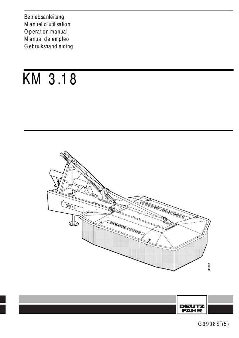
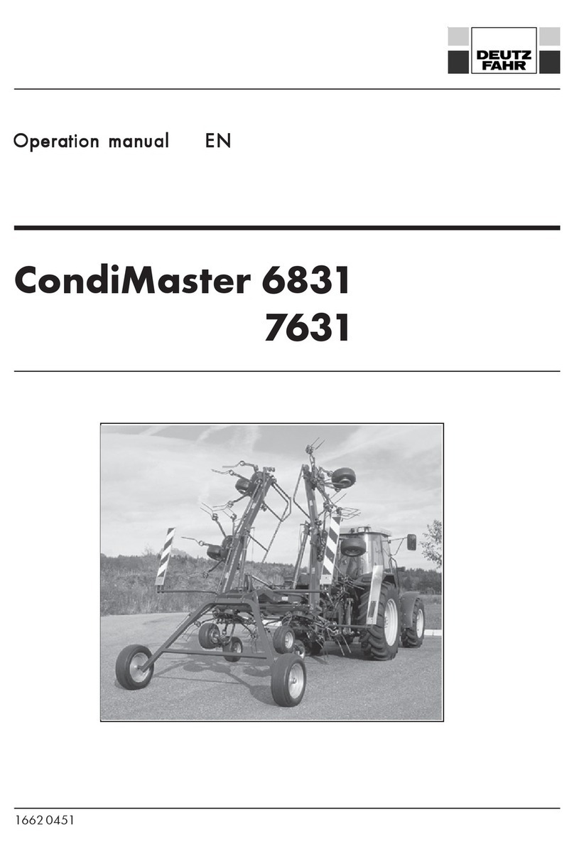
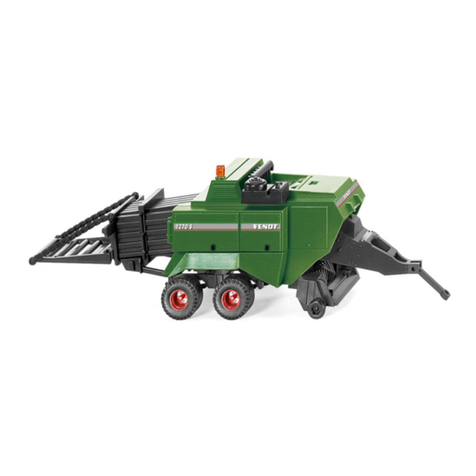
DEUTZ-FAHR MP135 R User manual

1665 2807.
MP135 R / MP135-OC23
Operation manual EN
en/05_2006


1
EN
16652807_en 05/2006
EC Declaration of ConformityEC Declaration of Conformity
EC Declaration of ConformityEC Declaration of Conformity
EC Declaration of Conformity
as defined by the EC directives
- Machines 89/392/EEC amended by 91/368/EEC and 93/44/EEC, Appendix II
and 93/68/EEC
The machine
product : round baler
type : MP 135 R / MP135 OC23
: RF135 R / RF 135 OC23
identity no. : 6830
serial no. : 6830 / 2501
year of construction : 2002
was solely developed, designed and manufactured, in accordance with the aforementioned EC directives,
by
Kverneland Group Gottmadingen GmbH & Co. KG
Hauptstraße 99
78244 Gottmadingen
Germany.
The following harmonised norms were applied:
- DIN EN 292/1 and EN 292/2, safety of machines, equipment and systems
- DIN EN 294, safety clearances to danger areas
- DIN EN 982, safety requirements of fluid technology systems and components
- prEN 704 (January 94) safety of agricultural machines - balers
- prEN ISO 14982:1996, electromagnetic compatibility of agricultural and forestry machines
Complete technical documentation is available.
The machine´s operating instructions are available
- in the original version : German
- in the languages : English, French, Dutch, Spanish, Italian, Swedish, Danish
Gottmadingen,30.05.2006
Casper Böhme
General Manager

2
EN
16652807_en 05 /2006

3
EN
16652807_en 05/2006
ForewordForeword
ForewordForeword
Foreword
Dear Customer,
We would like to thank you for the trust you are showing in our company in purchasing this Kverneland
fixed chamber round baler.
The following operating instructions provide detailed information on starting up and maintaining your
new round baler. They also contain safety instructions to ensure risk-free operation. In addition to the
equipment and variants that can be supplied, the operating instructions describe all additional equipment
not contained in the usual supply schedule. With these operating instructions, we aim to help you get the
most out of your Kverneland round baler.
The machine´s performance depends to a large extent on it being properly used and carefully maintained.
For this reason, the operating instructions should be read through with care before starting up for the first
time and should be kept to hand thereafter. By doing this, you will prevent accidents, have the
manufacturer´s guarantee, and always have a reliable machine that is ready for use.
All information and illustrations in these operating instructions are state-of-the-art at the point in time of
publication. Kverneland constantly strives to improve its products. It reserves the right to make all changes
and improvements that it considers to be necessary. This does not, however, oblige the company to
later modify machines supplied.
If, after reading the operating instructions, you should have further questions, please contact your retailer.
We hope you have a good harvest using your round baler!
Please read and take note of operating instructions and safety regulations prior to start-up.
Kverneland Group Gottmadingen GmbH & Co KG
Hauptstraße 99
78244 Gottmadingen
Germany
Tel.: 07311-788-0
Fill in your machine details here:
Machine type :....................................................................................
Serial number :....................................................................................
Initial start-up on :....................................................................................

4
EN
16652807_en 05 /2006
Table of contents
1 Safety.............................................................................. 7
1.1 Your personal safety................................................................................................... 7
1.2 Safety instructions in this manual .............................................................................. 7
1.3 Type plate..................................................................................................................... 8
1.4 Intended use.................................................................................................................8
1.5 Liability .......................................................................................................................... 8
1.6 Safety stickers and warning signs ............................................................................ 9
1.7 Authorised users ....................................................................................................... 13
1.8 General safety and accident prevention regulations ......................................... 13
1.8.1 General ............................................................................................... 13
1.8.2 Attached devices................................................................................ 14
1.8.3 Power take-off operation .................................................................. 15
1.8.4 Hydraulic system ............................................................................... 16
1.8.5 Tyres and brakes ............................................................................... 16
1.9 Safety when not in use and in storage ................................................................. 17
1.10Maintenance ............................................................................................................. 17
1.11Safety instructions for round balers....................................................................... 18
2 Technical data ................................................................ 19
2.1 General...................................................................................................................... 19
2.2 Measuring noise....................................................................................................... 20
3 General description ....................................................... 21
3.1 How the round baler functions .............................................................................. 21
3.2 Important components of the round baler............................................................ 22
4 Installation and adjustments........................................... 23
4.1 Tractor equipment necessary ................................................................................. 23
4.2. Mounting the "Autoform" ........................................................................................ 23
4.3 Adapting the drawbar............................................................................................. 24
4.4 Universal drive shaft, coupling ............................................................................... 25
4.5 Set baling pressure .................................................................................................. 26
4.6 Setting pick-up ........................................................................................................... 27
4.6.1 Setting pick-up height .................................................................................... 27
4.6.2 Setting pick-up unload .................................................................................. 27
4.6.3 Set pick-up baffle plate ................................................................................. 28
4.6.4 Pick-up overload protection feature............................................................ 28
4.7 Setting scrapers ........................................................................................................ 28
4.8 Shearing screws roller drive................................................................................... 28

5
EN
16652807_en 05/2006
5 Operation ......................................................................29
5.1 "Autoform" operation and control unit .................................................................. 29
5.2 Pick-up ........................................................................................................................ 35
5.3 ‘Opticut’ cutting system ........................................................................................... 36
5.3.1 General ............................................................................................... 36
5.3.1.1 Changing the blades .......................................................... 37
5.3.1.2 Adjusting the cutting angle ................................................ 38
5.3.2 OptiCut 23 ......................................................................................... 39
5.3.2.1 General................................................................................. 39
5.3.2.2 MP/RF 135 OC23 „Autoform“ ....................................... 40
5.3.2.3 Variable knife engagement in groups ............................. 40
5.4 Binding ....................................................................................................................... 41
5.4.1 General ............................................................................................... 41
5.4.2 Twine binding ..................................................................................... 42
5.4.3 Net wrapping..................................................................................... 43
5.5 Tailgate ...................................................................................................................... 45
5.6 Reversing mechanism .............................................................................................. 46
5.7 Hitching to the tractor and road travel ................................................................. 47
5.8 Operation in the field .............................................................................................. 47
5.9 Storing the Round Baler .......................................................................................... 49
5.10Winter storage .......................................................................................................... 49
6 Service and maintenance ............................................... 50
6.1 Re-tightening screws................................................................................................. 50
6.2 Checking wheels ...................................................................................................... 50
6.3 Central chain lubrication device ............................................................................ 51
6.4 Chain tightener ......................................................................................................... 51
6.5 Lubrication ................................................................................................................. 52
7 Accessories .................................................................... 53
7.1 Cutting system ........................................................................................................... 53
7.2 Filler plates ................................................................................................................53
7.3 Bale ramp .................................................................................................................. 53
7.3.1 Sensor for bale ejection.................................................................... 54
7.4 Additional twine box ............................................................................................... 54
7.5 Extension cable for "Autoform" .............................................................................. 54
7.6 Hydraulic oil filter..................................................................................................... 54
8 Fault finding................................................................... 55
A Appendix ...................................................................... 57
A.1 Torque values for international metric thread joints............................................ 57
A.2 Hydraulic scheme..................................................................................................... 58

6
EN
16652807_en 05 /2006
1 Safety
1.1 Your personal safety
The retailer will have explained to you about operation and maintenance when handing over the
machine. Read these operating instructions before using the machine for the first time and be sure to
note the safety instructions. Areas of particular importance are marked with a pictograph.
You will find this sign beside all important safety instructions in these operating
instructions. Take particular note of these and take extra care when carrying out the
operations to which they apply.
The round baler is equipped with protective equipment and its safety and the accident protection it
provides have been checked by the Landwirtschaftliche Berufsgenossenschaft [Agricultural Professional
Association]. However, in the case of maloperation or misuse, a danger is posed to the following:
zthe life and limbs of operators, third parties and animals near the machine,
zthe machine and other material assets belonging to the operator and third parties,
zthe efficient operation of the machine.
All persons concerned with the mounting, start-up, operation and maintenance of the machine must
carefully read and take note of the following instructions.
AfAf
AfAf
Aftt
tt
ter all, it is yer all, it is y
er all, it is yer all, it is y
er all, it is your safour saf
our safour saf
our safee
ee
ety tty t
ty tty t
ty that is at issue.hat is at issue.
hat is at issue.hat is at issue.
hat is at issue.
1.2 Safety instructions in this manual
How safety instructions are denoted:
Warning !
This word denotes danger to life or limb. If you see this word in the operating instructions,
please take all necessary safety precautions.
Caution !
This word indicates the risk of material damage as well as financial detriment and
disadvantage under criminal law (e.g. loss of guarantee rights, liability cases etc.).
Note:
This indicates instructions, application tips and practical information.

7
EN
16652807_en 05/2006
1.4 Intended use
The round baler is exclusively constructed for ordinary use in agricultural work and intended for and
suited to gathering mown crops lying in swaths on the ground, compressing this into round bales and
binding it with plastic twine or wrapping it with netting.
It is not intended for any other use. The manufacturer shall not be liable for damage resulting therefrom.
The user shall bear all responsibility.
Intended use also comprises adhering to the operating, maintenance and servicing directions prescribed
by the manufacturer. The machine may only be used, maintained and repaired by persons who are
familiar with the work and who have been informed of the dangers.
The relevant accident prevention regulations and other generally recognised regulations concerning
safety, industrial medicine and road traffic are to be observed.
Caution !
Unauthorised changes to the machine remove all liability on the manufacturer´s part for
damage arising therefrom.
1.5 Liability
All persons who work on and with this machine must read and note these operating instructions.
Furthermore, this machine may only be deployed for its intended use (see Section 1.4).
1. Work on this machine must be carried out in accordance with the instructions contained in the
current documentation.
This documentation can be made up of the following:
zmounting instructions
zoperating instructions
zsupplementary sheets
The identification plate with machine type and machine
number is located on the right hand side at the drawbar
linkage point.
Note:
Enter the data on the type plate into the
box provided for this purpose on the se-
cond page.
1.3 Type plate

8
EN
16652807_en 05 /2006
2. The following rules and regulations must be observed:
zthe locally applicable, relevant accident prevention regulations,
zthe recognised road traffic, safety and industrial medicine regulations,
zthe functional limits and safety regulations listed in the technical instructions.
3. Only suitable and perfectly functioning tools and equipment may be used in carrying out work on
the machine.
4. Only parts (replacement parts, additional equipment, lubricants etc.) may be used that at least
correspond to the requirements laid down by the machine manufacturer, and these parts must be
used in accordance with the regulations (including the starting torques mentioned).
A part corresponds to requirements when it is an original part or if it has been expressly approved
by the machine manufacturer.
5. Unauthorised changes to the machine remove all liability from the manufacturer for damage arising
therefrom.
Caution !
Any person not observing the above regulations shall be deemed to be acting in a grossly
negligent manner. The manufacturer shall bear no liability for damages arising therefrom.
The risk shall be borne entirely by the user.
1.6 Safety stickers and warning signs
Caution !
Real safety means being familiar with all safety stickers. This concerns the type and place of
danger and, in particular, the safety measures to be taken. Remain constantly vigilant and
be aware of the dangers.
Warning signs are provided on this machine (safety stickers). The stickers together with their explanations
are listed in the following and shown on the overall diagram:

9
EN
16652807_en 05/2006
1. Before putting the machine into operation, read
and understand the operator’s manual and the
safety precautions and follow all instructions given.
2. Before performing any service and repair work,
stop the engine and remove the ignition key.
3. Never open or remove protective devices when
the engine is running.
4. Close all protective devices before putting the
machine into operation.
5. During operation stand clear of the danger area
of the tailgate.
6. During operation stand clear of the danger area.

10
EN
16652807_en 05 /2006
7. Stand clear of the raised tailgate if same is not
locked against lowering.
8. Keep hands clear of the pick-up area when the
tractor engine is running and the pto shaft is
connected.
9. Secure the machine by wheel chocks to ensure
it cannot move away when uncoupled or stored.
10.Before performing any work under the tailgate or
in the bale chamber, close the hydraulic shut-off
tap to lock the tailgate.
(the hydraulic stop-cock is on the right at the front
on the machine, behind the hydraulic block).
11.Never exceed the prescribed pto speed
nmax = 540 rpm.

11
EN
16652807_en 05/2006
12.

12
EN
16652807_en 05 /2006
1.7 Authorised users
Youths under 16 years of age may not operate the round baler.
The owner of the machine must make the operating instructions available to the user and ensure that the
latter has read and understood same. Only then may the user operate the machine.
The delegation of responsibility for various machine duties must be clearly established and adhered to.
There must be no doubt regarding the user´s competence as this could put the user at risk.
The owner must ensure that only authorised persons work on the machine. He is responsible for third
parties for the area in which the round baler is being used.
1.8 General safety and accident prevention regulations
Basic rule:Basic rule:
Basic rule:Basic rule:
Basic rule:
Check that the device and tractor are road worthy and operationally safe before each start-up. Note
the generally applicable safety and accident prevention regulations as well as the instructions in these
operating instructions.
1.8.1 General
1. The warning and notice signs posted provide important information for risk-free operation.
Please note these instructions for your own safety.
2. Make yourself familiar with all equipment, operating elements and their functions prior to commencing
work. Ensure that all protective devices are properly attached.
3. The user´s clothing must fit closely. Do not wear baggy clothes. Wear sturdy shoes.
4. Keep the machine clean. Be aware of the risk of fire.
5. When using public thoroughfares, please observe the following:
zthe statutory road traffic regulations,
zthe permissible axle loads and total weights,
zthe permissible transport dimensions.
zNever leave the operator´s platform while travelling.
6. The equipment must be in the condition prescribed for road transport and be locked according to
the manufacturer´s instructions.
7. Check and secure transport equipment and the lighting, warning and protective equipment.

13
EN
16652807_en 05/2006
8. Operating devices (ropes, chains and linkage) of remote controlled equipment must be installed in
such a way that they can not trigger unintentional movements in any transport and working position.
9. Couple equipment according to regulations, and attach and secure to the prescribed devices.
Particular care should be taken when coupling and decoupling equipment to or from the tractor.
10.When attaching or detaching, bring the support devices into the position necessary. Be conscious
of its stability.
11.Never run the engine in an enclosed area.
12.Check the surrounding area (children) before driving away and starting up. Ensure that you have
adequate visibility.
13.Passengers may not be carried on the equipment while on a transport journey. No work may be
carried out on the device while in operation.
14.Always adjust travelling speed to suit weather and terrain conditions. Avoid taking sudden curves
on inclines and declines and transverse travel on an incline.
15.Attached equipment influences road performance as well as steering and braking. Ensure that you
can steer and brake adequately.
16.When taking curves, bear in mind the overhang width and the centrifugal mass of the device.
17.Only operate the device if all protective equipment is in place and in protection position.
18.It is forbidden to remain in the working and danger area.
19.Do not remain in the rotating and swinging range of the device.
20.There are crushing and cutting areas at power-driven parts (e.g. hydraulic parts).
21.Secure equipment before leaving the tractor. Lower the attached implement fully. Switch off the
engine and remove the ignition key.
22.No one may remain in the area between the tractor and device if the vehicle is not secured against
rolling away by a wheel chock.
23.Note the permissible axle load and total weight as well as the permissible transport dimensions.
1.8.2 Attached devices
1. Secure the device so that it cannot roll away. The wheel blocks are located behin the hinged door
on the right hand side of the machine.
2. Take note of the maximum permissible support load of the drawbar coupling, the pending attachment
or hitch.
3. Ensure that the drawbar trailer has sufficient mobility at the point of attachment.

14
EN
16652807_en 05 /2006
1.8.3 Power take-off operation
Applies only to PTO driven equipment.
1. Use only universal drive shafts prescribed by the manufacturer.
Ensure that the universal drive shaft is correctly mounted and secured.
The protective tube and guard cone of the universal drive shaft must be properly attached and be in
perfect condition.
Protect guard cone of universal drive shaft from being turned by attaching the chain.
Ensure that the prescribed pipe overlaps are in transport and working position for the universal
drive shafts.
2. No one may enter the area of the turning universal drive shaft when working with the universal
drive shaft.
3. When using universal drive shafts with an excess load or free-running couplings, overload or free-
running couplings are to be attached to the equipment.
4. The universal drive shaft is only to be attached or detached when the PTO shaft and engine have
been switched off and the ignition key has been removed.
Place the uncoupled universal drive shaft on the appropriate mount or hang in the chain provided.
After detaching the universal drive shaft, place the protective cover on the PTO shaft end.
5. The PTO guard must be properly attached and be in perfect condition.
Before switching on the PTO shaft, ensure that the rpm selected and rotational direction of the
tractor PTO shaft corresponds with the permissible rpm and rotational direction of the device.
Before switching on the PTO shaft, ensure that no one is in the machine´s danger area.
6. Never switch the PTO shaft on while the machine is switched off.
7. Always switch off the PTO shaft if the angles of operation are too large or if you do not need it.
8. Only clean, lubricate or set the PTO driven equipment or universal drive shaft when the PTO shaft
and engine are switched off and the ignition key has been removed.
9. Any damage is to be repaired before using the machine.

15
EN
16652807_en 05/2006
1.8.4 Hydraulic system
1. Warning: The hydraulic system is under high pressure.
2. Check the hydraulic hose pipes regularly and replace them when they are damaged or become
old. The replacement hose pipes must correspond to the technical requirements of the equipment
manufacturer.
3. Lower equipment and units before commencing work on the hydraulic system. First depressurize the
system and then switch off the engine (Pressure gauge display, 0 bar).
4. Use appropriate aids when searching for leaks. Be aware of the risk of injury.
5. The prescribed connection of hydraulic hoses is to observed when connecting hydraulic cylinders.
When connecting the hydraulic hoses to the tractor hydraulic system, ensure that the hydraulic
system is depressurized both at the tractor and at the equipment. Only connect up compatible
hydraulic fittings!
6. Mark the coupling sleeves and plugs at hydraulic function connections between the tractor and
equipment to avoid misconnections. If the connections are mixed up, the functions of the components
are reversed (e.g. raising, lowering). Be aware of the risk of accidents.
zred = open,
zyellow = close,
znot marked = pick up
7. Liquids escaping under high pressure (hydraulic oil) can penetrate the skin and cause serious injury.
In the case of injury, medical advice is to be sought immediately. Risk of infection.
8. After closing the tailgate and then allowing pressure to build up (control by the pressure gauge on
the hydraulic block), the tractor control valve is to be returned to the neutral position.
1.8.5 Tyres and brakes
1. When carrying out work on the tyres, ensure that the machine is safely parked and secured against
rolling away. Use the wheel chocks.
2. The mounting of tyres and wheels calls for a sufficient level of knowledge and mounting tools
conforming to specifications.
3. Repair work on and the mounting of tyres and wheels may only be carried out by skilled persons
using tools suited to the purpose.
4. Check air pressure regularly. Adhere to prescribed air pressure.
5. The wheel nuts are to be tightened after the first 10 operating hours. The torque moment is 325 Nm
(M18 x 1.5).
6. Check that the brakes are in proper working order before each journey.
7. The brake system is to be checked on a regular basis.
8. Adjustment and repair work on the brake system may only be carried out by a specialist workshop
or a recognised brake service.

16
EN
16652807_en 05 /2006
1.9 Safety when not in use and in storage
1. Store the device in a safe place.
2. Never allow children to play on or around the device.
3. Never couple or decouple the device on anything but firm, dry and level ground. This reduces the
risk of overturning or sinking into soft ground or mud.
4. Lay down the decoupled universal drive shaft on the mount provided.
1.10 Maintenance
Direction signs (‘to the right’, ‘to the left’, ‘to the front’, ‘to the back’) apply to the direction of travel.
The direction of rotation is defined as follows:
zdirection of rotation right = clockwise,
zdirection of rotation left = anti-clockwise,
zrotation about a perpendicular axis, viewed from top to bottom,
zrotation about a horizontal axis, at right angles to the direction of travel, viewed from left to right,
zrotation of bolts, nuts and similar, always viewed from the operating side.
1. Repair, maintenance and cleaning work and the elimination of malfunctions may only ever be
carried out when the drive mechanism is switched off and the engine is at a standstill. Remove
ignition key.
2. Check nuts and bolts regularly to ensure that they are tight and re-tighten if necessary. Keep to the
torques given. (See Appendix A.1 for torques for bolt connections).
3. When carrying out maintenance work on the raised device/unit, always secure with suitable supports.
4. When interchanging work tools, use suitable tools and wear gloves.
5. Dispose of oils, grease and filters properly.
6. Always disconnect the current supply before carrying out work on the electrical system.
7. If protective equipment is subject to wear and tear, it is to be checked regularly and replaced in
good time.
8. Disconnect cable to generator and battery when carrying out electrical welding work on the tractor
and attached devices.

17
EN
16652807_en 05/2006
1.11 Safety instructions for round balers
1. General safety instructions are contained in this manual as well as in the German agricultural
association health and safety regulations VSG 1.1 (01.01.2001).
2. The round baler is to be attached to the tractor before start-up. (Risk of overturning when the tailgate
is opened).
3. Never operate the round baler without a protective device.
4. Protect guard tube of universal drive shaft and protecting pot from being turned. Fit the safety chain!
5. Wait for all moving parts to come to a standstill before carrying out any work on the press.
6. Blockages are only to be removed and malfunctions are only to be eliminated when the PTO shaft
is switched off and the engine is at a standstill. Remove the ignition key. There is a risk of getting
caught in moving parts.
7. Never try to introduce the crop by machine or to remove blockages as long as the press is in
operation.
8. Only insert binding material (twine and netting) when the tractor engine is switched off and the
ignition key has been removed. There is a risk of getting caught in moving parts.
9. Only thread twine and netting and eliminate malfunctions when the tractor engine is switched off
and the ignition key has been removed.
10.When moving the support device, beware of crushing and cutting areas.
11.No one may be in front of the pick-up while the press is running. There is a risk of getting caught in
moving parts.
12.No one may be behind the machine while bales are being ejected.
13.While in operation, keep at a sufficient safety distance from the feed elements such as the pick-up,
intake auger etc.: due to their function, the feed elements cannot be fully covered.
14.Only eliminate malfunctions of feed elements such as the pick-up, intake auger, conveying roller
etc. when the tractor engine has been switched off and the ignition key has been removed.
15.The permissible speed limit is to observed when transporting on roads.
16.Repairs to prestressed energy accumulators (springs etc.) call for sufficient knowledge and mounting
tools that conform to specifications and may only be carried out in specialist workshops.
Hydraulic accumulators may not be repaired!
17.To avoid the risk of fire, it is recommended to carry a 12 kg fire extinguisher.
18.When working on hilly terrain, lay round bales face down on the slope incline so that they can not
roll away.
19.Do not try to stop a round bale rolling down a slope. Be aware of the risk of injury.
20.Take particular care when opening and closing the tailgate. Persons may not enter the swinging
range of the gate.
21.Before entering the bale chamber, the tailgate supports must be brought into safety position and the
shut-off tap in the hydraulic supply tube must be shut.
22.Whenever work is being carried out on or around the beating arm/net wrapping, the cutting device
must not be live.

18
EN
16652807_en 05 /2006
2 Technical data
2.1 General
-adnatS dr noitpO
thgiew,snoisnemiD
mm/htgnel0714
mm/htdiw0742
mm/thgieh0122
gk/thgiew)tnempiuqedradnats(0552
gni
thgil/gnitarepO
ehtnostinulortnocyrasseceN edisrotcart tinulortnocgnitca-elbuod1/elgnis1
"MROFOTUA"xoblor
tnocelbachtiw,0869NIDnip-eerht tniopgnitalosi x
m5,1noisnetxeelbacx
:gnithgil-ylppustnerruC
htiwecnadroccani
;nip-neves OZVTS ytefaSelciheVrotoMlaredeF( )sdradnatS
x
gnihctiH
hctihgnirmm04x
elbatatorhctihgnirmm04x
dexif:ey
ehctihmm25x
hctihmm33x
msinahcemevirD
raeglartnecnim045
1-
EWW/tfahsevird.vinumN0081hctulcniphtiw
rebmahcgnillornevirdlellaraptrapraer/tnorf
lasreverrotoRlacinahcem
p
UkciP
mmni/htdiwgnikrow0012x
sworenitforebmuN5x
tfiLciluardyhx
sgnirpsnoitasnepmoCsyaw4elbatsujdax
citamuenp-leehw
releeFsyaw6x2elbatsujdax
etalpelffaBx
erutaefnoitcetorpdaolrevO139NID8.854x8Mtlobraehsx
metsysgnittuctuCitpO x
stniopgnittucforebmuN41x
mmni-ecnatsidefinK07x
setalpgnillifedalB41x
This manual suits for next models
1
Table of contents
Other DEUTZ-FAHR Farm Equipment manuals
Popular Farm Equipment manuals by other brands

Sulky Burel
Sulky Burel DPX Expert Series manual

360 YIELD CENTER
360 YIELD CENTER 360 Series installation instructions

Quattro
Quattro Titanium EGO400 Installation guide and user information

IBEX
IBEX TS106 Use and maintenance manual

Green Frog Designs
Green Frog Designs Duck & Goose House Large How to use and care for

Haybuster
Haybuster 2100 BALEBUSTER Operating instructions and parts manual
