DEUTZ-FAHR SwatMaster 7131 EVO User manual

SwatMaster 7131 EVO
Operating manual
Edition 11/2006
Date printed 12.2006
Language EN
Implement number 5001 -
Type / series 6962/16
Document number VF16643769
All manuals and user guides at all-guides.com

Identification of the implement
Your dealer requires some information about your implement in order to be able to help you as quickly as
possible.
Please enter the information here.
Designation
Working width
Weight
Implement
number
Accessories
Address of
the supplier
Manufacturer's
address
Kverneland Group Gottmadingen N. V. of Germany owns the copyright and right of exploitation. Reproduction, transfer to other media, translation
or the use of extracts or parts of this manual without the explicit permission of Kverneland, is not permitted. All rights reserved. The contents of
this operating manual are subject to change without notice. The right to technical revision is reserved.
SwatMaster 7131 EVO
Kverneland Group Gottmadingen N.V.
Industriepark 312
78244 Gottmadingen
Germany
Tel.: +49 7731 788 - 0
7.10 metres
All manuals and user guides at all-guides.com

Table of contents
3
Tabl e of conten ts
Preliminary information ..................................4
Target group for this operating manual 4
Meaning of the symbols 4
Safety................................................................5
For your safety 5
Who is allowed to operate the implement 6
Coupling 6
Driving on the road 8
Initial operation 9
Uncoupling the implement 10
Care and Maintenance 10
Further regulations 11
Familiarise yourself with the device............12
Area of application of the implement 12
Features of the implement 12
Component designations 13
Specifications 14
Delivery and assembly..................................17
Checking the scope of supply 17
Coupling the implement................................18
General 18
Coupling to the lift link drawbar 18
Coupling to the pending attachment 19
Coupling the cardan shaft 20
Wheel wedges 20
Rip chain for USA and Canada 20
Connections 21
Preparing for operation.................................23
Safety 23
Working depth 24
Stabiliser [+] 25
Raking wheel pitch 26
Tine anti-loss device [+] 26
Driving on the road........................................27
Safety 27
Prior to travel on public roads 27
Road transport 32
Preparations on the field ..............................33
Safety 33
General 33
Swath deposit 34
Attaching the tine support 38
Pulling out the guard 38
Swath former, rear 39
Swath former, front [+] 41
Operation........................................................42
Safety 42
General 43
3-way ball valve 43
Swathing 44
Cleaning and care ......................................... 46
Safety 46
Cleaning 46
Care 46
Parking and storage...................................... 47
Safely setting down the implement 47
General 47
After the end of the season 47
Maintenance................................................... 48
For your safety 48
General 50
Screw connections 52
Lubrication points for grease lubrication 53
Lubricating the cardan shafts 54
Adapting the cardan shaft 55
Filling volumes 56
Tyres 56
Hydraulic 56
Accessory equipment ................................... 57
Tine anti-loss device 57
Tandem axles 57
Roller feelers 57
Lift link drawbar 57
Front swath former 58
Height adjustable sustainer 58
Fault................................................................ 59
Circuit diagrams............................................ 60
Hydraulic circuit diagram 60
Lighting circuit diagram 61
Disposal ......................................................... 62
EC Conformity Declaration........................... 63
in conformity with the
EC Directive 98/37/EC 63
Index ............................................................... 64
All manuals and user guides at all-guides.com
4
Preliminary information
Prel imi nary informat ion
Target group for
this operating ma-
nual
This operating manual is directed at trained farmers and individuals
who are otherwise qualified to perform agricultural activities and who
have received instruction on the handling of this implement.
For your safety
Familiarise yourself with the contents of this operating manual before
assembly or initial operation of the implement. In this way, perfor-
mance and work safety are optimised.
The employer should:
All personnel are to be regularly instructed on the use of the imple-
ment, at least once annually, in accordance with the regulations of
section 1 of the trade's mutual indemnity association. Untrained or un-
authorised persons are not allowed to use this implement.
Training
Your dealer will provide instruction on operation and care of the imple-
ment.
Meaning of the
symbols
In order to make this manual clear and easy to read, we have used va-
rious symbols. They are explained below:
•
A dot accompanies each item in a list
> A triangle indicates operating functions which must be performed
→
An arrow indicates a cross-reference to other sections of this ma-
nual
[+] A plus sign indicates an add-on item of equipment, which is not
included in the standard version.
N
OTE
The term, “Note” indicates tips and notes on operation.
The screwdriver indicates tips during assembly or adjustments.
The warning triangle indicates important safety instructions. Failure
to observe these safety instructions can result in:
•
Coarse defects in the operability of the implement
•
Damage to the implement
•
Personal injury or accidents.
0
A star indicates examples that assist understanding of the instruc-
tions.
All manuals and user guides at all-guides.com
Safety
5
Safety
For your safety
This chapter contains general safety instructions. Each chapter of the
operating manual contains additional specific safety instructions
which are not described here. Observe the safety instructions
•
in the interest of your own safety,
•
in the interest of the safety of others, and
•
to ensure the safety of the implement.
Numerous risks can result from handling agricultural implements in
the wrong way. Therefore, always work with special care and never
under pressure.
The employer should:
At regular intervals inform those who work with the implement about
these safety instructions and the
statutory regulations.
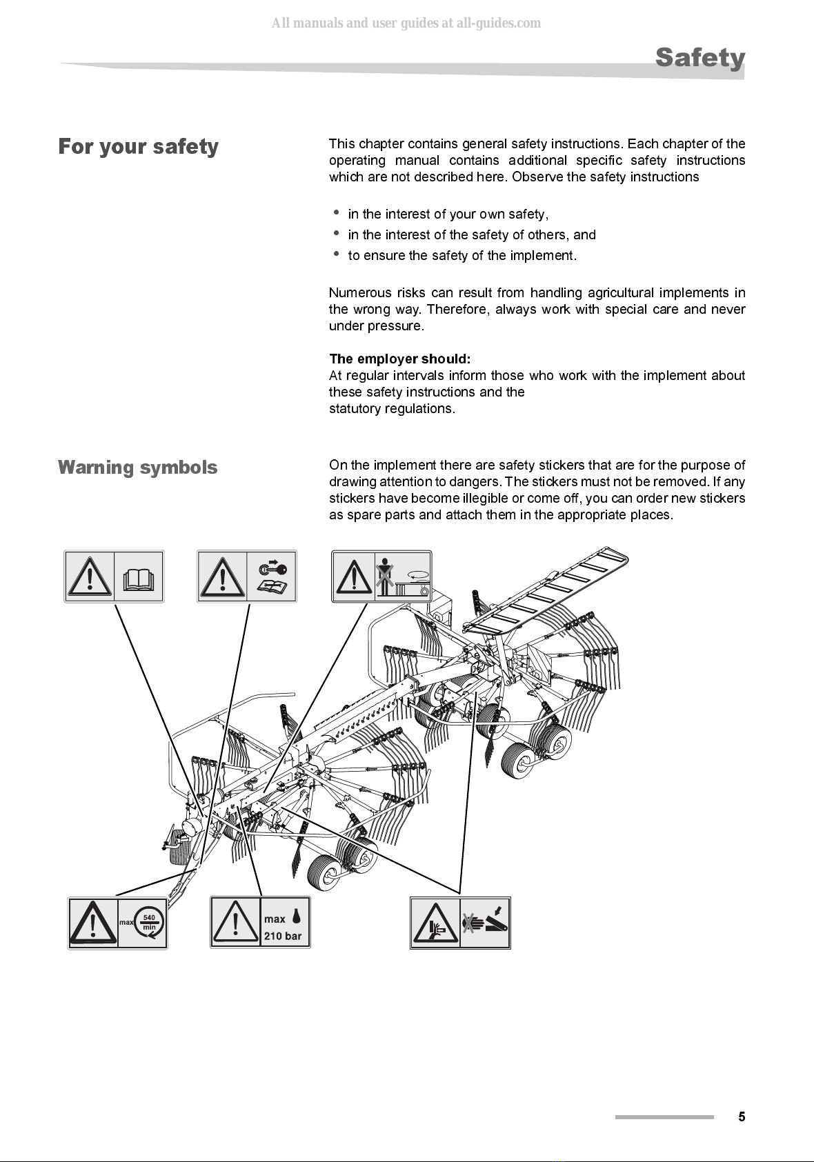
Warning symbols
On the implement there are safety stickers that are for the purpose of
drawing attention to dangers. The stickers must not be removed. If any
stickers have become illegible or come off, you can order new stickers
as spare parts and attach them in the appropriate places.
All manuals and user guides at all-guides.com

6
Safety
Meaning of warning sym-
bols
Read the operating manual
Read and observe the operating manual and the safety regulations
prior to initial operation!
Switch off the engine
Perform all maintenance, repair and adjusting work only when the im-
plement is at a standstill.
Keep your distance
Keep your distance from the rotating raking wheel. When the wheel ra-
ke is in operation nobody is allowed in the immediate vicinity of the im-
plement!
Maximum cardan shaft speed 540 rpm
The prescribed maximum cardan shaft speed of 540 rpm must not be
exceeded.
Risk of crushing
Never reach into the zone where there is a risk of getting crushed as
long as any parts there are able to move.
Maximum hydraulic pressure 210 bar
The hydraulic pressure of the tractor on the implement's hydraulic sy-
stem must not exceed 210 bar.
Who is allowed to
operate the imple-
ment
Only qualified personnel
Only qualified persons who have been informed of the dangers asso-
ciated with handling the implement are permitted to operate, service
or repair the implement. As a rule, such persons are trained and ex-
perienced in agricultural work or have been thoroughly trained in a si-
milar fashion.
Coupling
Increased risk of injury
When coupling the implement to the tractor, there is an increased risk
of injury. Therefore:
•
secure the tractor against rolling away, shut off the engine and take
out the ignition key
•
never stand between the tractor and the implement during coupling
•
when hitching onto the lift link drawbar fix the lower link laterally
and lock the three-point power lift against lifting and lowering.
•
lock the cardan shaft securely to the PTO shaft end of the tractor
and implement
If this is not complied with, the consequence can be damage to the im-
plement and even life-threatening injuries.
All manuals and user guides at all-guides.com
Safety
7
Cardan shaft
Use only the cardan shafts prescribed by the manufacturer and read
the attached operating manual attentively. Adapt the length of the car-
dan shaft as required. The wrong cardan shaft lengths can cause da-
mage to the implement and injuries to personnel.
Check and fix the cardan shaft guard
The rotating cardan shaft is protected by the cardan shaft guard. En-
sure that the guard is not damaged. Fix the cardan shaft guard by con-
necting the chains on the implement and tractor faces. Unguarded
cardan shafts can cause life-threatening injuries.
Maximum cardan shaft speed 540 rpm
The prescribed maximum cardan shaft speed of 540 rpm must not be
exceeded. Higher rpm's can cause damage to the implement.
Hydraulic connection at zero pressure only
Only connect hydraulic tubes to the tractor hydraulic system if the trac-
tor and implement hydraulic system is depressurised. A pressurised
hydraulic system can trigger unforeseeable movements on the imple-
ment.
High pressures in the hydraulic system
The hydraulic system is under high pressure. Regularly check all
pipes, hoses and bolted connections for leaks and externally visible
damage. Only use suitable agents when looking for leaks. Eliminate
damage immediately. Escaping fluid may result in injuries and fires.
Seek medical attention immediately if injuries occur.
Colour-coded hydraulic connections
To avoid operating errors, the plug sockets and plugs of the hydraulic
connections between the tractor and implement are colour coded.
Wrongly connected hydraulic hoses can trigger unforeseen move-
ments on the implement.
All manuals and user guides at all-guides.com

8
Safety
Driving on the road
Make sure that the condition of the implement conforms to traffic
regulations.
The implement must conform to current national traffic regulations if
you intend to drive it on public roads. This includes, for example:
•
Lights, warning equipment and guard devices are installed
•
Compliance with the permissible transport widths and weights, ax-
le loads, tyre loadbearing capacities, laden weights and national
speed restrictions
•
Compliance with the maximum permissible transport speed of
40 km/h.
If this is not complied with, the driver and keeper of the vehicle are lia-
ble.
Close the ball valve
Close the ball valve before driving on the road. If the ball valve is open
and there is an operating error, the implement can drop. This can cau-
se damage to the implement.
Check tyre pressure
Check tyre pressure regularly. The wrong tyre pressure will reduce the
service life of a tyre and can cause unstable driving properties and ac-
cidents.
Check the pin connection
The hitch pin must be in perfect condition, there must be no signs of
wear and it must be properly secured. Otherwise coupled implements
are able to detach themselves.
Check remote cord for the quick release coupling
Remote cords must hang loose and must not, when in their lowered
position, release the couplings of their own accord. Coupled imple-
ments can otherwise detach themselves independently from the trac-
tor's lower link arm.
No riding on the implement
Neither personnel nor objects are allowed to be transported on the im-
plement at any time. Riding on the implement is hazardous and strictly
prohibited.
Altered driving and braking performance
The driving and braking performance are altered when the implement
is attached to the tractor. Take the width and balancing weight of the
implement into consideration, especially on sharp bends. A driving
style which is not adapted to road conditions can cause accidents.
Adapting the speed
In the event of bad road conditions and excessive speed very high
forces can occur that subject the material of the tractor and of the im-
plement to high loads or to an overload. It is therefore important to ad-
just your speed to the road conditions. A driving style which not adap-
ted to road conditions can cause accidents.
All manuals and user guides at all-guides.com
Safety
9
Initial operation
The implement should not be put into operation for the first time
until the user has been trained to use it.
The implement must not be used for the first time until an instruction
lesson has been given by employees of the distribution associates,
company representatives or employees of the
manufacturer. If initial operation is performed without instruction, da-
mage to the implement can be caused by operating errors and acci-
dents can occur.
Ensure that the implement is in perfect working condition.
Do not operate the implement unless it is in perfect working condition.
Check all important components and replace any defective compon-
ents before starting the implement. Defect components can cause da-
mage to equipment and injury to persons.
Do not remove the protective equipment.
The guard devices must not be removed or by-passed. Check all
guard devices before starting the implement. Unguarded parts of the
implement can cause serious or fatal injuries.
No riding on the implement
Neither personnel nor objects are allowed to be transported on the im-
plement at any time. Riding on the implement is hazardous and strictly
prohibited.
Make sure the immediate vicinity is clear
Before starting, unfolding and commencing operation, check the sur-
rounding area of the implement. Make sure the operator has an ade-
quate view of the work area. Do not begin work until the immediate
vicinity is cleared of any persons or objects. Life-threatening injuries
can occur.
Retighten all nuts, bolts and screws
Nuts, bolts and screws should be checked at regular intervals and
tightened if necessary. Screws can work loose through the use of the
implement. The consequence can be damage to the implement and
accidents.
What to do in the event of a malfunction
In the event of a malfunction, shut down and secure the implement im-
mediately. The malfunction may be eliminated immediately, or your
dealer must be assigned the task. Continued operation of the imple-
ment can cause damage and accidents.
All manuals and user guides at all-guides.com
10
Safety
Uncoupling the im-
plement
Increased risk of injury
There is an increased risk of injury when uncoupling the implement
from the tractor. Therefore:
•
Secure the tractor against rolling away, switch off and take out the
ignition key
•
Never stand between the tractor and the implement during uncou-
pling.
•
Ensure that the implement is standing on a flat and stable surface
•
Ensure that the parking leg is securely locked
•
Set the cardan shaft down on the mounting provided
•
Secure the implement against rolling away (use wheel wedges)
•
Do not disconnect the hydraulic hoses until the hydraulic system is
unpressurised on both the tractor and implement faces
If this is not complied with, the consequence can be serious or fatal
injuries.
Care and Mainte-
nance
Follow the care and maintenance chart
Observe prescribed intervals for maintenance checks and inspections
specified in the operating manual. If these intervals are not complied
with, damage to the implement and accidents can be caused.
Only use OEM replacement parts (original equipment manufac-
turers).
Many components have special properties that are decisive for the
stability
and operability of the implement. Only spare and wear parts
supplied by the manufacturer have been tested and cleared. Using
other products may lead to malfunctions or reduce safety of operation.
The use of non-OEM replacement parts renders the manufacturer's
guarantee null and void and frees the manufacturer from all liability.
When performing care and maintenance work:
•
Switch off the cardan shaft drive
•
Depressurise the hydraulic system
•
Whenever possible, uncouple the tractor
•
Switch off the tractor and withdraw the ignition key
•
Make sure the implement is standing safely. Provide additional
supports as required
•
Do not use parts of the implement to climb onto it; use only secure
steps, ladders or other means of access
•
Secure the implement against rolling away (use wheel wedges)
Only if these regulations are complied with is safety ensured during
care and maintenance work.
Turn off the electrical supply
Prior to carrying out work on the electrical system, disconnect it from
the power supply. Equipment under electrical power can cause dama-
ge to equipment and injury to persons.
All manuals and user guides at all-guides.com

Safety
11
Replace hydraulic tubes
Hydraulic tubes can age without this being externally visible. We the-
refore recommend replacing the hydraulic hoses every six years. De-
fective hydraulic lines can lead to severe or fatal injuries.
Caution when cleaning with a high-pressure cleaner
The implement can be cleaned using either water or a steam jet. Cle-
an the bearings, plastic parts and hydraulic hoses using low pressure
only. Excessive pressure can damage these parts.
No corrosive washing additives
Do not use any corrosive washing additives for cleaning. The bright
metal surfaces can get damaged.
Prior to
carrying out
welding work
Before performing any electrical welding work on the uncoupled im-
plement, disconnect the tractor's battery and the alternator. This will
avoid damaging the electrical system.
Tighten the screw connections
Retighten any loosened screw connections after care and mainte-
nance work. Serious personal injuries and damage to property can be
caused by loose screw connections.
Further regulati-
ons
Observe the regulations
In addition to those listed above, please observe the following safety
instructions:
•
Accident-prevention regulations
•
Generally recognised safety regulations, occupational health re-
quirements and road traffic regulations
•
Instructions given in this operating manual
•
Regulations pertaining to operation, maintenance and repair.
All manuals and user guides at all-guides.com

12
Familiarise yourself with the device
Fam iliarise yourself with the de vice
Area of application
of the implement
The implement is a two-wheel rake, which is suitable only for the ra-
king together of mowed stalk-type vegetation (for example, hay or
straw). By hydraulic adjustment of the two raking wheels the crop can
be deposited in a swath or in two individual swaths.
Proper use
Any other use extending beyond this, for example, for silo distribution,
any form whatsoever of soil preparation, road sweeping or for the
transmission of power to other implements is not an intended use. The
manufacturer and dealer are not liable for damage caused by impro-
per use. Improper use is solely at the risk of the user.
Features of the im-
plement
Versatility - for a single swath or two individual swaths
This rake meets all the requirements of modern fodder heaping tech-
nology, no matter whether a 12.5 m wide double swath has to be pro-
vided for a high-output fodder harvesting implement or small swaths
for the hay harvest. The rake can be pulled by tractors of 30 kW or mo-
re by the pending attachment, hitch or lift link drawbar.
Extensive equipment
The implement is equipped with low-maintenance gearboxes and
11 rotating arms on the front and rear raking wheel. Excellent raking
quality is achieved thanks to the bent prongs. Each raking wheel can
be equipped optionally with tandem axles with 18“ wheels.
Together with the "TerraLink" support these ensure excellent following
of the ground contour.
Flexible due to the swivelling rear raking wheel
The facility for lateral outward slewing of the rear raking wheel to the
left or right offers many usage options.
All manuals and user guides at all-guides.com

Familiarise yourself with the device
13
Easy changeover from operating to transport position
The rake is easily changed over from operating to transport position.
Hydraulic cylinders lift the rake into transport position and the swath
former folds up hydraulically to maintain the transport width of less
than 3.0 m with the tine arms attached. If a smaller transport width is
required, the tine arms can be removed, fixed in parking position and
the guard can be pushed in.
50 centimetre lift-out height
For road transport and at headlands the implement can be quickly lif-
ted out by roughly 50 centimetres. For working, lower the wheel rakes
hydraulically from transport position back to working position.
Component desi-
gnations
Support arm
Drawbar Drawbar cylinder Axle support
Chassis cylinder
Cardan shaft
Articulated arm
Cross beam
Swath former
Pivoting cylinder
Raking wheel arm
Tine support
Tandem axle
Raking wheel gear
Slewing gear
All manuals and user guides at all-guides.com
14
Familiarise yourself with the device
Specifications
Dimensions
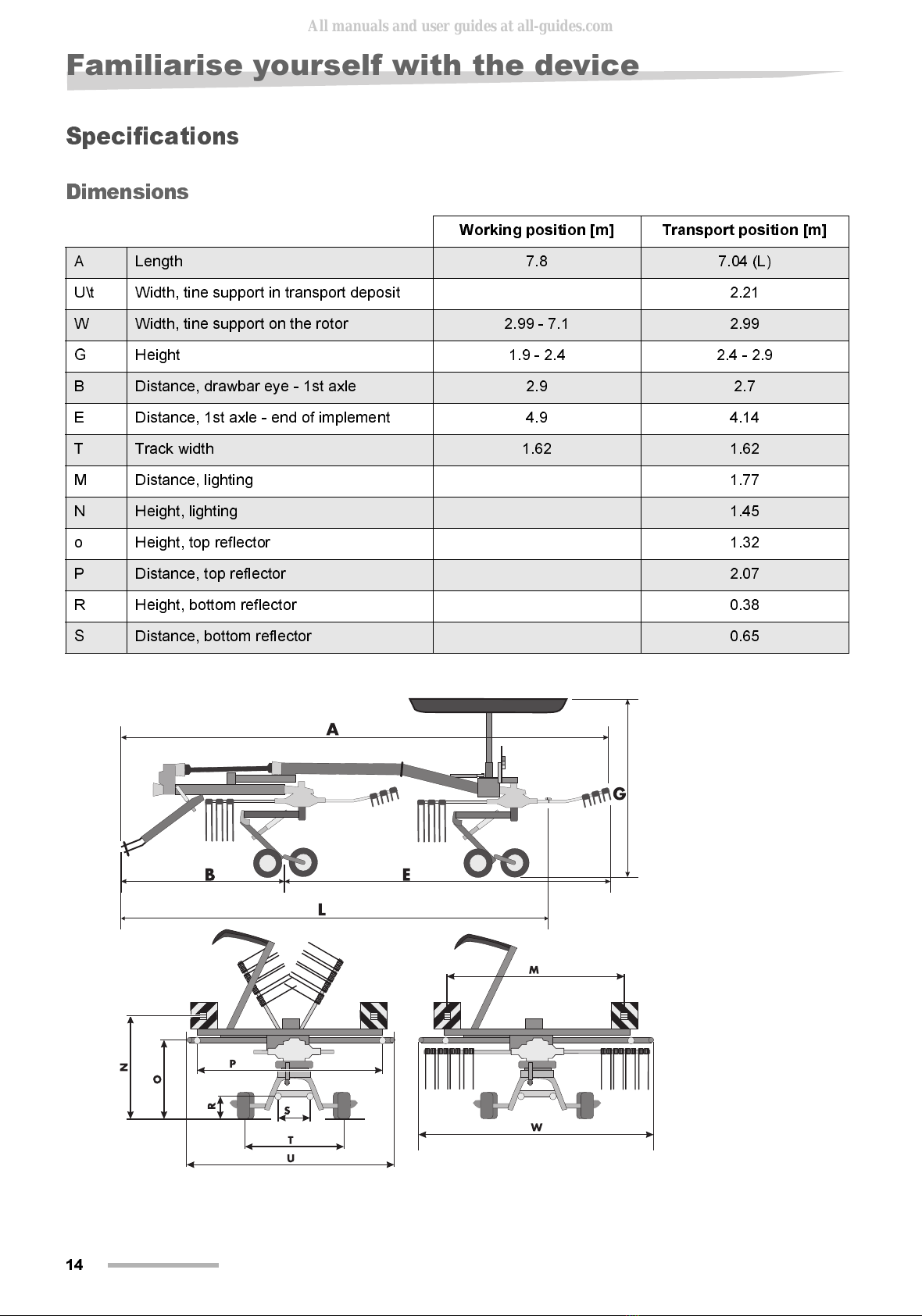
Working position [m] Transport position [m]
ALength 7.8 7.04 (L)
U\t Width, tine support in transport deposit 2.21
WWidth, tine support on the rotor 2.99 - 7.1 2.99
G Height 1.9 - 2.4 2.4 - 2.9
BDistance, drawbar eye - 1st axle 2.9 2.7
E Distance, 1st axle - end of implement 4.9 4.14
TTrack width 1.62 1.62
M Distance, lighting 1.77
NHeight, lighting 1.45
o Height, top reflector 1.32
PDistance, top reflector 2.07
R Height, bottom reflector 0.38
SDistance, bottom reflector 0.65
All manuals and user guides at all-guides.com

Familiarise yourself with the device
15
Weights
Tractor equipment
required
Operating position Transport position
Gross weight 1393 kg 1393 kg
Load supported on the stabiliser 150 kg 160 kg
Axle load of 1st axle 633 kg 663 kg
Axle load of 2nd axle 610 kg 570 kg
Output / connections
Minimum output of the tractor 30 kW
Lighting power supply 12 V, 7-pin plug socket ISO 1724
Hydraulic connections 1 x double acting / 1 x single acting
Hydraulic pressure 150 - 210 bar
Cardan shaft speed 540 rpm
Lift link drawbar Fixable in height and laterally
Pending attachment Standard
All manuals and user guides at all-guides.com

16
Familiarise yourself with the device
Equipment of the im-
plement
Swath deposit
Swath former for rear raking wheel Standard
Swath former for front raking wheel [+]
Raking wheels / raking wheel arms / tines
Number of raking wheels 2
Number of arms per raking wheel 11
Number of tines per raking wheel arm 4
Tine arms removable Standard
Raking wheel precision height adjustment Mechanical
Hydraulically liftable swath former Standard
Tine anti-loss device [+]
Wheels
Single axles 18 x 8.50-8
Stabiliser [+] 18 x 8.50-8
Tandem axles [+] 18 x 8.50-8
Roller feelers [+] 18 x 8.50-8
Safety accessories
Lighting Standard
Warning signs Standard
Cardan shaft - double wide-angle cardan shaft Standard
All manuals and user guides at all-guides.com

Delivery and assembly
17
Deli very and assembl y
Checking the
scope of supply
Wheel rake
The implement is delivered fully assembled. If any parts of the imple-
ment have not been assembled, please contact your dealer.
Do not perform any assembly work yourself
Do not perform the assembly work yourself. The following points are
required to be met for the implement to be in proper condition:
•
observance of a sequence of work steps
•
Compliance with tolerances and torques
•
Knowledge of work safety during assembly
N
OTE
If parts are missing or have been damaged during transportation,
please submit a complaint immediately to your dealer, importer or the
manufacturer.
All manuals and user guides at all-guides.com

18
Coupling the implement
Coupl ing the im plement
Increased risk of injury
When coupling the implement to the tractor, there is an increased risk
of injury. Therefore:
•
Secure the tractor in such a way that it cannot roll forwards or back-
wards
•
never stand between the tractor and the implement during coupling
•
Actuate the three-point power lift system slowly and carefully.
If this is not complied with, the consequence can be serious or fatal
injuries.
General
The implement is equipped ex-factory for coupling to the pending at-
tachment or lift link drawbar.
Genuine socket pins from the manufacturer
Use only genuine socket pins from the manufacturer. These have the
required strength. Other pins can break. The consequence can be da-
mage to the implement or an accident.
> Fit the wheel rake by means of socket pins to the lift link drawbar
or pending attachment
> Secure the socket pin with a safety splint
Coupling to the lift
link drawbar
Lock the height adjustment of the lower link
Lock the height adjustment of the lower link Comply with the tractor
operating manual. Accidental lifting of the lower links complete with
the lift link drawbar can destroy the cardan shaft.
Lock the lateral setting of the lower links.
Fix the lower links after coupling the implement. Lateral free move-
ment of the lower links causes unstable drive properties during trans-
port journeys and can cause accidents.
> Fix the lower link height to a distance of roughly 400 mm from the
ground.
N
OTE
The working depth is set via the two chassis, the drawbar cylinder or
the stabiliser [+].
→
Chapter »Preparing for operation«, section »Working depth«, page
24
Safety splint
Socket pin
All manuals and user guides at all-guides.com
Coupling the implement
19
Coupling to the
pending attach-
ment
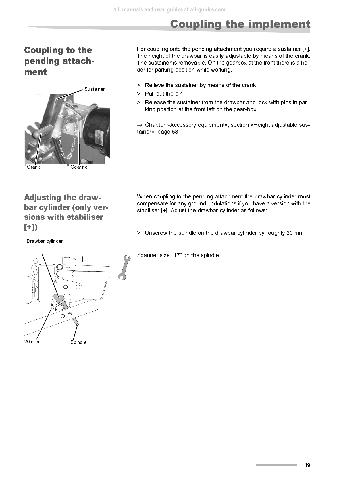
For coupling onto the pending attachment you require a sustainer [+].
The height of the drawbar is easily adjustable by means of the crank.
The sustainer is removable. On the gearbox at the front there is a hol-
der for parking position while working.
> Relieve the sustainer by means of the crank
> Pull out the pin
> Release the sustainer from the drawbar and lock with pins in par-
king position at the front left on the gear-box
→
Chapter »Accessory equipment«, section »Height adjustable sus-
tainer«, page 58
Adjusting the draw-
bar cylinder (only ver-
sions with stabiliser
[+])
When coupling to the pending attachment the drawbar cylinder must
compensate for any ground undulations if you have a version with the
stabiliser [+]. Adjust the drawbar cylinder as follows:
> Unscrew the spindle on the drawbar cylinder by roughly 20 mm
Spanner size "17" on the spindle
Crank Gearing
Sustainer
Spindle
20 mm
Drawbar cylinder
All manuals and user guides at all-guides.com
20
Coupling the implement
Coupling the car-
dan shaft
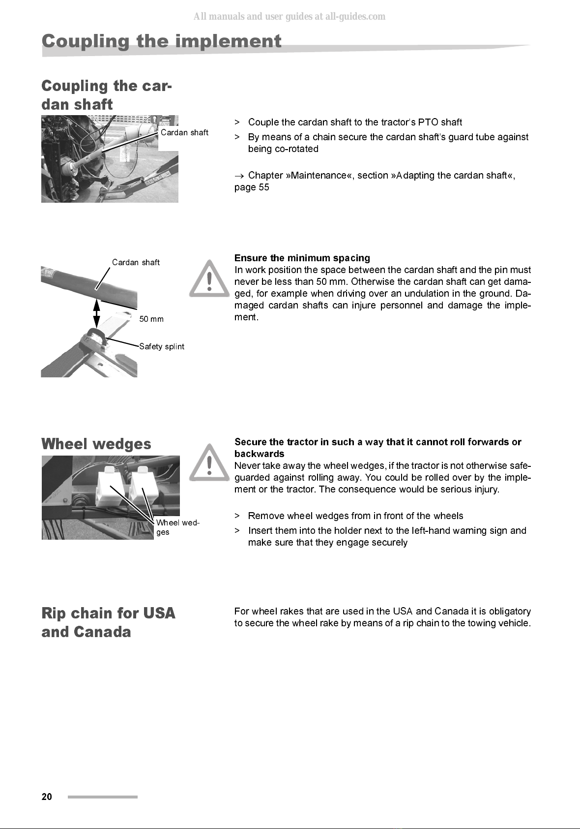
> Couple the cardan shaft to the tractor's PTO shaft
> By means of a chain secure the cardan shaft's guard tube against
being co-rotated
→
Chapter »Maintenance«, section »Adapting the cardan shaft«,
page 55
Ensure the minimum spacing
In work position the space between the cardan shaft and the pin must
never be less than 50 mm. Otherwise the cardan shaft can get dama-
ged, for example when driving over an undulation in the ground. Da-
maged cardan shafts can injure personnel and damage the imple-
ment.
Wheel wedges
Secure the tractor in such a way that it cannot roll forwards or
backwards
Never take away the wheel wedges, if the tractor is not otherwise safe-
guarded against rolling away. You could be rolled over by the imple-
ment or the tractor. The consequence would be serious injury.
> Remove wheel wedges from in front of the wheels
> Insert them into the holder next to the left-hand warning sign and
make sure that they engage securely
Rip chain for USA
and Canada
For wheel rakes that are used in the USA and Canada it is obligatory
to secure the wheel rake by means of a rip chain to the towing vehicle.
Cardan shaft
50 mm
Cardan shaft
Safety splint
Wheel wed-
ges
All manuals and user guides at all-guides.com
Other manuals for SwatMaster 7131 EVO
1
Other DEUTZ-FAHR Farm Equipment manuals


Popular Farm Equipment manuals by other brands

New Leader
New Leader NL450 Assembly/operators/parts manual

Raven
Raven AutoBoom XRT installation manual

Opico
Opico Air 8 Electronic operating instructions

TKS
TKS 3742 Operator's manual

Kverneland
Kverneland 608 Operator's manual

greenhouse sensation
greenhouse sensation Hydropod Assembly and maintenance instructions


