SB-2-001-F Page 5
Figure 10 Horizontal Test Pattern with Even Mate-
rial Distribution
If the pattern produced by the above test appears
normal,rotatetheaircapbacktoanormalspraying
position and begin spraying (Example - a normal
pattern with a #9000 air cap will be about 9" long
whenthe gun is held 8"from the surface.) With the
fluid adjusting screw open to the first thread and
the air pressure set at approximately 30 psi, make
afewtestpasseswiththegunonsomecleanpaper.
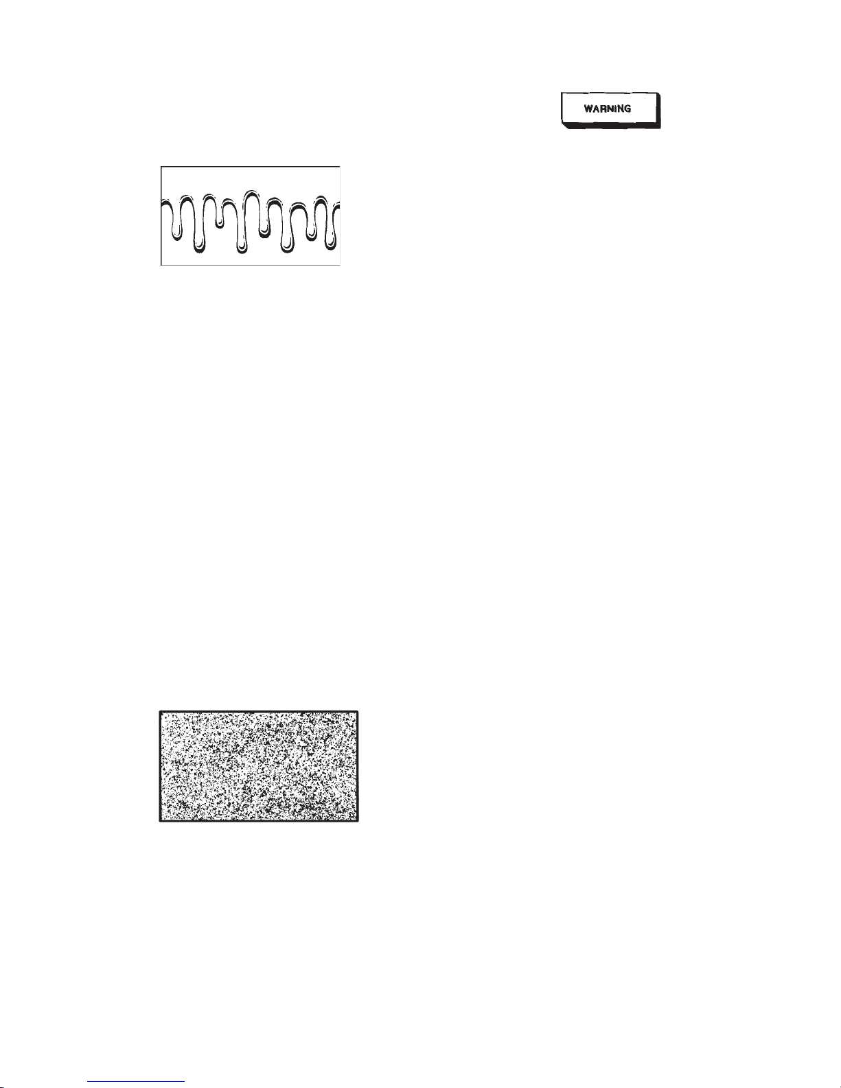
Move the gun faster than usual when spraying the
test passes. If there are variations in particle size -
specks and/or large globs, the paint is not atomiz-
ing properly (See Figure 12). If the paint is not
atomizingproperly,increasetheairpressureslightly
and make another test pass. Continue this se-
quence until the paint particle size is uniform.
If the pattern seems starved for material and the
fluid adjusting screw is open wide (to the first
thread), the atomization air pressure may be too
high,orthematerialmaybetooheavy.Recheckthe
viscosity or reduce the air pressure.
If the material is spraying too heavily and sagging,
reduce the material flow by turning in the fluid
adjusting screw (clockwise).
Figure 11 Pattern with Uneven Particle Size
Pressure Feed Components
Apressurefeed system consists of a pressurefeed
spray gun, pressure feed tank, cup or pump, an air
filter/regulator,appropriate airandfluid hosesand
anaircompressor.
Connecttheairhosefromtheairregulatortotheair
inlet on the gun. Connect the mainline air hose to
the air inlet on the tank, cup or pump.
To avoid hazardous bursting or equipment
damage, do not exceed the container's maxi-
mum working pressure.
Connect the fluid hose from the fluid outlet on the
tank or pump to the fluid inlet on the gun.
Openspreaderadjustmentvalveformaximumpat-
ternsize. Openfluidadjustmentscrewuntilthefirst
threadis visible.
Shut off atomization air to the gun. Set the fluid
flow rate by adjusting the air pressure in the mate-
rialcontainer.Useabout6psiforaremotecupand
about 15 psi for a 2-gallon, or larger, container.
Adjust the fluid flow in the following ways:
Remove the air cap. With atomization air off, pull
thetrigger,flowingmaterialintoaclean,graduated
container for 10 seconds. Measure the amount of
material which flowed in that time and multiply
times6(orflowfor30secondsandmultiplytime2).
This is the fluid flow rate in ounces per minute. For
standard finishing, it should be about 14 to 16
ounces per minute. If the flow rate is less than this,
increase the air pressure in the container and re-
peat.
When the flow rate is correct, reinstall the air cap.
Iffluidpressureatthetank,cuporpumpexceeds20
psi, the next larger fluid tip size should be used.
Turn the atomizaton air to about 30 psi at the gun.
Spray a fast test pattern on a clean sheet of paper
and check the consistency of the particle size.
Increase or decrease the air pressure until even
particle size is achieved.
Spray a horizontal test pattern holding the trigger
openuntilthematerialbeginstorun. Paintdistribu-
tionacrossthefullwidthofthepatternshouldbethe
same (adjust with fan pattern adjustment). If it
cannot be adjusted, there may be a problem with
either the air cap or the fluid tip which must be
corrected. Refer to the Troubleshooting Section.
Hints for good spray technique.
Hold gun perpendicular 6" to 8" (HVLP guns) or 8"-
10" (suction, gravity or pressure conventional feed
guns) to surface being sprayed.
Don'ttiltthe gun in anydirection.Thiswillresult in
unevenpaint build causing runs and sags.
Triggergunjustbeforetheedgeofthesurfacetobe
sprayed.Thetriggershouldbeheldfullydepressed
andthegunmovedinonecontinuousmotion,until
theotheredgeof theobjectisreached.Releasethe
triggerbutcontinuethemotionforafewinchesuntil
it is reversed for the return stroke.
If distribution is not even, there is a problem with
either the air cap or the fluid tip. Refer to the
TROUBLESHOOTINGsectionforexamplesoffaulty
patterns to help diagnose the problem.