3User's Manual | CMS631-Q470E/H420E
Table of Contents
Chapter 1 - Introduction................................................................................................................6
Specifications ......................................................................................................................... 6
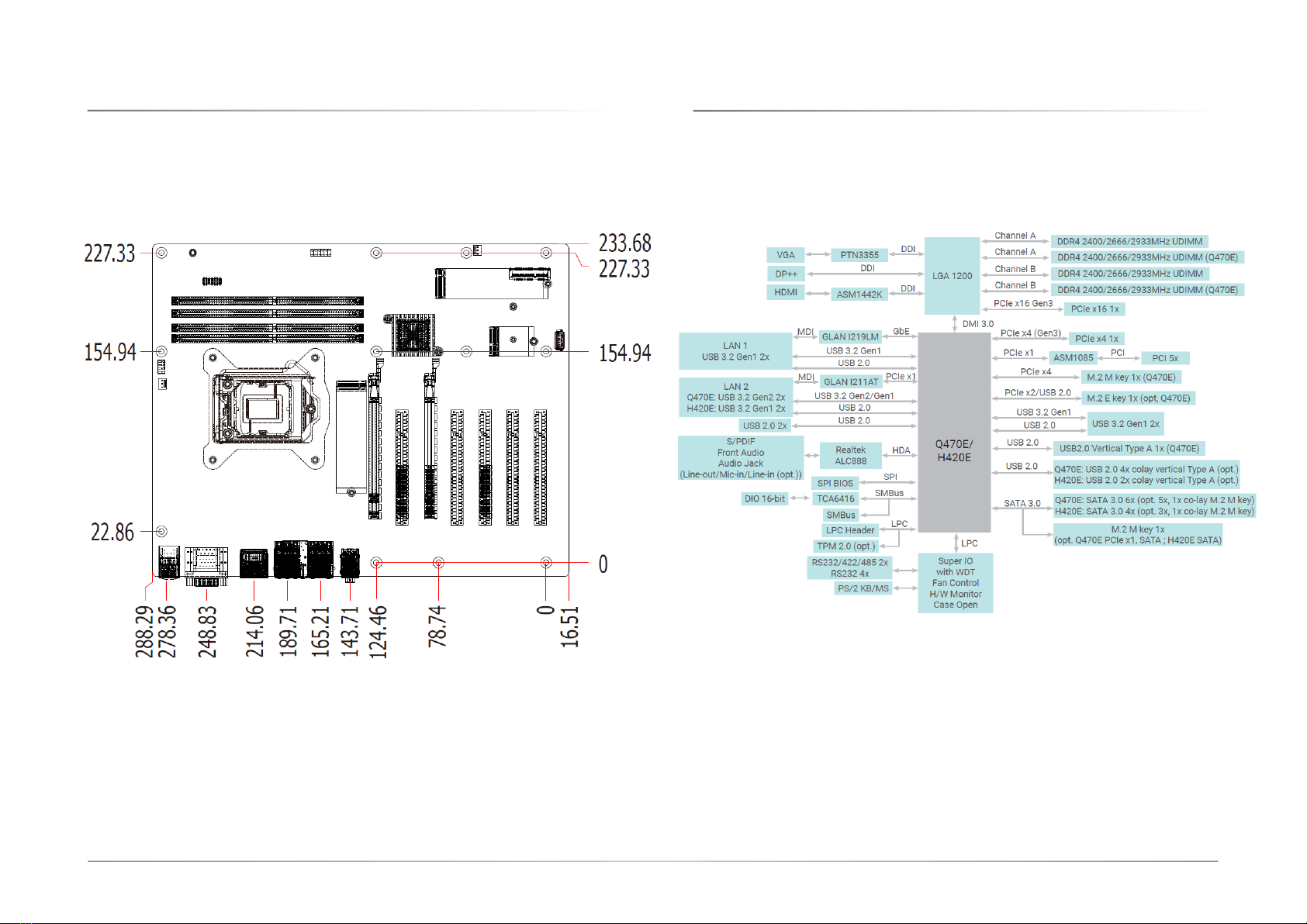
Dimensions ............................................................................................................................. 8
Block Diagram ........................................................................................................................ 8
Chapter 2 - Hardware Installation................................................................................................9
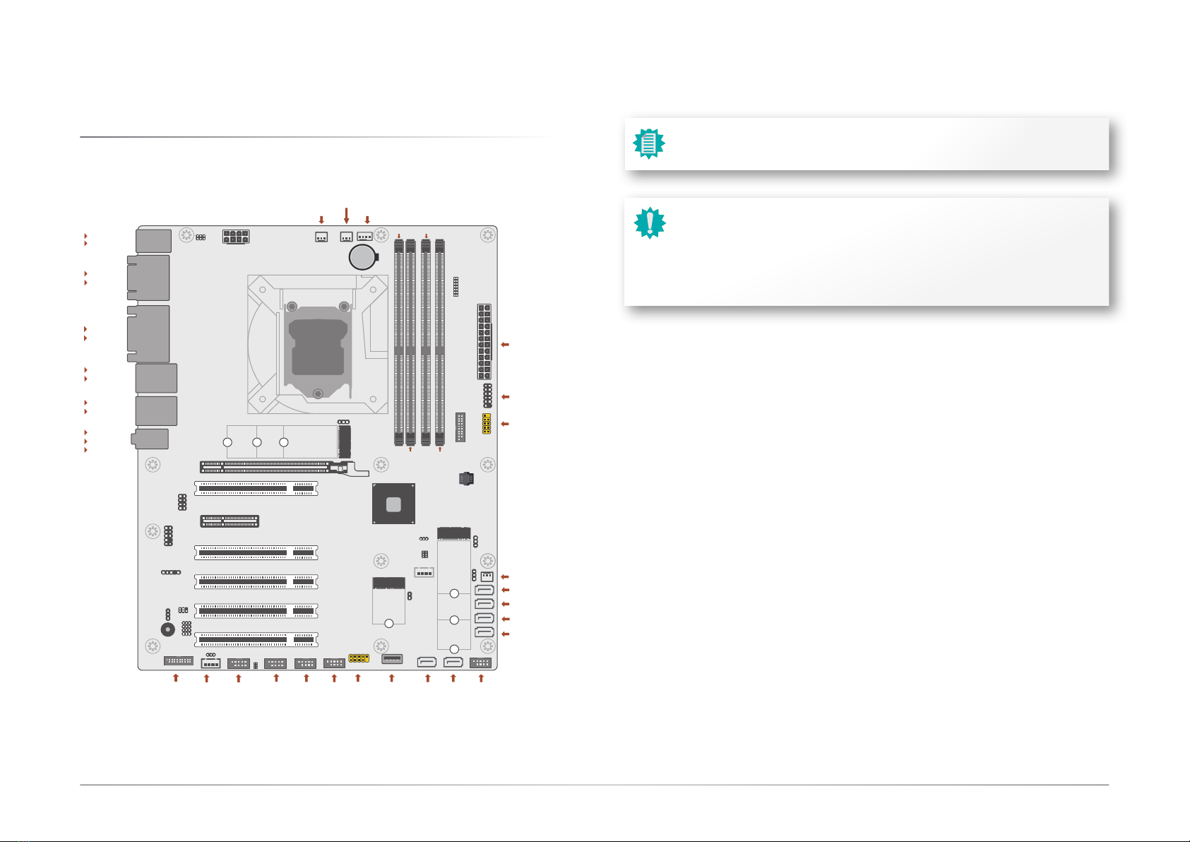
Board Layout........................................................................................................................... 9
System Memory ...................................................................................................................10
Installing the DIMM Module .........................................................................................10
Removing the DIMM Module........................................................................................11
CPU........................................................................................................................................12
Installing the CPU Fan and Heat Sink..........................................................................12
Jumper Settings ...................................................................................................................13
Clear CMOS Data (JP5) ................................................................................................13
COM1/COM2 RS232 Power Select (JP4&JP7)...........................................................13
DIO Power & Voltage (JP11/12/13/14/15) .................................................................14
AT/ATX Mode (JP26) ....................................................................................................14
M.2 Connector Power Control (JP27&JP28) ..............................................................15
Pin Assignment ....................................................................................................................15
InnoAGE HDR1 (JP24) ..................................................................................................15
USB Ports .......................................................................................................................16
Graphics Interfaces .......................................................................................................17
COM1..............................................................................................................................17
RJ45 LAN Ports .............................................................................................................18
Audio .............................................................................................................................18
Internal I/O Connectors .......................................................................................................19
SATA -Serial ATA (J31, J32, J17, J23, J24, J25) ........................................................19
Digital I/O Connector (J2).............................................................................................19
COM Ports (J9, J11, J13, J15, J16).............................................................................20
Cooling Fan Connectors................................................................................................21
Power Connector ...........................................................................................................21
Front Panel (J18)...........................................................................................................22
S/PDIF Connector (AUJ1).............................................................................................22
LPC Connector (J21).....................................................................................................23
Innoage HDD Power (CN37).........................................................................................23
Expansion Slots .............................................................................................................24
Expansion Slots....................................................................................................................24
Installing the M.2 Module .............................................................................................24
Battery ............................................................................................................................25
Chapter 4 - BIOS Settings...........................................................................................................26
Overview ...............................................................................................................................26
Main.......................................................................................................................................27
Advanced .............................................................................................................................27
RC ACPI Configuration..................................................................................................28
CPU Configuration.........................................................................................................28
Power & Performance ...................................................................................................29
PCH-FW Configuration ..................................................................................................29
Trusted Computing........................................................................................................30
NCT6126D Super IO Configuration ..............................................................................30
NCT6126D Super IO Configuration ►Serial Port 1,2 Configuration ...................31
NCT6126D Super IO Configuration ►Serial Port 3,4 Configuration ...................31
NCT6126D Super IO Configuration ►Serial Port 5,6 Configuration ...................32
NCT6126D HW Monitor ................................................................................................32
NCT5525D HW Monitor ►Smart FAN Function .................................................33
Serial Port Console Redirection ...................................................................................33
Serial Port Console Redirection ►Console Redirection Settings........................34
USB Configuration .........................................................................................................34
Network Stack Configuration........................................................................................35
CSM Configuration ........................................................................................................35
USB Power Control........................................................................................................36
Chipset ..................................................................................................................................37
Graphics Configuration .................................................................................................37
PEG Port Configuration.................................................................................................38
PEG Port Configuration ►PEG Port Feature Configuration................................38
PCH-IO Configuration ....................................................................................................39
PCH-IO Configuration ►PCI Express Configuration...........................................40
PCH-IO Configuration ►SATA And RST Configuration.......................................40
PCH-IO Configuration ► HD Audio Configuration..............................................41
Security .................................................................................................................................42
Secure Boot....................................................................................................................42
Boot .......................................................................................................................................43
Save & Exit ............................................................................................................................43
Updating the BIOS................................................................................................................44
Notice: BIOS SPI ROM..........................................................................................................44